Gira 5405 00 User manual

System 3000
Electronic switching insert
Electronic switching insert
Order no.: 5405 00
Operating instructions
1 Safety instructions
Electrical devices may only be mounted and connected by electrically skilled persons.
Serious injuries, fire or property damage possible. Please read and follow manual fully.
Danger of electric shock. Always disconnect before carrying out work on the devise or load.
Danger of electric shock. Device is not suitable for disconnection from supply voltage. The load
is not electrically isolated from the mains even when the device is switched off.
Risk of destruction if the set operating mode and load type do not match. Set correct operating
mode when connecting or exchanging the load.
Fire hazard. For operation with inductive transformers, each transformer must be fused on the
primary side in accordance with the manufacturer's instructions. Only safety transformers ac-
cording to EN 61558-2-6 may be used.
These instructions are an integral part of the product, and must remain with the end customer.
2 Intended use
– Operation with suitable cover
– Mounting in appliance box according to DIN 49073
Operation with neutral conductor
– Switching of incandescent lamps, HV halogen lamps, electronic or inductive transformers
with halogen or LED lamps, switchable or dimmable HV-LED or compact fluorescent
lamps, electrothermal actuators in combination with room temperature controller covers
Operation without neutral conductor
– Switching of incandescent lamps, HV halogen lamps, electronic or inductive transformers
with halogen or LED lamps, dimmable HV-LED or compact fluorescent lamps
Product characteristics
– Switch-on via bulb-preserving soft start
– Connection of extensions possible
– Electronic short-circuit protection with permanent switch-off after 7 seconds at the latest
– Electronic over-temperature protection
Flickering of the connected lamps through centralised pulses from the power stations.
This does not represent any defect in the device.
Operation with neutral conductor
– Device is powered via phase conductor and neutral conductor , therefore there is no lead-
ing edge phase control or trailing edge phase control.
Operation without neutral conductor
– Device is powered via the phase conductor and the connected load and therefore works
in the leading edge phase control or trailing edge phase control principle
– Automatic or manual setting of the suitable operating mode for the load
– Display of the set operating mode by means LED
Brief flickering upon load detection possible. No operation is possible during load detec-
tion.
1 / 7
82400512 24.05.2019

System 3000
Electronic switching insert
3 Operation
These instructions describe operation with a button cover. Operation with different covers is de-
scribed in the instructions for the cover in question. Operation using 2-wire extension with but-
ton cover or push-button corresponds to operation on the main device.
Switch load
■ Press the button cover: The load is switched on or off.
3-wire extension: Press top to switch on, press bottom to switch off.
4 Information for electrically skilled persons
4.1 Fitting and electrical connection
DANGER!
Mortal danger of electric shock.
Disconnect the device. Cover up live parts.
Figure1: Connection diagram with optional extensions
(1) Button Test
(2) Display LED and connection socket for cover
(3) 2-wire extension
(4) 3-wire extension
2 / 7
82400512 24.05.2019
System 3000
Electronic switching insert
(5) Push-button, NO contact
Connect 600 W LED lamps or compact fluorescent lamps at most per 16 A circuit
breaker. When connecting transformers, observe the data of the transformer manufac-
turer.
The connected load on LED lamps is dependent on the type of lamp and installation con-
ditions. The connected load of the specified values could vary. We cannot assume any
guarantee for proper function.
Operation with neutral conductor
When switched-off, switchable LED lamps can be dimly lit or flash repeatedly. Use dimmable
LED lamps.
Operation without neutral conductor
Compared with operation with neutral conductor, the maximum brightness can be reduced de-
pending on the type of lamp.
There could be an increased likelihood of unsuitable combinations of LED lamp and switch in-
sert.
Lit push-buttons must have a separate N terminal.
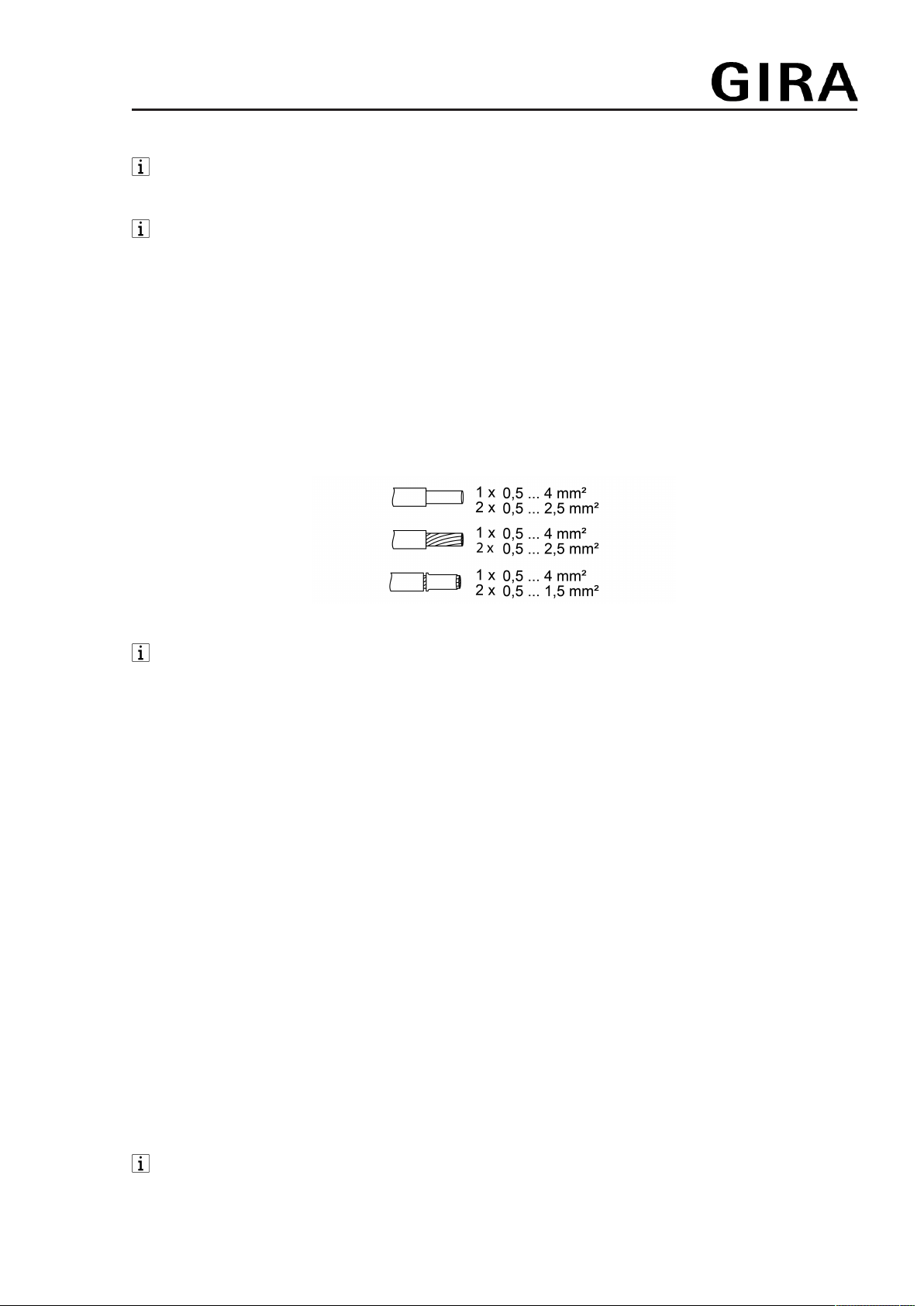
Figure2: Clampable conductor cross-section
The load can be switched by briefly pressing the Test button.
Reset the overheating protection / short-circuit protection
If the electronic overheating or short-circuit protection has been activated, separate the switch
insert from the grid for a few minutes.
4.2 Commissioning
Operation with neutral conductor
The device is powered via the phase conductor and neutral conductor. There is no leading edge
phase control or trailing edge phase control. Setting an operation mode is not necessary. There-
fore, button Test (1) and LED (2) have no function for commissioning.
Operation without neutral conductor
For operation without neutral conductor, the device is powered via the phase conductor and the
connected load. Therefore, the device operates in leading edge phase control or trailing edge
phase control. Generally, the device automatically sets the suitable operation mode. It may,
however, be necessary to set the operation mode manually.
Universal, R,L,C,LED
– Preset at the factory.
Automatic calibration to the load, dimming principle, trailing edge phase control, leading
edge phase control or LED leading edge phase control.
– Incandescent lamps, HV halogen lamps, dimmable HV-LED or compact fluorescent
lamps, dimmable electronic or inductive transformers for halogen or LED lamps.
LED trailing edge phase control, {
The connection of inductive transformers is not permitted.
3 / 7
82400512 24.05.2019
System 3000
Electronic switching insert
– Incandescent lamps, HV halogen lamps, electronic transformers for halogen or LED
lamps that can be dimmed according to the trailing edge phase control principle, HV-LED
or compact fluorescent lamps that can be dimmed according to the trailing edge phase
control principle.
LED leading edge phase control, |
The connection of inductive transformers is not permitted.
– Incandescent lamps, HV halogen lamps, electronic transformers for halogen or LED
lamps that can be dimmed according to the leading edge phase control principle, HV-LED
or compact fluorescent lamps that can be dimmed according to the leading edge phase
control principle.
Presetting the operating mode
Precondition: Load is switched off.
■ Press button Test (1) for longer than 4 seconds, until LED (2) lights up.
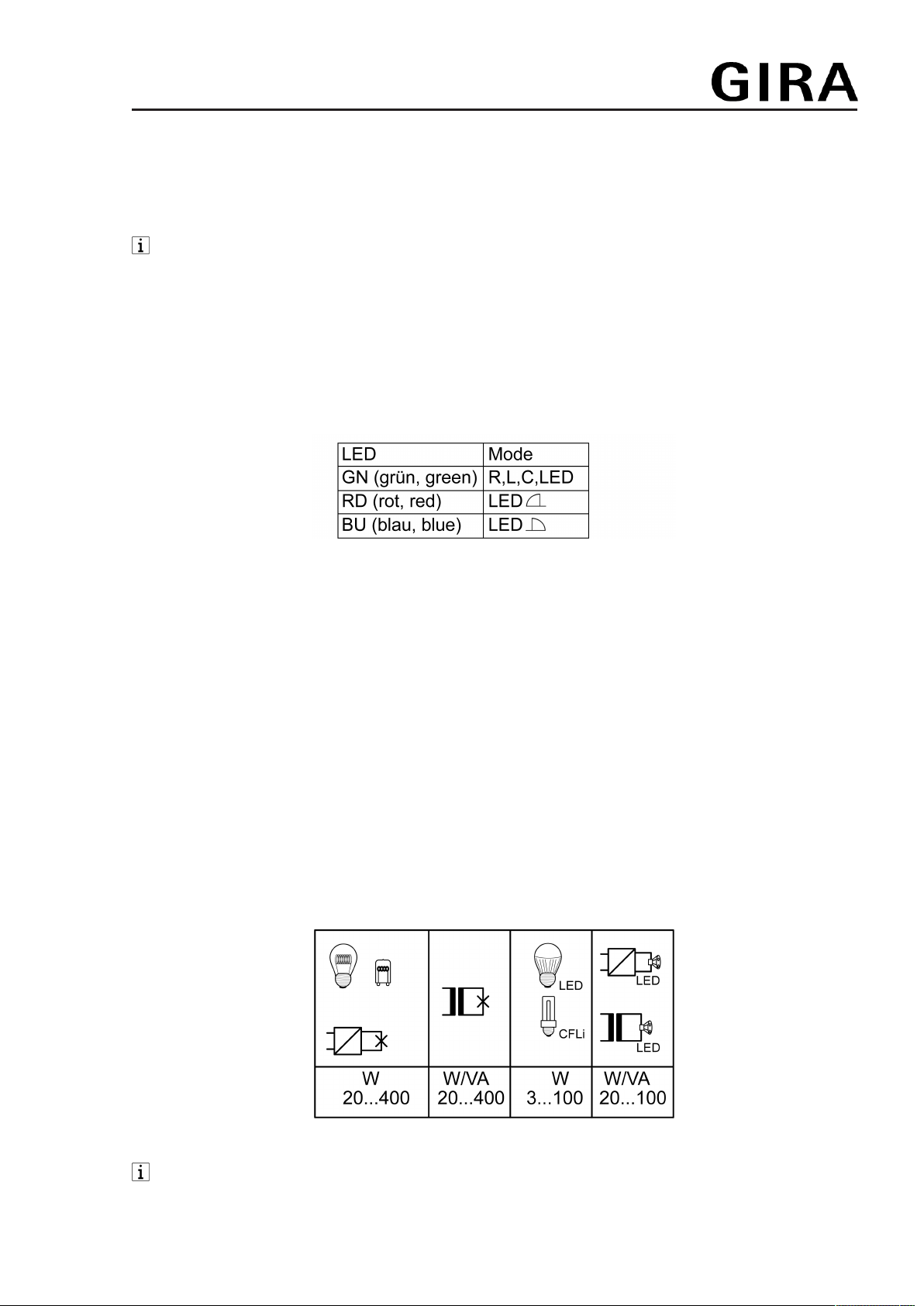
Figure3: Assignment of LED colour for the operating mode
■ Keep pressing button Test (1) for less than 1 second, until the necessary operating mode
is selected.
The LED (2) lights up in the colour of the selected operating mode (Figure 3).
■ Save the settings: Press the button Test (1) for more than 1 second or do not press for
30 seconds.
LED (2) goes out and the light is switched on: The operating mode is saved.
5 Technical data
Rated voltage AC 230 V~
Mains frequency 50 / 60 Hz
Standby load depending on the cover approx. 0.1 ... 0.5W
Power loss approx. 4 W
Ambient temperature -5 ... +45 °C
Connected load at 25°C (Figure 4)
Figure4: Connected load
When operating with neutral conductor or without neutral conductor in operating mode
{ : Connected load for HV-LED lamps typ. 3...200 W, electronic transformers with
NV-LED typ. 20...200 W.
4 / 7
82400512 24.05.2019

System 3000
Electronic switching insert
Mixed load
ohmic-capacitive 20 ... 400 W
capacitive-inductive not permitted
ohmic-inductive 20 ... 400 VA
Ohmic and HV LED typ. 3 ... 100 W
Ohmic and compact fl lamp. typ. 3 ... 100 W
Power specifications including transformer dissipation.
Operate inductive transformers with at least 85% nominal load.
Operation without neutral conductor in operating mode R,L,C,LED: Ohmic-inductive
mixed load: maximum 50% proportion of ohmic load. Otherwise, an incorrect measure-
ment is possible.
Operation without neutral conductor: Minimum load 50 W. Does not apply to loads with
HV-LED and compact fluorescent lamps.
Power reduction
per 5°C in excess of 25°C -10%
when installed in wooden or dry construction walls -15%
when installed in multiple combinations -20%
electrothermal actuators order no.: 2169 00
Number 1 ... 10
Number of extension units
2-wire, push-button unlimited
3-wire, rotary dimmer extension 10
Total line length
Extension max. 100 m
pwr cable max. 100 m
6 Troubleshooting
Connected lamps flicker
Cause: the specified minimum load is below the set level.
Increase the connected load.
Connected LED lamps or compact fluorescent lamps flicker or buzz, device buzzes
Cause 1: lamps are not dimmable and device is connected without neutral conductor
Connect neutral conductor if possible, otherwise exchange lamps for dimmable lamps.
Cause 2: operating mode and lamps do not optimally match.
Check operation in another operating mode, reduce connected load as well if necessary.
Set the operating mode manually.
Exchange lamps for another type.
The device switches the load off briefly and then on again.
Cause: short-circuit protection has tripped but now there is no longer a fault.
The device has switched off and cannot be switched on again.
Cause 1: overheating protection has tripped.
Disconnect device from mains by switching off circuit breaker.
LED trailing edge phase control: Reduce the connected load. Exchange lamps for another
type.
5 / 7
82400512 24.05.2019

System 3000
Electronic switching insert
LED leading edge phase control: Reduce the connected load. Check operation in the LED
trailing edge phase control setting. Exchange lamps for another type.
Let device cool down for at least 15 minutes.
Switch circuit breakers and device on again.
Cause 2: Surge protection has triggered.
LED trailing edge phase control: Check operation in the LED leading edge phase control
setting, reduce connected load as well if necessary.
Exchange lamps for another type.
Cause 3: short-circuit protection has tripped.
Disconnect device from mains by switching off circuit breaker.
Eliminate short-circuit.
Switch circuit breakers and device on again.
Short-circuit protection is not based on a conventional fuse, no metallic separation of the
operational current.
Cause 4: load failure.
Check load, replace light bulb. For inductive transformers, check primary fuse.
LED lamp is dimly lit when device is switched off
Cause: LED lamp is not suitable for this device.
Use a compensation module, see accessories.
Use another type of LED lamp or an LED lamp of another manufacturer.
Device has no function
Device is operated with a room temperature controller cover and electrothermal actuator and
the neutral conductor is not connected.
Connect a neutral conductor.
7 Accessories
Compensation module LED Order no. 2375 00
8 Warranty
The warranty is provided in accordance with statutory requirements via the specialist trade.
Please submit or send faulty devices postage paid together with an error description to your re-
sponsible salesperson (specialist trade/installation company/electrical specialist trade). They will
forward the devices to the Gira Service Center.
6 / 7
82400512 24.05.2019

System 3000
Electronic switching insert
Gira
Giersiepen GmbH & Co. KG
Elektro-Installations-
Systeme
Industriegebiet Mermbach
Dahlienstraße
42477 Radevormwald
Postfach 12 20
42461 Radevormwald
Deutschland
Tel +49(0)21 95 - 602-0
Fax +49(0)21 95 - 602-191
www.gira.de
7 / 7
82400512 24.05.2019
Table of contents
Other Gira Switch manuals


Popular Switch manuals by other brands


StarTech.com
StarTech.com ST7202USB Specifications

Kohler
Kohler KCT MPAC 1000 Operation and installation

LevelOne
LevelOne Infinity IES-1082 Quick installation guide

Grasslin
Grasslin Plug in Digital Time Switch instruction manual

Planet
Planet GS-5220 Series user manual

Ruijie
Ruijie RG-S7808C Series Hardware installation and reference guide


