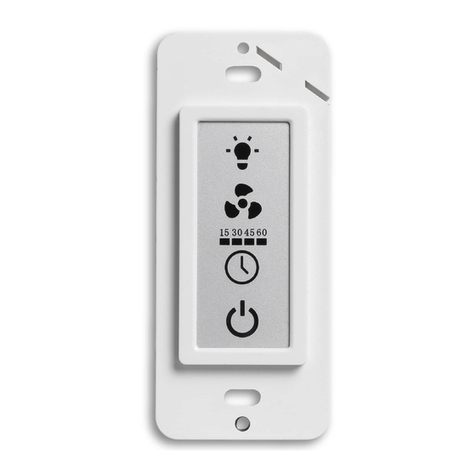
Gira System 2000 User manual

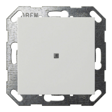
System 2000 automatic control switch 360° pure white
Order-No. : 2270 02
System 2000 automatic control switch 360° colour aluminium
Order-No. : 2270 04
Operating instructions
1 Safety instructions
Electrical equipment may only be installed and fitted by electrically skilled persons.
Failure to observe the instructions may cause damage to the device and result in fire and
other hazards.
Danger of electric shock. Always disconnect before carrying out work on the devise or
load. At the same time, take into account all circuit breakers that supply dangerous
voltage to the device or load.
Danger of electric shock. Device is not suitable for disconnection from supply voltage.
The load is not electrically isolated from the mains even when the device is switched off.
Do not press on the sensor window. Device can be damaged.
The device is not suitable for use as a burglar alarm or other alarm.
These instructions are an integral part of the product, and must remain with the end
customer.
2 Device components
Figure 1
(1) Flush-mounted insert
(2) Motion detector cover
(3) Adjuster sens
(4) Adjuster time
(5) Adjuster lux
(6) Brightness sensor
(7) LED display, behind the lens
(8) Lens
(9) Decor ring
(10) Push-on cover
1/8
82563812 18.11.2011
System 2000 automatic control switch 360°
System 2000

3 Function
Intended use
- Automatic switching of lighting depending on the heat motion and ambient brightness.
- Operation with concealed insert for dimming, switching or extension insert, 3-wire
- Ceiling installation on flush-mounted insert
Product characteristics
- Run-on time, sensitivity and brightness threshold settable
- Test operation for checking the detection area
- Short-time operation to control signal encoders
- Dimming phase in combination with dimming insert
- Saving a switch-on brightness with dimming inserts
- Dimming lights with dimming inserts
- Manual switch-on possible via extension insert, 2-wire, or installation button
- 78 lens segments in 5 recording levels
- Extension of the detection area in combination with the 3-wire extension insert
- Detection area can be limited using push-on cover
Automatic operation
The controller detects heat motions of people, animals and objects.
- The light is switched on if a person enters the monitored detection area and the brightness
is below the set threshold.
- The light is switched off if no more movement is detected in the detection area and the
follow-up time has elapsed.
Dimming phase with dimming insert
If the motion detector cover is fitted on a dimming insert, then when the run-on time elapses the
lighting is dimmed to minimum brightness and then switched off. The time from the start of
dimming to switching-off is always approx. 30 s. If a motion is detected during the dimming
phase, the motion detector switches the lighting to the stored switch-on brightness again.
Behaviour in case of a mains failure
- Less than 0.2 seconds: the old switching position is restored after mains return.
- 0.2 seconds to approx. 2 seconds: when the power returns, the lighting is switched on
again for the run-on time. Each detected movement restarts the run-on time again.
- Longer than 2 seconds: when the power returns, the motion detector carries out a brief
calibration process. Then the lighting remains switched on for the run-on time. Each
detected movement restarts the run-on time again.
LED display (7)
Main device Extension
LED lights up during the calibration process. LED lights up during the calibration process.
LED lights up when a motion is detected if the
lighting is switched off and the brightness is
not below the brightness threshold.
LED lights up when a motion is detected.
4 Operation
Switching on the light
A 2-wire extension or an installation button, NO contact is connected.
o Press extension or installation button.
Light is switched on independently of the brightness, with a dimming insert to switch-on
brightness. Automatic mode is active.
i After manual switch-on the run-on time is at least 2 minutes.
i Manual switch-on is not possible.
82563812 18.11.2011 2/8
System 2000
System 2000 automatic control switch 360°

Dimming light with dimming insert
The light can be dimmed using a 2-wire extension. The light remains at the dimmed value until
the run-on time has elapsed.
o Press 2-wire insert at top or bottom until the desired brightness is reached.
i An installation button cannot be used for dimming.
Saving a switch-on brightness with dimming insert
A 2-wire extension can be used to save any desired switch-on brightness. In the state as
supplied the switch-on brightness is set to maximum.
The saved switch-on brightness is retained in the event of a power failure.
o Set the required brightness.
o Press 2-wire extension for longer than 3 seconds over entire surface.
Switch-on brightness is saved. For confirmation the lighting switches off briefly and then on
again to the saved switch-on brightness.
5 Information for electrically skilled persons
5.1 Fitting and electrical connection
DANGER!
Electrical shock when live parts are touched.
Electrical shocks can be fatal.
Before carrying out work on the device or load, disengage all the
corresponding circuit breakers. Cover up live parts in the working environment.
Selecting the installation location
Figure 2: Sensor window and detection area
The motion detector has a detection area of 360° (Figure 2). The diameter of the detection area
depends on the installation height and the direction of motions of persons in the detection area
(Figure 3). At an installation height of 3 m the maximum diameter on the floor is approx. 12 to
20 m.
82563812 18.11.2011 3/8
System 2000
System 2000 automatic control switch 360°

Figure 3: Detection area dependent on the direction of movement
i Note direction of motion (Figure 3). Motions that are transverse to the motion detector
(Drawing B) can be detected better than motions towards or away from the motion detector
(Drawing A).
o Select a vibration-free installation location. Vibrations can lead to unwanted switching.
o Avoid interference sources in the detection area. Interference sources, e.g. heaters,
ventilation, air conditioners, and cooling light bulbs can lead to unwanted switching.
i If necessary, the detection area can be limited using the push-on top (see Limiting the
detection area).
i At an installation height of greater than 3 m the detection area increases, while at the same
time the detection sensitivity decreases.
Installing the motion detector cover
o Align the motion detector so that the brightness sensor is on the side away from the
windows. This reduces the effects of scattered light.
o Connect flush-mounted insert properly and mount in accordance with the orientation of the
motion detector (see instructions for flush-mounted insert).
i Use a surface-mounted housing for surface installation.
i Use a wind-tight connector socket for cavity wall mounting.
o Attach the motion detector cover to the flush-mounted insert.
Expanding the detection area
To expand the detection area, connect a 3-wire extension insert with motion detector cover. The
motion detector of the main unit also evaluates motion signals of the extension and, if
necessary, switches the lighting on.
o Connect extensions (see instructions for 3-wire extension insert).
i The sensitivity of motion detectors on extensions can be set individually. The brightness
threshold and run-on time are only set and evaluated on the main device.
i Do not connect any main units in parallel.
82563812 18.11.2011 4/8
System 2000
System 2000 automatic control switch 360°

5.2 Commissioning
Testing the detection area
Figure 4: Test setting
The motion detector is fitted and connected.
o Pull off push-on cover (10)
o Pull off decor ring (9).
o Set sens adjuster (3) to max(Figure 4).
o Set time adjuster (4) to test.
o Set lux adjuster (5) to 3 for brightness-independent switching.
o Switch on mains voltage.
The motion detector carries out a brief calibration process. The LED display behind the
lens lights up during the calibration process. After that test mode is active and the lighting
is switched on for approx. 1 second. As long as motions are detected, switch-on will take
place again after a lockout time of approx. 3 seconds.
In test operation the motion detector operates independently of the brightness.
o Leave the detection area and observe the switching behaviour.
If the motion detector switches on, then sources of interference must be hidden (see
Limiting the detection area).
o Measure the detection area.
If the detection area is too large, limit the detection area (see Limiting the detection area).
If the detection area is too small, expand the detection area using an extension.
o Make the operating settings for the run-on time, brightness threshold and sensitivity in
order to establish readiness for operation.
o Attach decor ring (9).
82563812 18.11.2011 5/8
System 2000
System 2000 automatic control switch 360°

Limiting the detection area
Figure 5: Push-on cover
The push-on cover can be used to limit the detection area, e.g. in order to mask out
interference sources.
Cover size Detection area on the floor
Complete push-on cover Ø approx 4.5 m
Area I cut out Ø approx 7.5 m
Areas I + II cut out Ø approx 12 m
without push-on cover Ø approx. 20m
All data are applicable for an installation height of 3 m and a direction of motion transverse to
the motion detector.
o Pull off push-on cover
o Using scissors, cut out push-on cover along the marked lines as required.
o Push on push-on cover
Set follow-up time
Then the lighting remains switched on for the length of the run-on time. Each detected
movement restarts the run-on time again. The run-on time is set in a range from
approx. 10 seconds to 30 minutes.
o Pull off decor ring.
o Turn the time adjuster (4) to the required position (Figure 4).
o Attach decor ring.
Setting test mode / short-time operation
The motion detector can be set to short-time mode, e.g. to use it to control acoustic signal
generators. If motion is detected, the motion detector switches on, depending on the brightness,
for 1 second. If motions are still detected, switch-on will take place again after a lockout time of
approx. 3 seconds.
o Pull off decor ring.
o Set time adjuster (4) to test(Figure 4).
o Turn sens adjuster (3) slightly in the min direction, because at maximum sensitivity
unwanted switching may occur.
82563812 18.11.2011 6/8
System 2000
System 2000 automatic control switch 360°

o Attach decor ring.
i To make the short-time operation independent of brightness, turn lux adjuster (5) to 3.
Setting the brightness threshold
Only when the brightness drops below the threshold will the light be switched on when there is
motion in the detection area. The brightness threshold is infinitely adjustable in a range from
approx. 0 to 80 lux and day operation . In so doing, the symbol stands for brightness-
independent switching and the symbol for switching in case of darkness.
o Pull off decor ring.
o Turn the lux adjuster (5) to the required position (Figure 4).
i Should the motion detector no longer react to detected movements in Night mode, 2
setting, turn the adjuster back somewhat towards 3.
o Attach decor ring.
Setting the sensitivity
The motion detector possess automatic adjustment to the ambient conditions. Normally, the
adjuster sens should be set to maximum sensitivity.
o Pull off decor ring.
o Set the sensitivity using the adjuster sens (3).
i If there are unwanted switching operations, reduce the sensitivity.
o Attach decor ring.
6 Appendix
6.1 Technical data
Ambient temperature +5 ... +35 °C
Protection rating IP 20
Brightness setting approx. 0 ... 80 lx (and day operation)
run-on time approx. 10 s ... 30 min
Lockout time approx. 2 s
Follow-up time (test) approx. 1 s
Lockout time (test) approx. 3 s
Size of detection area at an installation height of 3 m
cross walking range Ø approx. 20 m
walk to walking range Ø approx. 12 m
Detection angle 360 °
6.2 Troubleshooting
Light does not switch on, LED lights up upon detection
Cause: The ambient brightness is greater than the set brightness threshold.
Increase the brightness threshold using the lux adjuster (5).
Light does not switch on, LED does not light up
Cause 1: Detection area is limited by push-on cover.
Remove or adjust push-on cover.
Cause 2: Sensitivity is set too low.
Turn sens adjuster (3) in max direction.
Light switches on, although no-one is in the detection area.
Cause: Interference sources in the detection area, e.g. heating, ventilation, cooling light bulbs.
Reduce the detection area with push-on cover or reduce the sensitivity with the sens
adjuster (3).
82563812 18.11.2011 7/8
System 2000
System 2000 automatic control switch 360°

Light switches off briefly and then on again immediately, light oscillation
Cause 1: Interference sources in the detection area, e.g. heating, ventilation, cooling light bulbs.
Reduce the detection area with push-on cover or reduce the sensitivity with the sens
adjuster (3).
Cause 2: Installation error, main devices connected in parallel to expand the detection area.
Use extensions to expand the detection area.
6.3 Warranty
The warranty is provided in accordance with statutory requirements via the specialist trade.
Please submit or send faulty devices postage paid together with an error description to your
responsible salesperson (specialist trade/installation company/electrical specialist trade). They
will forward the devices to the Gira Service Center.
Gira
Giersiepen GmbH & Co. KG
Elektro-Installations-
Systeme
Industriegebiet Mermbach
Dahlienstraße
42477 Radevormwald
Postfach 12 20
42461 Radevormwald
Deutschland
Tel +49(0)21 95 - 602-0
Fax +49(0)21 95 - 602-191
www.gira.de
82563812 18.11.2011 8/8
System 2000
System 2000 automatic control switch 360°
This manual suits for next models
2
Table of contents
Other Gira Switch manuals
Popular Switch manuals by other brands

FlowLine
FlowLine LV42 Series Specifications-installation and operating instructions

Key Digital
Key Digital X4x1WUTx operating instructions

Force 10
Force 10 Traverse 2000 Hardware guide

Huawei
Huawei S9700 Series Configuration guide

Nortel
Nortel Nortel Power Branch Package 10 Release notes

Steren
Steren ALA-003 instruction manual