Lilin PS3188C User manual

i
PS3188C
16-Port Web Smart GbE PoE+ Switch
QUICK INSTALLATION GUIDE

ii
Contents
Chapter 1 Introduction .........................................................................1
Overview........................................................................... 1
Front View of the Switch ................................................. 1
Rear View of the Switch.................................................. 2
LED Descriptions ............................................................. 2
Mode/Reset Button.......................................................... 5
Chapter 2 Installing the Switch.........................................................6
Package Contents ........................................................... 6
Mounting the Switch in a 19-inch Rack......................... 6
Mounting the Switch on Desk or Shelf .......................... 7
Connecting the AC Power Cord ..................................... 7
Installing SFP Modules ................................................... 8
Chapter 3 Initial Configuration of Switch......................................9
Initial Switch Configuration Using Web Browsers........ 9
Initial Switch Configuration Procedure .......................... 9
Chapter 4 Troubleshooting ............................................................. 12

1
Chapter 1 Introduction
Overview
This user guide describes how to install, configure, and troubleshoot the
PS3188C, 16 RJ-45 + 2 Combo port Web Smart Switch, PoE 250W.
By reading this user guide, users can perform the following tasks:
•To check the switch status by reading the LED behavior
•To reset the switch or to restore the switch to factory defaults
•To install the switch on the rack, on the wall, or on the desk
•To use a Web browser to initially configure the switch
•To troubleshoot the switch
Front View of the Switch
Figure 1: Front panel of the switch

2
Rear View of the Switch
Figure 2: Rear panel of the switch
LED Descriptions
The LEDs on the front panel provide users with switch status checking and
monitoring. There are three types of LEDs as follows:
•System LED indicates if the switch is powered up correctly or not, or,
indicates if there is a system alarm triggered for troubleshooting.
•Mode LEDs indicates the mode of all RJ45/SFP ports on the switch.
Users can press the Mode button sequentially to switch among the two
different modes (Link/Activity/Speed mode and PoE mode).
•Port Status LEDs indicates the current status of each RJ45/SFP port.
Users can check these LEDs to understand the port status in different
modes, after changing the mode by pressing Mode button.
The following table details the functions and descriptions of various LED
indicators. Table 1: System LED
LED
Color
State
Description
System
Green
On
The switch is powered ON correctly.
Off
The switch is not receiving power.
Red
On
An abnormal state, such as exceeding
operating temperature range, has been
detected in the switch.

3
Table 2: Mode LEDs
LED
Color
State
Description
Link/Act/
Speed
Green
On
The RJ45/SFP Port Status LEDs are
displaying
link status and network activity of each
port, with connection speed of 1000Mbps.
Amber
On
The RJ45/SFP Port Status LEDs are
displaying
link status and network activity of each
port, with connection speed of
10/100Mbps.
PoE
Green
On
The RJ45 Port Status LEDs are
displaying
PoE powering status of each port.

4
Table 3: Port Status LEDs
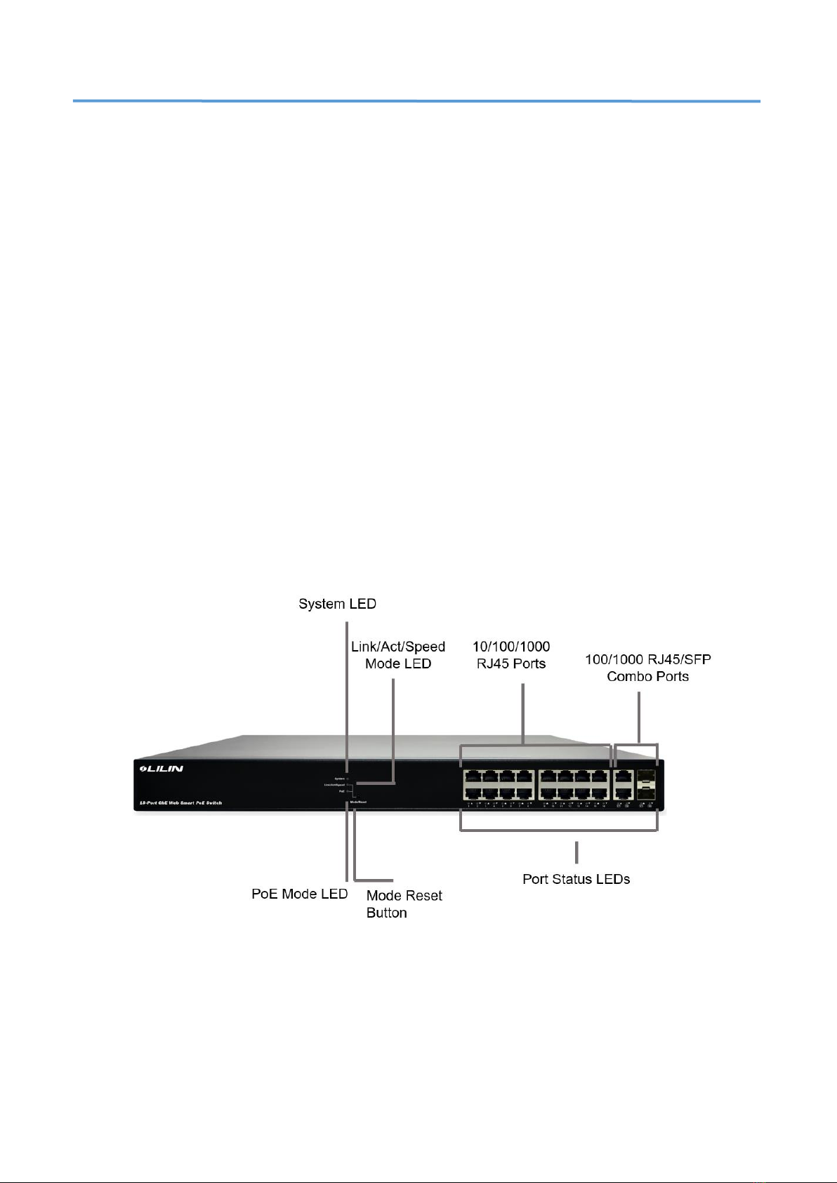
By pressing the MODE button in less than 2 seconds to change LED modes
(Link/Act/Speed Mode or PoE Mode), users can check the port status by reading
the LED behaviors per the table below.
When Link/Act/Speed Mode LED Lit
LED
Color
State
Description
RJ45
Ports
Green
On
The port is enabled and established a link to connected
device, and the connection speed is 1000Mbps.
Green
Blinking
The port is transmitting/receiving packets, and the
connection speed is 1000Mbps.
Ambe
r
On
The port is enabled and established a link to connected
device, and the connection speed is 10/100Mbps.
Ambe
r
Blinking
The port is transmitting/receiving packets, and the
connection speed is 10/100Mbps.
--
Off
The port has no active network cable connected, or it is not
established a link to connected device. Otherwise, the port
may have been disabled through the switch user interface.
SFP
Ports
Green
On
The port is enabled and established a link to connected
device, and the connection speed is 1000Mbps.
Green
Blinking
The port is transmitting/receiving packets, and the
connection speed is 1000Mbps.
Ambe
r
On
The port is enabled and established a link to connected
device, and the connection speed is 100Mbps.
Ambe
r
Blinking
The port is transmitting/receiving packets, and the
connection speed is 100Mbps.
--
Off
The port has no active network cable connected, or it is not
established a link to connected device. Otherwise, the port
may have been disabled through the switch user interface.
When PoE Mode LED Lit
LED
Color
State
Description
RJ45
Ports
Green
On
The port is enabled and supplying power to connected
device.
Ambe
r
On
An abnormal state, such as overload status, has been
detected in the switch.
--
Off
The port has no active network cable connected, or it is not
connected a PoE PD device. Otherwise, the port may have
been disabled through the switch user interface.

5
Mode/Reset Button
By pressing the Mode/Reset Button for certain period of time, users can
perform the following tasks.
•Change Port Status LED Mode to read the port status correctly in the
two different modes (Link/Act/Speed mode or PoE mode).
•Reset the Switch to reboot and get the switch back to the previous
configuration settings saved.
•Restore the Switch to Factory Defaults to restore the original
factory default settings back to the switch.
Note: According to the table below, users can easily judge which task is
being performed by reading the LED behaviors while pressing the
Mode/Reset button. Once the LED behaviors are correctly
displayed, users may just release the button.
Table 4: Mode/Reset Button Descriptions
Task to be
Performed
Time Period
of Pressing
Button
SYS LED
Behavior
Port Status LED
Behavior
Change LED
Mode
0 ~ 2 seconds
ON
Green
LED status will be changed
according the mode selected.
Reset the Switch
2 ~ 7 seconds
Blinking
Green
ALL LEDs
Light OFF
Restore to
Defaults
7 ~ 12
seconds
Blinking
Green
ALL LEDs
Stay ON

6
Chapter 2 Installing the Switch
Package Contents
•The Switch
•AC Power cord
•Four adhesive rubber feet
•Installation Guide
•Mounting kit
Note: The switch is an indoor device. If it is to be used with outdoor devices
such as outdoor IP cameras or outdoor WiFi APs, then users are
strongly suggested to install a surge protector or surge suppressor in
order to protect the switch.
Mounting the Switch in a 19-inch Rack
Step 1: Attach the mounting brackets to both sides of the chassis. Insert screws
and tighten then with a screwdriver to secure the brackets.
Figure 3: Attaching Brackets to the Switch
Step 2: Place the switch on a rack shelf in the rack. Push it in until the oval holes
in the brackets align with the mounting holes in the rack posts.
Step 3: Attach the brackets to the posts. Insert screws and tighten them.
Figure 4: Attaching Brackets to the Rack Post

7
Mounting the Switch on Desk or Shelf
Step 1: Verify that the workbench is sturdy and reliably grounded.
Step 2: Attach the four adhesive rubber feet to the bottom of the switch.
Figure 5: Attaching the Rubber Feet
Connecting the AC Power Cord
Step 1: Connect the AC power cord to the AC power receptacle of switch.
Step 2: Connect the other end of the AC power cord to the AC power outlet.
Step 3: Check the SYS LED. If it is ON, the power connection is correct.
Figure 6: Connecting AC power cord

8
Installing SFP Modules
You can install or remove a mini-GBIC SFP module from a SFP port without having
to power off the switch.
Step 1: Insert the module into the SFP port.
Step 2: Press firmly to ensure that the module seats into the connector.
Figure 7: Installing a SFP Module into a SFP Port

9
Chapter 3 Initial Configuration of
Switch
Initial Switch Configuration Using Web Browsers
After powering up the switch for the first time, you can perform the initial
switch configuration using a web browser. For managing other switch
features, please refer to the Web interface user guide for details.
To begin with the initial configuration stage, you need to reconfigure your
PC’s IP address and subnet mask so as to make sure the PC can
communicate with the switch. After changing PC’s IP address (for example,
192.168.0.250), then you can access the Web interface of the switch using
the switch’s default IP address as shown below.
Note: The factory default IP address of the switch is 192.168.0.1
The factory default Subnet Mask of switch is 255.255.255.0
Initial Switch Configuration Procedure
The initial switch configuration procedure is as follows:
1. Power up the PC that you will use for the initial configuration. Please
make sure the PC has the Ethernet RJ45 connector to be connected
to the switch via standard Ethernet LAN cable.
2. Reconfigure the PC’s IP address and Subnet Mask as below,
so that it can communicate with the switch. The method to change
the PC’s IP address, for example, for a PC running Windows®
7/8.x/10, is as follows:

10
Step 1:Type “network and sharing“ into the Search box in the Start
Menu
Step 2:Select Network and Sharing Center
Step 3:Click on Change adapter settings on the left of PC screen
Note:Users can also skip step 1 to 3, by pressing WinKey+Rand
type ”ncpa.cpl”command to get to step 4 directly.
Step 4:Right-click on your local adapter and select Properties
Step 5:In the Local Area Connection Properties window
highlight Internet Protocol Version 4 (TCP/IPv4) then click
the Properties button.
Note:Be sure to record all your PC’s current IP settings to be able to
restore them later.
Step 6:Select the radio button Use the following IP address and
enter in the IP for the PC (e.g. any IP address not in use, and
in between 192.168.1.2 and 192.168.1.254), Subnet mask
(e.g. 255.255.255.0), and Default gateway that corresponds
with your network setup. Then enter your Preferred and
Alternate DNS server addresses.
Step 7:Click OK to change the PC’s IP address.
3. Power up the switch to be initially configured, and wait until it has
finished its start-up processes.
4. Connect the PC to any port on the switch using a standard Ethernet
cable, and check the port LED on the switch to make sure the link
status of the PC’s is OK.
5. Run your Web browser on the PC, enter the factory default IP
address, so as to access the switch’s Web interface.
If your PC is configured correctly, you will see the login page of the
switch as shown by Figure 9 below.

11
Figure 9: Web Interface login page
If you do not see the above login page, please perform the following
steps:
- Refresh the web page.
- Check to see if there is an IP conflict issue.
- Clean browser cookies and temporary internet files.
- Check your PC settings again and repeat step 2.
6. Enter the factory default username and password in login page.
Click “Login” to log into the switch.
Note: The factory default Username of the switch is admin
The factory default Password of the switch is admin

12
Chapter 4 Troubleshooting
The following table provides information for users to easily troubleshoot problems by taking
actions based on the suggested solutions within.
Table 5: Troubleshooting Table
Symptoms
Possible Causes
Suggested Solutions
SYSTEM LED is
Off
The switch is not
receiving power.
1. Check if correct power cord is connected
firmly to the switch and to the AC outlet socket.
2. Perform power cycling the switch by
unplugging and plugging the power cord back
into the switch.
3. If the LED is still off, try to plug power cord
into different AC outlet socket to make sure
correct AC source is supplied.
SYSTEM LED is
RED
An abnormal
state has been
detected by the
switch.
Check the system log within the switch
from WEB UI to understand the abnormal
state (e.g. exceeding operating
temperature range) and take
corresponding actions to resolve.
Port Status LED
is Off in the
Link/Act/Speed
Mode
The port is not
connected or the
connection is not
working.
1. Check if the cable connector plug is firmly
inserted and locked into the port at both the
switch and the connected device.
2. Make sure the connected device is up and
running correctly.
3. If the symptom still exists, try different cable or
different port, in order to identify if it is related to
the cable or specific port.
4. Check if the port is disabled in the
configuration settings via WEB user interface .
Port Status LED
is Off in the
PoE Mode
The port is not
supplying power
1. Check if the cable connector plug is firmly
inserted and locked into the port at both the
switch and the connected device.
2. Make sure the correct Ethernet cables are
used.
3. If the symptom still exists, try different cable or
different port, in order to identify if it is related to
the cable or specific port.
4. Check if the port is disabled in the
configuration settings via WEB user interface .
Table of contents
Other Lilin Switch manuals

Lilin
Lilin pmh-poe570wat User manual

Lilin
Lilin PMH-POE0570W User manual

Lilin
Lilin PS3108C User manual

Lilin
Lilin PIH-308 User manual

Lilin
Lilin PMH-POE08130WT4 User manual

Lilin
Lilin PMH-POE08130WAT User manual

Lilin
Lilin PS3064DM User manual

Lilin
Lilin PMH-POE08260W User manual

Lilin
Lilin PS3268C User manual
Popular Switch manuals by other brands

ZyXEL Communications
ZyXEL Communications Dimension ES-4124 user guide

Nortel
Nortel Ethernet Routing Switch 8000Series Installing and maintaining

Extron electronics
Extron electronics SW6 AV MX AS user manual

Televes
Televes MULTRIX MS94NG manual

Brocade Communications Systems
Brocade Communications Systems VDX 6720 Hardware reference manual

HP
HP A5500 HI Series installation guide