© 2018 nVent
89112276 - 9 -
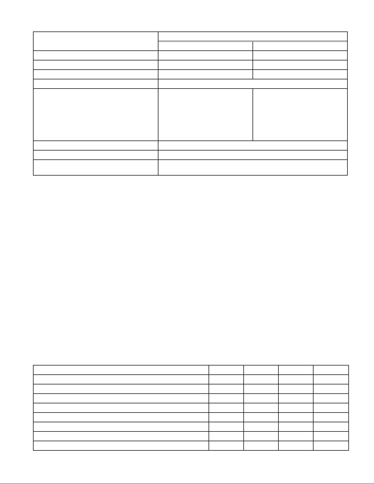
Table 2- Design Data Electronic Control
Technical Data Part Number
TEC24CNTLRN TEC48CNTLRN
Rated Voltage (VDC) 24 48
Operating Range (VDC) 18 to 30 40 to 60
Maximum Current @ Rated Voltage (Amps) 17.2 8.6
Operating Temperature (°F/°C) -40 to +149/ -40 to +65
Alarm Contact Rating
1) 0.5 A max @ 24 VDC - from
same source of power as unit,
SELV, non-power limited (greater
than 15 W);
OR
2) 0.5 A max @ 24 VAC - from
SELV, Class 2 safety isolating
transformer.
1) 0.5 A max @ 48 VDC - from
same source of power as unit,
SELV, non-power limited (greater
than 15 W);
OR
2) 0.5 A max @ 24 VAC - from
SELV, Class 2 safety isolating
transformer.
Temperature Accuracy (°F/°C) ±3.6/2
High Temperature Alarm (°F/°C) 27/15 above cooling setpoint
Low Temperature Alarm (°F/°C) * 18/10 below heating setpoint,
N/A if heating is disabled.
* If heating is disabled, there is no low temp alarm.
OPERATION OF ELECTRONIC CONTROL
Each time power is applied, the controller will step though a start-up sequence. This consists of indicating the
current cooling and heating settings, and turning on the cooling and heating function such that proper operation
of the TEC can be veried. The sequence is as follows:
1. The blue cooling LED blinks for a half second ON and half second OFF for the appropriate number
of times (see Table 1 - Cooling and Heating Setpoints).
2. The red heating LED blinks for half second ON and half second OFF for the appropriate number of
times (see Table 1 - Cooling and Heating Setpoints).
3. The TEC ramps up in cooling mode for 5 seconds. The blue cooling LED ashes rapidly.
4. The TEC ramps up in heating mode for 5 seconds. The red heating LED ashes rapidly.
The controller will command the TEC to cool if the temperature read by the thermistor is above the cooling
setpoint, and to heat if the temperature is below the heating setpoint. If heating is called for, the controller will
automatically reverse the DC voltage to the TE modules. During cooling, H+ is a higher potential than H-. During
heating, H- is a higher potential than H+. The controller logic will slowly ramp power to the peltier chips. If the
temperature read by the thermistor is between the cooling and heating setpoints, the controller will be in a
standby mode with no power applied to the TEC modules.
The normally open (NO) alarm dry contact will close when an alarm occurs, including loss of power. The normally
closed (NC) contact will open when an alarm occurs.
Table 3 - LED and alarm connection status
Status Red Blue Com-NO Com-NC
OFF OFF OFF Closed Open
Start up sequence - see Table 1 - Cooling and Heating Setpoints Flashes Flashes Toggles Toggles
ON – Standby OFF OFF Open Closed
ON – Cooling OFF ON Open Closed
ON – Cooling/High Temp Alarm Flashing ON Closed Open
ON – Heating ON OFF Open Closed
ON – Heating/Low Temp Alarm ON Flashing Closed Open
ON – Temp Sensor Failure Flashing Flashing Closed Open