GJD D-TECT 2 GJD300 User manual

-1-04111
D-Tect 2
GJD300 Quad PIR Movement Detector
Package Contents
Package Contains:
●1 x D-Tect 2
●1 x Drilling template for fixing holes
●1 x Allen Key
● x 1.75mm wall plugs
● x 1.75mm screws
●2 x Spare Sliding Curtains
●2 x Tamper Feet
●1 x Tamper Cup
●1 x Installation manual
Introduction
The D-Tect 2 is an outdoor motion detector and alarm
trigger that uses two independent passive infra-red
detectors, both of which must trigger to cause the detector
to signal an alarm. Utilising quad PIR technology, the D-Tect
2 delivers precise, reliable presence detection.
. Feed standard eight-core alarm cable into the
cable entry. Bare the wires and connect to the top
PCB terminal block. See Figures 2, 4 & 5.
4. Screw the unit to the wall ensuring that the rear
tamper pin is correctly located and that the tamper
microswitch is closed. See Figure 6.
To aid installation, two spare tamper feet are
provided. One is 1mm longer and the other is 2mm
longer than the tamper foot originally fitted. The
tamper foot is a push fit and can be removed by
carefully pulling it from the pin. See Figure 2.
5. When the detector is aligned, connected, and
programmed to suit the installation, replace the
front cover and lock as shown. See Figure 7.
The multifunction lens fitted to D-Tect 2 produces seven
long range beams and seven medium to short range curtain
PIR beams. The PIR circuitry detects changes in heat and
movement in the beam pattern; therefore items such as
trees, shrubs, ponds, boiler flues, and animals should be
considered when positioning the detector.
Note: The PIR sensor is more sensitive to movement
across the beams, and less sensitive to movement directly
towards or away from the beams.
The detector module is fitted with two sliding shutters to
reduce the detection angle.
The curtains are fitted to the pan and tilt module as shown
in Figure 9 (shown with primary and additional curtain
sliders fitted). Each section of the detector lens gives a
coverage pattern of approximately 10 degrees.
An additional set of curtain sliders is provided should the
beam pattern need to be narrowed even further, e.g. if the
minimum detection angle of 10 degrees is required.
When coverage exceeds the desired detection area, adjust
the module as required and mask off any beams, either
vertically or horizontally, to avoid unwanted detection.
Quick Installation
1. Mount and connect the detector following the
instructions given later in this sheet.
2. Apply supply voltage to the unit. The detection LED
(blue) flashes three times.
. Wait approximately 2 to minutes to allow the
detector to settle.
4. Press the programming button once to activate
walk test mode. The detection LED is now enabled
for five minutes.
Note: The front cover must be fitted when walk
testing.
The default settings are:
●Range: 20 meters
●Pulse count: 1 (always set to 1 during walk test)
●Detection LED: off (always enabled during Walk
Test)
●'S' Lux Level: 5
●Contacts:
●Alarm 1: Normally Closed
●Alarm 2: Normally Open
●Contacts Timer: 5 (seconds)
Mounting The Unit
Multibeam Alignment & Masking
During installation, protect the electronics against water, as
trapped moisture can affect or damage the unit.
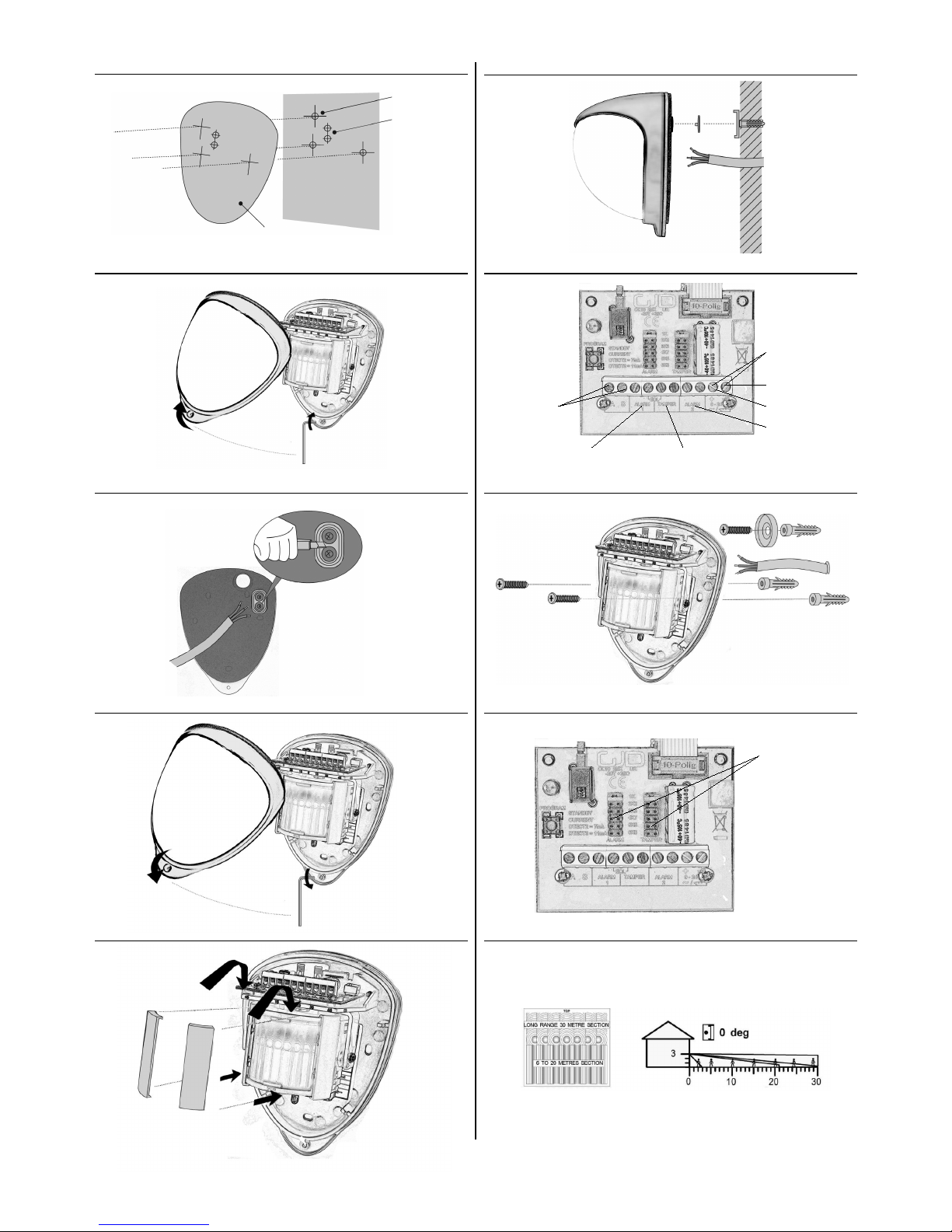
1. Drill the wall to accept the two fixing screws, the
cable entry, and the tamper cup (if used). See
Figures 1 and 2.
A hole-drilling template is provided.
Note: We recommend using the tamper cup on
uneven wall surfaces.
2. Remove the cover assembly by loosening the
locking screw using the allen key provided. The
cover hinges from the top and lifts out of the
location slot. See Figure .
The D-Tect 2 includes jumpers that allow you to configure
the internal end-of-line resistor values, when EOL resistors
are required. Values are 1K, 2K2, K , 4K7, 5K6 and 6K8
Ω. Figure 8 shows:
1. EOL resistor jumpers
2. Wiring points
Alternatively, you can remove the jumpers and connect a
discrete resistor directly to the alarm or tamper outputs, as
specified by the third-party equipment.
Connections
Connecting The Unit
Terminal Label Description
1A 24 hour -VE Output
2 S Dark -VE Output
, 4 ALARM 1 Alarm relay 1
4, 5 EOL End-of-line resistors
5, 6 TAMPER N/C Tamper relay, normally closed
7, 8 ALARM 2 Alarm relay 2
9, 10 9 -24V AC / DC Supply

--04111
Figure 12 shows the pattern for the maximum range in the
optimum position (see Figure 10). Masking the top section
of the lens reduces the range to 20m.
Figure 1 shows the pattern for the minimum range. In this
case masking the top section of the lens reduces the range
to 6 meters.
Figures 14 and 15 illustrates alignment recommendations
for when the detector is mounted close to a wall.
The alignment shown in Figure 14 is not recommended. If
the detector module is orientated at an angle of 90° to the
perimeter, the mounting wall may cut off short and medium
range beams. The long range beam will still detect an
intruder, however the wall can cause false alarms when
heated by sunlight.
Figure 15 shows the recommended alignment. The detector
module is orientated at a 55° angle to the perimeter. As a
result, short and medium range beams are parallel to the
perimeter, but the detection range along the perimeter is
reduced to 25 metres.
The user can individually program a number of configurable
settings, as illustrated in the programming chart.
Programming
SETTING
1 3 4 5 6 7 8
O
P
T
I
O
N
S
1 Range (m) 8 15 20 25 0
Pulse Count 1 2
3 LED Off On
4'S' Output
Lux Level 2 5 10 20 0 40 50 24
HR
5Contacts
Alarm 1 N/O N/C N/C
Alarm N/O N/O N/C
6 Timer Seconds 2 5 10 20 0 40 50 60
A
U
X
7Press 7 times to flash out your selected settings
8Press 8 times to reset to GJD factory settings
Shaded settings are factory defaults
To change any of the D-Tect 2 settings:
1. Press the program button, as shown in figure 16,
for the number of the Option to be changed, i.e.
once for range, twice for pulse count, three times
for LED, four times for lux, five times for contacts
and six times for timer.
Note: If using the IR Key Fob, press the key fob
button instead of the detector's program
button. See Figure 17.
2. Wait until the blue LED indicator goes off (typically
four seconds).
. The indicator will then flash out the existing
settings.
4. To change the settings for that option, press the
program button the number of times for the
required new setting.
5. The indicator blinks twice and the changes are
stored in the D-Tect 2's non volatile memory.
Note: When power is applied to the D-Tect , the user
has a time slot of 5 minutes to start using the IR key
fob. This can be reset either by pushing the program
button as shown in figure 16 or by removing then
reapplying power to the D-Tect .
Example: To change the LED setting from OFF to ON:
1. Press the program button three times.
Note: If using the IR Key Fob, press the key fob
button instead of the detector's program
button. See Figure 17.
2. Wait until the blue LED indicator goes off (typically
four seconds).
. The indicator will then flash once, indicating the
current LED setting is OFF.
4. Press the program button twice to change the
setting to ON.
5. The indicator blinks twice and the changes are
stored in the D-Tect 2's non volatile memory.
Programming O tions Definitions
Pulse Count
This is the number of times the unit has to detect on both of
its sensors before signalling an output.
LED
LED Off – LED disabled.
LED On – LED signals a detection.
Lux Level
This is the approximate level that the ambient light must
reach before the 'S' output will become active when there is
an activation.
The 'S' output switches negative for 60 seconds when there
is a detection and the light level is below the programmed
setting.
The 'S' output is an open collector type rated at maximum
25mA.
Alarm 1 & Alarm Outputs
These are magnetically immune volt free relay contacts
used to trigger alarm inputs on connected equipment. They
can be set to be both normally open, one normally closed
and one normally open or both normally closed.
The contacts are rated at a maximum of 24V AC/DC @
50mA.
Programming Chart
Use portions of the self-adhesive silver mask applied to the
rear, smooth side of the lens as shown in Figures 10 and
11. Always replace the lens the correct way up to ensure
exact beam pattern coverage (top of the lens is marked
TOP).
When mounted at heights above metres there could be a
significant reduction in the range of detection and the target
will have to move a greater distance within the field of view
before an alarm is generated.
Configuration Mounting
Height
(Metres)
Tilt (°) Max.
Range
(Metres)
Reference
Multibeam
(Optimum)
0 0 Figure 10
Pet Immunity * 1.5 -2 0 Figure 11
Masking Configurations For Maximum Range
* Black area should be masked for pet alley applications up to 0 meters.

-3-04111
S ecifications
GJD is able to supply the following accessories to aid
installation:
GJD303 Infra-red Key Fob Programmer
GJD304 Conduit cable entry adaptor ring
GJD305 Pole mount clamp
GJD380 D-Tect Walk Tester
Accessories
GJD reserve the right to amend specifications without prior notice
GJD Manufacturing Limited
Unit 2 Birch Industrial Estate
Whittle Lane
Heywood
Lancashire
OL10 2SX
Sales: +44 (0) 1706 6 998
Technical: +44 (0) 1706 6 990
Fax: +44 (0) 1706 6 991
Email: info@gjd.co.uk
Web: www.gjd.co.uk
Detection Area Programmable between 8 & 0
metres.
Coverage 10-70 degrees detection angle, 0m x
0m coverage max.
Adjustment 180 degree pan + 90 degree tilt.
Fresnel Lens
28 zones for each Pyro pair, which
can be masked with curtain sliders
and special masking tape (supplied).
Customised Optics Double silicon shielded quad element
eliminates 50,000 Lux of white light.
Outputs Silent solid state magnetically
immune.
Alarm 1 & Alarm
Volt free relay signal contact 24V
AC/DC @ 50mA with an integral 25Ω
series resistor, selectable N/O &
N/C.
Adjustable timer options: 2 to 60
seconds
Output 'A'
Open collector negative switching –
25mA max.
Alarm period 400ms.
Output 'S'
Open collector negative switching –
25mA max.
Alarm period: detection + 60
seconds.
Adjustable: Dusk (2 Lux) to 24 hour.
Output 'T' Tamper
Volt free, normally closed switch output
Tamper Switches Front and rear tamper switches; case
open and removal from wall.
Power Input 9 to 24 V AC/DC.
Current 10mA (12V nominal).
Pulse Count 1 - .
Temp.
Compensation Digital sensitivity adjustment.
Control Digital microprocessor – non volatile
memory.
Walk Test Output test mode with LED indication
Operating Temp.
-20 to +55 Centigrade
Conformal coated electronics for
increased stability.
Housing High impact zinc alloy.
Protection Rating IP 65.
Dimensions 145 x 120 x 115 mm.
Weight 750 grams NET, 880 grams GROSS
Mounting Height Variable - optimum height metres.
Cable < 00m Using all five outputs (including
tamper) – 12 core 7/0.2mm
Cable < 500m Using all five outputs (including
tamper) – 12 core 16/0.2mm
CE Mark
Timer
The timer setting adjusts the time that the relays change
state after activation (to reduce repetitive alarms).
Walk Test
In walk test mode, the detection LED option is set to ON,
and the pulse count option is set to 1. The detection LED
lights each time the D-Tect 2 detects your presence.
To enter the walk test mode, press the programming button
once. The detection LED lights and pulse count 1 is
automatically selected. The unit can then be aligned.
The test mode ends automatically five minutes after last
detection. Alternatively, press the program button three
times, or remove and then reapply power to cancel the walk
test mode.
Note: When you conduct a walk test, make sure that the
front cover is in place. Do not conduct walk tests with
the cover removed.
The range of the detector increases without the protective
front cover. Therefore the front cover must be fitted to
establish the correct beam pattern. Use programming chart
to adjust the range as necessary. Pan and tilt the lens
module over the field of view to obtain the correct coverage
area.
D-Tect 2
GJD300 Quad PIR Movement Detector

-4-04111
1
Optional for
Tamper Cup
Cable Holes
Template
2
4
5 6
Normally Closed
Tamper Circuit Front + Rear
0V Supply
To GJD Lighting Controller 12VDC Supply
Alarm Output 1
Multiplexer, PTZ Dome
DVR, Etc.
Alarm Output 2
Multiplexer, PTZ Dome
DVR, Etc.
7 8
9 10
EOL Resistor Selectors
12/ 24V AC Supply

-5-04111
11 12
1 14
15 16
17
Programming Button
Programming LED

-6-04111
Engineer Notes
GJD Manufacturing Limited
Unit 2 Birch Industrial Estate, Whittle Lane, Heywood, Lancashire, OL10 2SX
Sales: +44 (0) 1706 6 998 Technical: +44 (0) 1706 6 990 Fax: +44 (0) 1706 6 991
Email: info@gjd.co.uk Web: www.gjd.co.uk

-7-04111
Engineer Notes
GJD Manufacturing Limited
Unit 2 Birch Industrial Estate, Whittle Lane, Heywood, Lancashire, OL10 2SX
Sales: +44 (0) 1706 6 998 Technical: +44 (0) 1706 6 990 Fax: +44 (0) 1706 6 991
Email: info@gjd.co.uk Web: www.gjd.co.uk

-8-04111
Engineer Notes
GJD Manufacturing Limited
Unit 2 Birch Industrial Estate, Whittle Lane, Heywood, Lancashire, OL10 2SX
Sales: +44 (0) 1706 6 998 Technical: +44 (0) 1706 6 990 Fax: +44 (0) 1706 6 991
Email: info@gjd.co.uk Web: www.gjd.co.uk
This manual suits for next models
2
Table of contents
Other GJD Accessories manuals