SPORTS LIGHT
Installation Guide
Series GKOSLG2
®
WARNING
PLEASE READ ALL INSTRUCTIONS BEFORE ATTEMPTING INSTALLATION
CAUTION WHEN USING THE LASER AIMING SIGHT
— All electrical work must conform to the National Electric Code (NEC) and all applicable local codes and ordinances.
— Only qualified personnel shall install and maintain the luminaires. GKOLED®recommends that a licensed electrician install and maintain the luminaire. Verify the safety of
existing power distribution system before beginning installation. FAILURE TO FOLLOW OPERATING INSTRUCTIONS MAY LEAD TO DEATH, SEVERE INJURY, OR PROPERTY
DAMAGE.
— Fixtures must be grounded and installed in accordance with the National Electric Code (NEC) and all local codes. If you are not sure if your power system is grounded,
DO NOT install the luminaire. Contact a licensed electrician for information on proper grounding methods as required by the electrical code. FAILURE TO FOLLOW
THIS WARNING MAY LEAD TO DEATH, SEVERE INJURY, OR PROPERTY DAMAGE.
— Turn off power and allow to cool before performing any electrical or control work. FAILURE TO FOLLOW THIS WARNING MAY LEAD TO DEATH, SEVERE INJURY, OR
PROPERTY DAMAGE.
— DO NOT make or alter any open holes in the luminaire. Do not modify the luminaire.
— Risk of eye injury! Eye protection is required at all times during the installation, operation, and maintenance of the luminaire. The high intensity light produced by the
luminaire can cause severe damage to the eye if viewed directly at close range. Avoid being in front of a luminaire that is on or wear suitable light blocking protective
eyewear such as welding goggles. The luminaire should be positioned so that prolonged staring into the luminaire at a distance closer than 32ft (10m) is not expected.
— NEVER point the laser aiming sight at any person or animal as it can cause permanent damage to the eyes. Use the laser aiming sight only for aiming fixtures as directed.
— CAUTION - RISK OF FIRE.
— This product is not suitable for several special environments, such as places with corrosive gas liquids or high pressure water vapor.
— This luminaire is designed to operate in ambient temperatures ranging from -40°F to 131°F (-40°F to 55°F).
Never look directly into the laser beam.
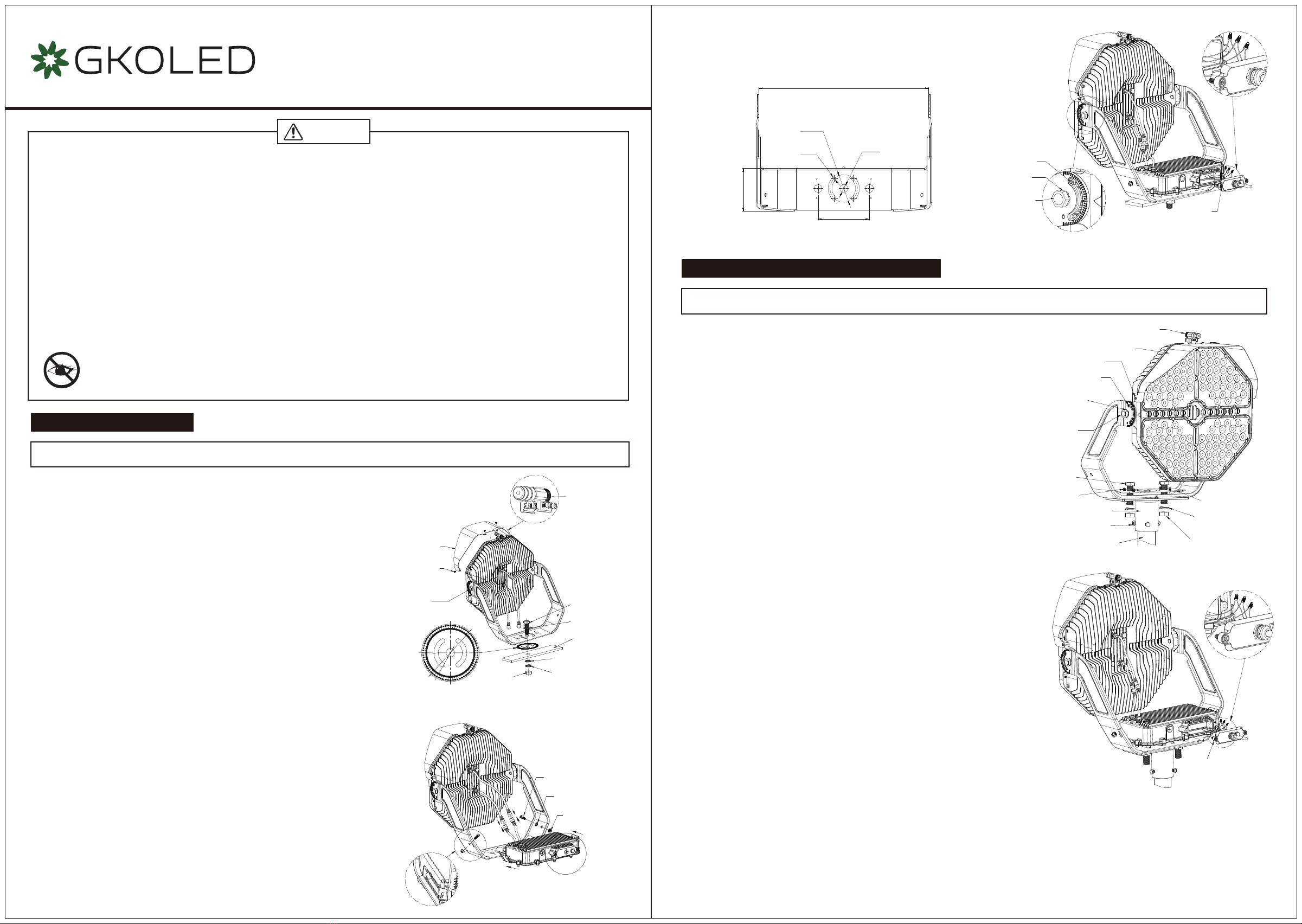
1. Secure the visor onto the top of the fixture with four PM5*8-SS screws (30-45
in-lbf (3.5 to 5 N-m)).
2. Loosen the two CM4*25 screws from the laser aiming sight, place the laser aiming
sight in the keyhole slots at the top of the fixture and tighten the two CM4*25
screws (30-45 in-lbf (3.5 to 5 N-m)).
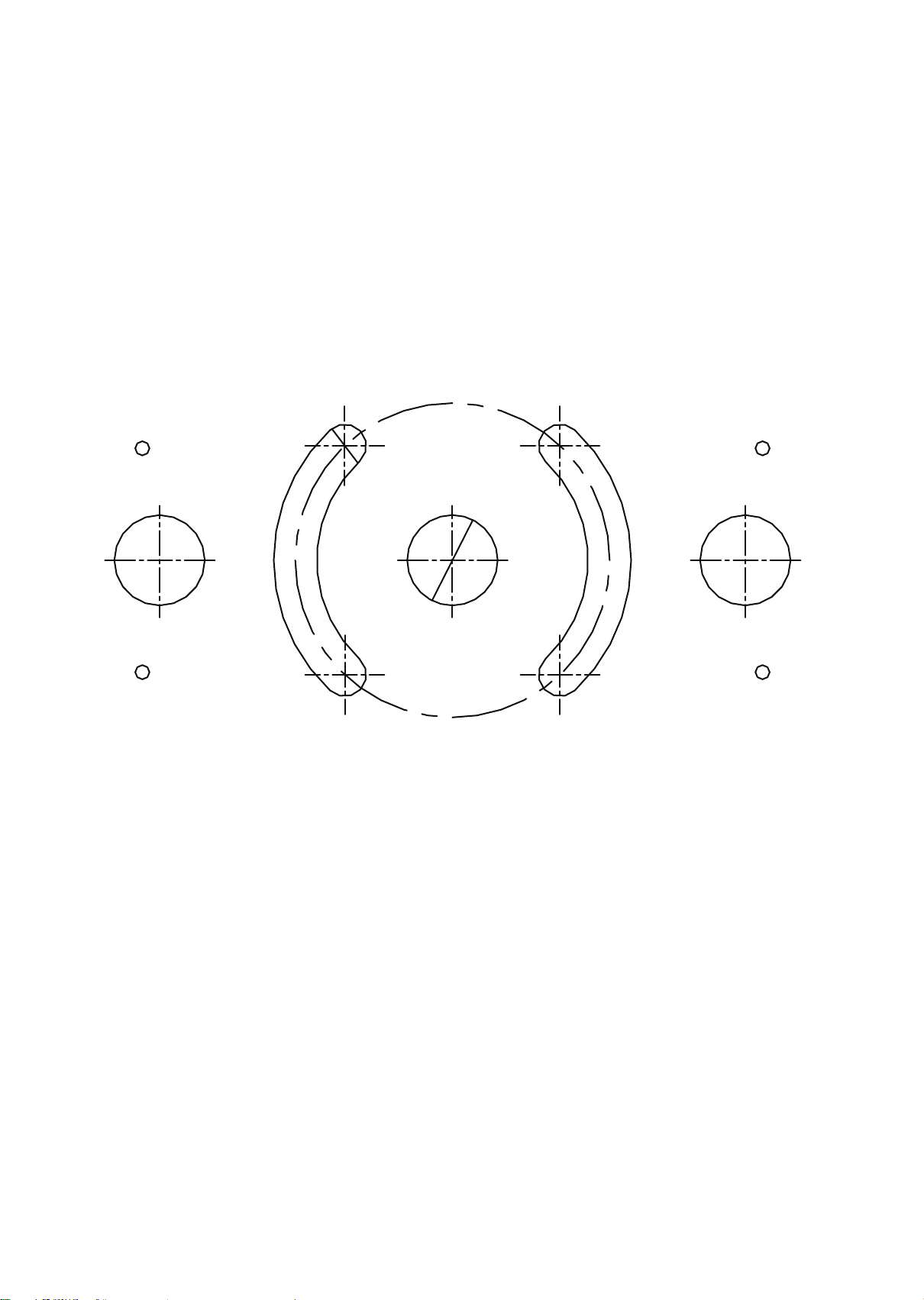
3. Drill a knockout on the mounting structure using the size of the knockout on the
mounting bracket as a guide.
4. Align the center hole of the horizontal aiming protractor and the mounting bracket
and attach the horizontal aiming protractor to the mounting structure.
5. Align the knockout in the mounting bracket to the knockout previously made in the
mounting structure and install the 3/4in. bolt, 3/4in. flat washers, 3/4in. spring
washer, and 3/4in. nut to securely fasten the fixture mounting bracket to the
mounting structure as shown in the diagram. (58.5 N-m). Do not fully tighten the
hardware until the fixture is aimed to the desired angle, just make sure the fixture is
secure.
6. Slightly loosen the fixture aiming screws on the side of the mounting bracket just
enough to allow the fixture to rotate and tilt. Use the horizontal aiming protractor
and laser aiming sight to aim the fixture according to specific lighting requirements.
After aiming is complete, tighten the M16*35-SS screws on the sides of the fixture
(43.8 N-m) and all other bolts and screws including hex screws (26-33 ft-lbf (35 to
45 N-m)) and CM16*15-SS set screws (7.9 N-m) on the side of the fixture, as well
as the mounting hardware.
7. Set the driver box on the mounting bracket so that the screw holes on the sides of
the driver box align with the mounting holes on the bracket, ensuring the side with
the driver output cables is facing up. Install the two CM8*20 screws, washers, and
nuts to securely fasten the driver box to the mounting bracket (35-75 in-lbs (4-8
N-m)). Ensure that the driver box being installed on the light head matches the
power configuration (wattage and voltage) of the light head. DO NOT install the
driver box on a light head with a different power configuration. Failure to properly
match the driver box and light head can damage the fixture.
8. Connect the output cables from the driver box to the light engine cables from the
light head through the waterproof connectors. Insert the the two parts of the
connectors together and tighten the screw, making sure that the seal is water-tight.
9. Remove one of the indicated 1/2" screw plugs from the back of the driver box, then
remove the driver box cover, pass the input wire trough the cover making sure to
use a sufficiently long wire, and secure it with a metal waterproof connector (not
included). Make all necessary wiring connections according to the wiring diagram
on the last page, making sure to observe proper voltage and polarity.
Installation Guide (Default)
Installation and service of luminaires should only be performed by a qualified licensed electrician.
Loosen 2 CM4*25
from the Laser
Aiming Sight
Horizontal
Aiming Protractor
Visor
3/4in.
Bolt
3/4in.
Flat Washers
3/4in.
Flat Washers
3/4in.
Spring Washers
CM8*20-SS
Screw
CM6*15-SS
Screw
M8-SS
Toothed
Washers
M8-SS
Nut
3/4in.
Nut
Mounting
Structure
PM5*8-SS
Screw
Φ5.83in.
(148mm.)
Φ0.87in.
(22mm.)
CM6*15-SS
Screw
CM6*15-SS
17.7in. (450mm.)
5.35in. (136mm.)
Screw
M16-SS
Toothed
Washers
M16*35-SS
Screw
1/2" Screw Plugs
for wiring
connections
4.49in. (114mm.)
Φ2.87in.
(73mm.)
Φ0.39in.
(10mm.)
Φ0.83in.
(21mm.)
Installation Guide (With Trunnion Adaptor)
1. Secure the mount bracket plate on the mounting bracket with four KM4*12-SS
screws (30-45 in-lbf (3.5 to 5 N-m)).
2. Secure the visor onto the top of the fixture with four PM5*8-SS screws (30-45
in-lbf (3.5 to 5 N-m)).
3. Secure the trunnion adaptor on the mounting bracket with two 3/4in. bolts,
spring washers, and nuts (35-45 ft-lbf (47 to 60 N-m)), put the trunnion adaptor
on top of the 2-3/8" tenon, and lock it with the three 3/8 x 0.787 screws (17.7
N-m).
4. Loosen the two CM4*25 screws from the laser aiming sight, place the laser
aiming sight in the keyhole slots at the top of the fixture and tighten the two
CM4*25 screws (30-45 in-lbf (3.5 to 5 N-m)).
5. Slightly loosen the fixture aiming screws on the side of the mounting bracket just
enough to allow the fixture to rotate and tilt. Use the horizontal aiming protractor
and laser aiming sight to aim the fixture according to specific lighting
requirements. After aiming is complete, tighten the M16*35-SS screws on the
sides of the fixture (43.8 N-m) and all other bolts and screws including hex
screws (26-33 ft-lbf (35 to 45 N-m)) and CM16*15-SS set screws (7.9 N-m) on
the side of the fixture, as well as the mounting hardware.
6. Set the driver box on the mounting bracket so that the screw holes on the sides
of the driver box align with the mounting holes on the bracket, ensuring the side
with the driver output cables is facing up. Install the two CM8*20 screws,
washers, and nuts to securely fasten the driver box to the mounting bracket
(35-75 in-lbs (4-8 N-m)). Ensure that the driver box being installed on the light
head matches the power configuration (wattage and voltage) of the light head.
DO NOT install the driver box on a light head with a different power configuration.
Failure to properly match the driver box and light head can damage the fixture.
7. Connect the output cables from the driver box to the light engine cables from the
light head through the waterproof connectors. Insert the the two parts of the
connectors together and tighten the screw, making sure that the seal is
water-tight.
8. Remove one of the indicated 1/2" screw plugs from the back of the driver box,
then remove the driver box cover, pass the input wire trough the cover making
sure to use a sufficiently long wire, and secure it with a metal waterproof
connector (not included). Make all necessary wiring connections according to the
wiring diagram on the last page, making sure to observe proper voltage and
polarity.
9. Make sure that all wires are securely connected and that there are no exposed
conductors, then carefully push the wires into the driver box making sure the
wires do not get pinched. Reinstall the driver box cover (35-75 in-lbf (4-8 N-m)).
Installation and service of luminaires should only be performed by a qualified licensed electrician.
M16*35-SS
Screw
10. Make sure that all wires are securely connected and that there are no exposed
conductors, then carefully push the wires into the driver box making sure the
wires do not get pinched. Reinstall the driver box cover (35-75 in-lbf (4-8 N-m)).
Aiming Assembly
Visor
PM5*8-SS
Screw
CM6*15-SS
Screw
M16*35-SS
Screw
3/4in.
Bolt
KM4*12-SS
Screw
3/8*0.787
UNC Screw
2-3/8" Tenon
3/4in. Nut
Mount Bracket Plate
3/4in.
Spring Washer
Yoke Adaptor
M16-SS
Toothed
Washers