P-LUX UNIT
FIGURE 3
INSTALLATION - Continued
2.
3.
4.
5.
Using the backplate as a template
mark positions for fixing holes and
cable entry. Use the built in spirit
level to ensure the backplate is
straight.
If fixing to masonry, drill the fixing
holes 25mm deep and insert
masonry plugs so they are flush
with the surface (Figure 1).
Pierce a hole in the grommet and
push the mains cable through
allowing enough cable for
connection to the terminal block
(Figure 2).
Fix the backplate to the mounting
surface with the fixing screws
(Figures 1 and 2).
Remove the pull out connector from the fitting.
Connect the mains supply to the pull out connector using the following colour code for the wiring
(Figures 2 and 3).
Connect the wire coloured Brown or Red (Live) to the terminal marked L.
Connect the wire coloured Green/Yellow or Green (Earth) to the terminal marked Eor .
Connect the wire coloured Blue or Black (Neutral) to the terminal marked N.
Once wired push the connector back into the slot in the fitting.
FIGURE 2
L N
INSTALLATION - Continued
P-LUX UNIT
FIGURE 3
INSTALLATION - Continued
2.
3.
4.
5.
Using the backplate as a template
mark positions for fixing holes and
cable entry. Use the built in spirit
level to ensure the backplate is
straight.
If fixing to masonry, drill the fixing
holes 25mm deep and insert
masonry plugs so they are flush
with the surface (Figure 1).
Pierce a hole in the grommet and
push the mains cable through
allowing enough cable for
connection to the terminal block
(Figure 2).
Fix the backplate to the mounting
surface with the fixing screws
(Figures 1 and 2).
Remove the pull out connector from the fitting.
Connect the mains supply to the pull out connector using the following colour code for the wiring
(Figures 2 and 3).
Connect the wire coloured Brown or Red (Live) to the terminal marked L.
Connect the wire coloured Green/Yellow or Green (Earth) to the terminal marked Eor .
Connect the wire coloured Blue or Black (Neutral) to the terminal marked N.
Once wired push the connector back into the slot in the fitting.
FIGURE 2
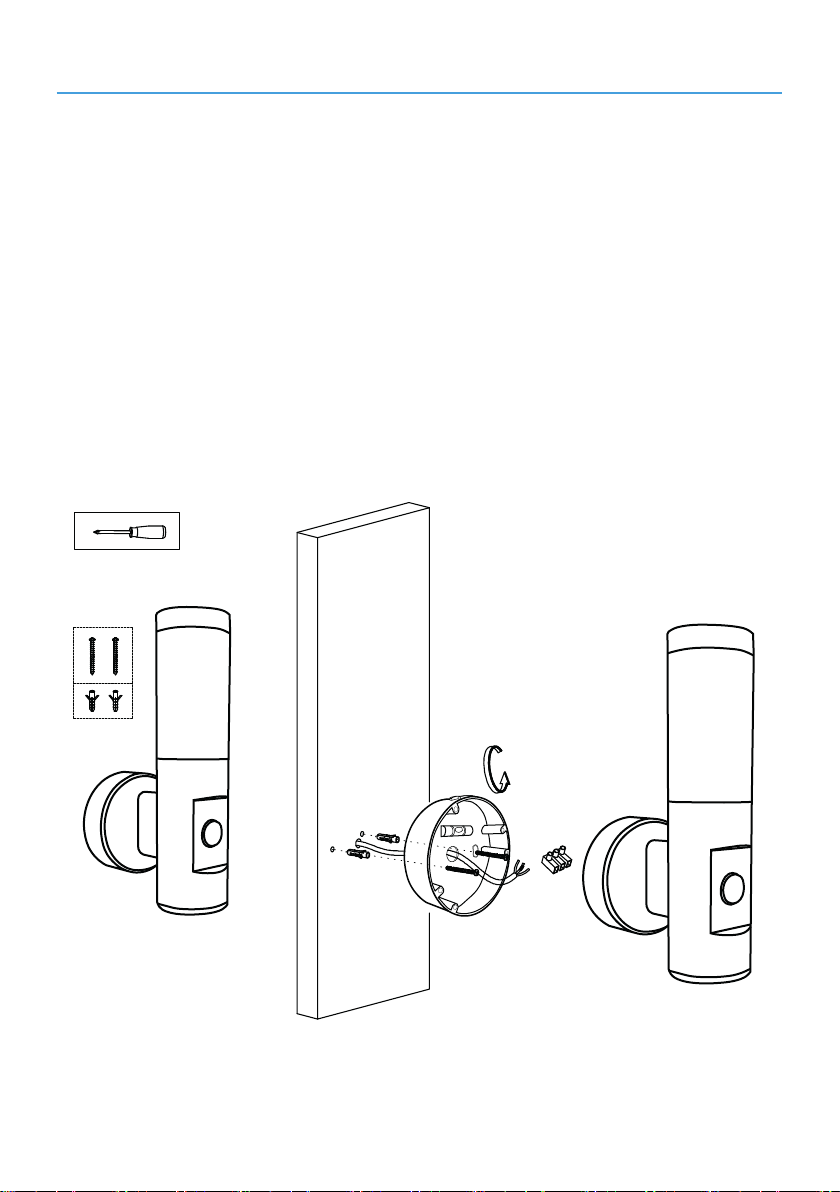
2. Using the backplate as a template mark positions
for xing holes and cable entry. Use the built in
spirit level to ensure the backplate is straight.
If xing to masonry, drill the xing holes 25mm
deep and insert masonry plugs so they are ush
with the surface (Figure 1).
3. Pierce a hole in the grommet and push the mains
able through allowing enough cable for
connection to the terminal block (Figure 2).
4. Fix the backplate to the mounting surface with
the xing screws
(Figures 1 and 2).
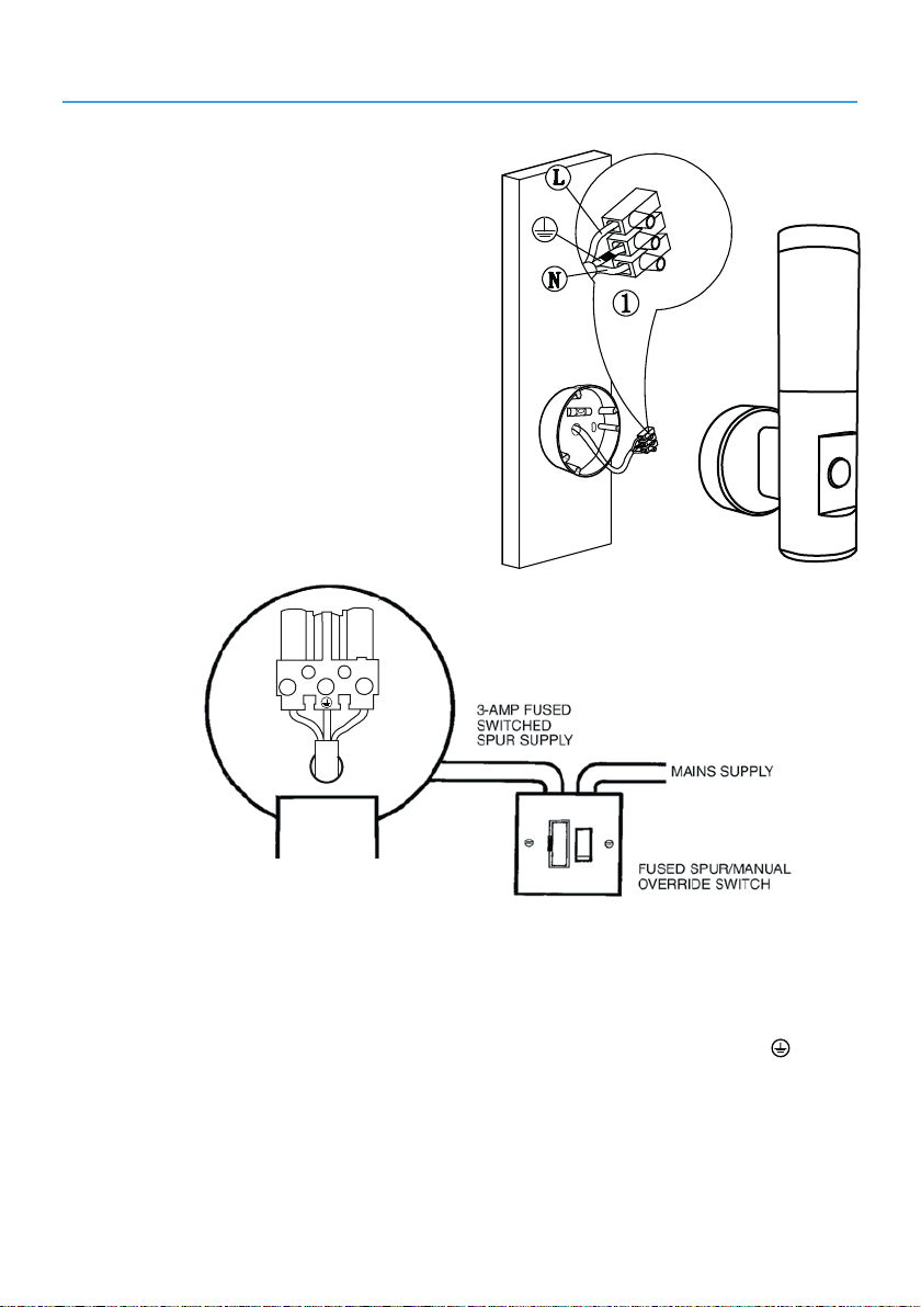
5. Remove the pull out connector from the tting.
Connect the mains supply to the pull out connector using the following colour code for the
wiring (Figures 2 and 3).
Connect the wire coloured Brown or Red (Live) to the terminal marked L.
Connect the wire coloured Green/Yellow or Green (Earth) to the terminal marked E or .
Connect the wire coloured Blue or Black (Neutral) to the terminal marked N.
Once wired push the connector back into the slot in the tting