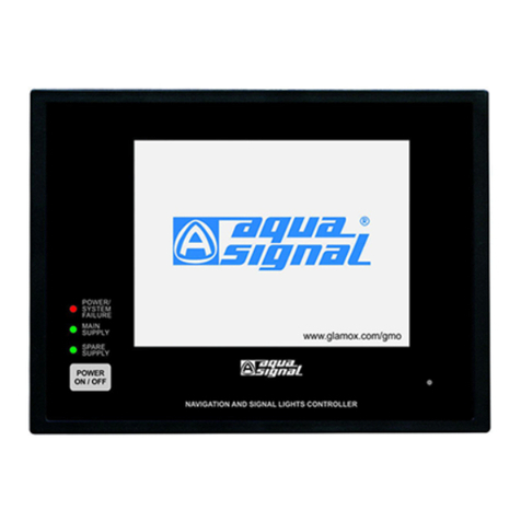
Glamox NL95 User manual

Rev.: 4, Print date: 2021-05-05
NL95
Touch Screen Navigational Light Controller
NL95
User manual

Rev.: 4, Print date: 2021-05-05
NL95

Rev.: 4, Print date: 2021-05-05
NL95
Date/
Sign
Changes
0
Rev
Preliminary
1DIN rail dimension 2021.02.17.MK
2Main unit dimension, note for cables 2021.03.17.MK
3add 5-D and 13-S modules 2021.03.29.MK
4Remote protocol 2021.05.05.MK

Rev.: 4, Print date: 2021-05-05
NL95
1. Overview
1.1 Description
1.2 Design
1.3 Package contents
1.4 Installation and configuration procedure
2. Safety instructions
3. Installation
3.1 Installation requirements
3.1.1 Arrangement
3.1.2 Connection
3.2 Preparation
3.3 Mounting
3.3.1 Main unit
3.3.2 Power Supply and Input modules
3.4 Connecting
3.4.1 Connecting protective earth
3.4.2 Interconnecting modules
3.4.3 Connecting lights circuits
3.4.4 Connecting power supply
3.4.5 Conecting input/output contacts and NMEAcommunication
3.4.6 NMEAcommunication protocol
3.4.7 Powering up
4. Configuration
4.1 Configuration
4.2 Enter / Exit configuration mode
4.3 Configuration screens
5. Operating instructions
5.1 Normal operation mode
5.2 Manual operation mode
6. Commissioning
6.1 Commisioning procedure
6.2 Configuration setup form
7. Technical characteristics
7.1 Outlines / codes
8. Troubleshooting
9.Appendix
9.1 Project information form
9.2 Configuration setup form
9.3 Remote control MODBUS RTU supported parameters
9.4 Remote control RS485 and RS232 connection

Rev.: 4, Print date: 2021-05-05
1
NL95
1. Overview
- Color TFT display with touch panel
- Automatic switch-over to spare light
in case of main navigation light
malfunction
- Independent lights circuit connection
and light presentation on display.
- Switch on group of lights
by single button
- Switch off all lights by single button
- LED lights can be connected
- Modules interconnections via
original cables with connectors
1.1 Description
NL95 is a programmable control and monitoring system for navigation and signal lights. Built-in software
allows easy programming of lights configuration in main unit itself without requirement of external devices.
Modular construction makes it suitable for all ships / vessels types and sizes, with remote control feature it is
possible to integrate it with ship control system. The NL95 main unit is equipped with touch screen display, and
runs user-friendly, easy operating software.
It is available in 230 V ac, 115 V ac, or 24 V dc version depending on lights power supply. All versions
have dual power supply input (main and emergency) with automatic change-over.
NL95 continuously monitors status of lights that are switched on and light's circuitry by checking current
consumption. If current drops bellow threshold, alarm is activated and system automatically switches to
spare light (if exists), this provides more safety. Each light input is protected by double pole fuse.
Input modules are equipped with manual activation feature which allows operation even in case of
electronic failure.
NL95 maximum configuration controls up to 80 lights, i.e 30 double lights and 20 single or up to 50 single
lights.
NL95 tested and compatible with standard bulbs and Glamox / Aquasignal LED navigation lights series
60, 61, 65, 65Arctic, and series 75.
- Fully programmable lights presentation
properties (name, number, color,
shape, position, spare light existence)
POWER ON
FAILURE F1
NL95 Touch screen Navigational Light Controller

Rev.: 4, Print date: 2021-05-05
2
NL95
ITNL-10-D (up to 3 pcs.)
INPUT MODULE FOR 10 DOUBLE
LIGHTS
ITNL-10-S (up to 5 pcs)
INPUT MODULE FOR 10 SINGLE
LIGHTS (OR 5 DOUBLE LIGHTS)
1 - Original cable 2.5 m long
(pls. check connection diagram)
2 - Original cables 1.5 m long
(pls. check connection diagram)
ITNSLP-01P
POWER SUPPLY MODULE
ITNSL-01TP
MAIN UNIT
NL95 comprises of 3 main parts: Main unit, Power Supply module, and Input modules.
- Main unit provides user interface for complete system, monitors operation of Power Supply and Input
modules. In case of failure detection, it alarms operator. Main unit contains complete lights configuration
as well as information of modules connected to it.
- Power Supply module provides power supply for lights as well as internal power supply for main unit
and modules. It is equipped with automatic change-over between main and emergency power supply. It
includes external alarm output contact, input contact for external alarm accept, and NMEA 0183 2-way
comunnication with other systems. Module comes in three versions 230 V ac, 115 V ac or 24 V dc.
- Input modules operate and control the lights. In case of malfunction or alarm detection, alarm is sent
to the main unit. All light inputs circuits are double fused. Manual light activation is possible in case of
electronic failure. Number and type of the Input modules depends on necessary configuration for each
specific ship.
There are two basic Input modules types:
- Double lights module for controlling double lights. Double lights module includes main and spare input
for each double light, double light consists of two parts: main and spare. Switching between main and
spare light is automatic. Module can also be used for single lights however in that case only main light
input is used. Available modules are ITNL-10-D-230 for 10 double lights on 230 V ac or 115 V ac
(depending on power supply module version) and ITNL-10-D-24 for 10 double lights on 24 V dc.
- Single lights module for controlling single lights. Each light is connected to each light input. Module
can also be used for controlling double lights, however in that case each double light is connected to 2
inputs - one for main light and one for spare light. Available modules are ITNL-10-S-230 for controlling
10 single (or 5 double) lights on 230 V ac or 115 V ac power supply (depending on power supply module
version) and ITNL-10-S-24 for 10 single lights (or 5 double lights) on 24 V dc.
System configuration:
- Up to 5 Input modules (in total) can be installed
- Up to 3 pcs ot ITNL-10-D (double lights)
- Up to 5 pcs of ITNL-10-S (single lights)
- ITNL-10-D and ITNL-10-S can be combined in the same system
- Maximum number of lights : 80 ( in configuration: 30 double lights and 20 single lights)
2
POWER ON
FAILURE F1
CON1 CON2
MAIN UNIT
ITNSL-01TP
CON1 CON2
CON3
AUDIO ALARM ACCEPT INPUT
AL2
2 3 4 5 6 7 8 9 10 12 13 14 15 161
AL1 AL3SYS
C.O. VOLTAGE-FREE OUTPUT CONTACT
18 19 2017 21
SYSTEM OPERATING
COMMON ALARM OUTPUT
B A B A -
RX TX
NMEA 0183
RECIEVER
NMEA 0183
TRANSMITTER
CON3
INPUT
MODULES
2
1

Rev.: 4, Print date: 2021-05-05
3
NL95
1.2 Design
2
1“POWER ON/OFF”,
power on / power off system
FAILURE - LED indicates when ON :
(a) System total power supply failure
(b) Communication error between main unit
and Power Supply module
3
POWER ON - LED indicates when:
(a) ON - system is operating
(b) Blinking - System is powering up / booting
Buzzer
4
F2 key - for adjusting display intensity,
configurable via
CONFIG > PREFERENCES > F2 KEY
5
F1 key - general use key,
configurable via
CONFIG > PREFERENCES > F1 KEY
6
Touch screen display
7
MAIN UNIT ITNSL-01TP
F1
11
14
10
12
8
Back View
9
POWER ON
FAILURE F1
Front View
1 2 3 4 51 6 7
13
8
9
10
11
12
Main unit label
Holders for fixing cables
Modbus RTU over TCP/IP RJ45 Cable input
Earth bolt
Mounting screws
DB9 connectors for inteface
with Power Supply module
13
14
End of line termination resistor dip switch
15
16
USB type A input port, for upload and download
15
SD card input slot, for upload and download
16

Rev.: 4, Print date: 2021-05-05
4
NL95
1 7
82
93
104
5
6
Input fuse, 0.2AF
Switches for manual light operation
RJ45 connector - from previous module
RJ45 connector - to next module
Input module power supply terminals TS35 rail for mounting
Fuses for lights, 1AF
11
Input terminals for lights connection
1
2
8
3
4
5
Input fuse for main power supply
Module label
Input fuse for emergency power supply
9Terminals for NMEA 0183 communication
Power supply output for Input modules
10 TS35 rail for mounting
Output contacts for system operating / alarms
DB9 connectors for main unit connection
6RJ45 connector for Input module connection
7Input terminals for audio alarms silence
End of line termination resistor dip switch
Address selection dip switch
Module label, with addressing table
1 3 59 10 11
46
278
1 2 3 5 6 7 8 9
410
CON1 CON2
MAIN UNIT
ITNSL-01TP
CON1 CON2
CON3
AUDIO ALARM ACCEPT INPUT
AL2
2 3 4 5 6 7 8 9 10 12 13 14 15 161
AL1 AL3SYS
C.O. VOLTAGE-FREE OUTPUT CONTACT
18 19 2017 21
SYSTEM OPERATING
COMMON ALARM OUTPUT
B A B A -
RX TX
NMEA 0183
RECIEVER
NMEA 0183
TRANSMITTER
CON3
INPUT
MODULES

Rev.: 4, Print date: 2021-05-05
5
NL95
1 7
82
93
104
5
6
Input fuse, 0.63AF
Switches for manual light operation
RJ45 connector - from previous module
RJ45 connector - to next module
Input module power supply terminals TS35 rail for mounting
Fuses for lights, 2AF
11
Input terminals for lights connection
1
2
8
3
4
5
Terminals for main power supply
Module label
Terminals for emergency power supply
9Terminals for NMEA 0183 communication
Power supply output for Input modules
10 TS35 rail for mounting
Output contacts for system operating / alarms
DB9 connectors for main unit connection
6RJ45 connector for Input module connection
7Input terminals for audio alarm silence
INPUT MODULE ITNL-10-D-24 / ITNL-10-S-24 (24 V dc)
End of line termination resistor dip switch
Module label, with addressing table
Address selection dip switch
1 2 3 5 6 7 8 9
410
ITNSLP-01P
CODE
POWER SUPPLY MODULE
S/N
OUT1
24V DC output
for MODULES
-
61
+
60 49
+
60
-
61 49 49 49 49
OUT2
24V DC output
for MODULES
-
61
+
60
+
60
-
61
CON1 CON2
MAIN UNIT
ITNSL-01TP
CON1 CON2
CON3
AUDIO ALARM ACCEPT INPUT
AL2
2 3 4 5 6 7 8 9 10 12 13 14 15 161
AL1 AL3SYS
C.O. VOLTAGE-FREE OUTPUT CONTACT
18 19 2017 21
SYSTEM OPERATING
COMMON ALARM OUTPUT
B A B A -
RX TX
NMEA 0183
RECIEVER
NMEA 0183
TRANSMITTER
CON3
INPUT
MODULES
1 3 59 10 11
46
278
ITNL-10-D-24
CODE
NAVIG. LIGHTS MODULE
+
60
-
61
49
CON 1
CON 2
24V DC
From
previous
module
To next
module
MODULE
ADDRESS
S/N
1 2
1
2
3
4
ON
OFF

Rev.: 4, Print date: 2021-05-05
6
NL95
Main unit type ITNSL-01TPManual
Power Supply module Original cable DB9 2.5m long for
Main unit connection
Original cable RJ45 1.5m long for
Input module connection
Input module
Spare parts
set
Code Figure / name
Following components included in the product package.
1. Familiarise with the safety instructions
2. Check installation requirements
3. Make installation plan
4. Install Navigation and Signal Lights Controller
5. Connect the equipotential bonding
6. Connect lights
7. Connect the power supply
8. Configure or load configurations
9. Check operation
10. Fill in commisioning form and backup configuration
1.3 Package contents
1.4 Installation and configuration procedure
02-04-211
02-04-212
02-04-213
02-04-214
02-04-215
02-04-219
02-04-216
02-04-220
02-04-217
02-04-221
02-04-218
02-04-222
POWER ON
FAILURE F1
CON1 CON2
MAIN UNIT
ITNSL-01TP
CON1 CON2
CON3
AUDIO ALARM ACCEPT INPUT
AL2
2 3 4 5 6 7 8 9 10 12 13 14 15 161
AL1 AL3SYS
C.O. VOLTAGE-FREE OUTPUT CONTACT
18 19 2017 21
SYSTEM OPERATING
COMMON ALARM OUTPUT
B A B A -
RX TX
NMEA 0183
RECIEVER
NMEA 0183
TRANSMITTER
CON3
INPUT
MODULES

Rev.: 4, Print date: 2021-05-05
7
NL95
System contains dangerous voltages when connected to line voltages. Only a
competent technician should carry out the installation / service.
IMPORTANT!!!
Navigation and Signal Lights Controller needs to be installed in accordance with rules and
regulations of classification societies as well as in accordance with good electrotechnical
practice.
Use of non appropriate lights could lead to irregular operation of Navigation and Signal Lights
Controller and navigation lights which could indanger safe navigation of the ship. Special
precautions need to be taken to check the compatibility of non-bulb and non-Glamox LED
lights.
Operating manual of used navigation and signal lights needs to be considered.
2. Safety instructions
Do not touch the electrical parts when power supply line is connected.
While repairs or inspection is made, the power supply line must be disconnected.
"POWER ON/OFF” switch does not disconnect the power supply line. Power
supply line is still present on terminals, Power Supply module, and Input
modules.
Navigation and Signal Lights Controller is open equipment. That is, equipment may
only be installed in consoles and cabinets which provide front panel access for
operating devices (main unit). Power Supply and Input modules must be easily
reachable in case of manual operation of lights.
For manual operating of lights special precautions needs to be taken in order that
“live parts” are not touched. For manual operation of lights use only insulated
screwdriver.

Rev.: 4, Print date: 2021-05-05
8
NL95
11
2
3
45
6
7
8
9
10 11
13
12
14 15
1716
18
19
1PS SB
1
2
3
45
6
7
8
9
10 11
13
12
14 15
1716
18
19

Rev.: 4, Print date: 2021-05-05
9
NL95
3.1.2 Connection
IMPORTANT!!! Requirements of navigation and signal lights that are going to be used with Navigation and Signal Lights Controller need
to be considered. Navigation and signal lights operating manual should be read before continuing. Check technical characteristics
of each light module.
CON1
CON2
Original
cable
2.5m
long
CON3
CON2
CON1
1
3
1
3
MAIN
50
50
51
51
49
49
L
L
N
N
1
2
3
4
+24V
IN1
IN2
IN3
AUDIO ALARM
ACCEPT INPUT
1
2
MAIN
EMERG
SYSTEM OPERATING
C.O. VOLTAGE-FREE
OUTPUT CONTACT
5
8
11
14
6
9
12
15
7
10
13
16
COMMON ALARM OUTPUT
C.O. VOLTAGE-FREE
OUTPUT CONTACT
19
17
20
18
21
NMEA 0183 RECEIVER
input, ($--ACK sentence)
NMEA 0183 TRANSMITTER
output, ($NLALR sentence)
Rx-B
Rx-A
Tx-B
Tx-A
-
AL1
SYS
AL2
AL3
MAIN
MAIN
MAIN
MAIN
MAIN
MAIN
MAIN
MAIN
MAIN
INPUT MODULE
ITNL-10-D-230
CON1
CON2
1
21
2
22
3
23
4
24
5
25
8
28
11
31
14
34
6
26
9
29
12
32
15
35
17
37
19
39
7
27
10
30
13
33
16
36
18
38
20
40
LIGHT
No.1
LIGHT
No.2
LIGHT
No.3
LIGHT
No.4
LIGHT
No.5
LIGHT
No.6
LIGHT
No.7
LIGHT
No.8
LIGHT
No.9
LIGHT
No.10
50
50
51
51
49
49
L
L
N
N
MAIN
ADDRESS
ON
1 2
MAIN
MAIN
MAIN
MAIN
MAIN
MAIN
MAIN
MAIN
MAIN
INPUT MODULE
ITNL-10-D-230
CON1
CON2
1
21
2
22
3
23
4
24
5
25
8
28
11
31
14
34
6
26
9
29
12
32
15
35
17
37
19
39
7
27
10
30
13
33
16
36
18
38
20
40
LIGHT
No.1
LIGHT
No.2
LIGHT
No.3
LIGHT
No.4
LIGHT
No.5
LIGHT
No.6
LIGHT
No.7
LIGHT
No.8
LIGHT
No.9
LIGHT
No.10
50
50
51
51
49
49
L
L
N
N
MAIN
ADDRESS
ON
1 2
INPUT MODULE
ITNL-10-S-230
CON1
CON2
1
2
3
4
5
8
11
14
6
9
12
15
17
19
7
10
13
16
18
20
LIGHT
No.1
LIGHT
No.2
LIGHT
No.3
LIGHT
No.4
LIGHT
No.5
LIGHT
No.6
LIGHT
No.7
LIGHT
No.8
LIGHT
No.9
LIGHT
No.10
50
50
51
51
49
49
L
L
N
N
ADDRESS
ON
1 2 4 8
INPUT MODULE
ITNL-10-S-230
CON1
CON2
1
2
3
4
5
8
11
14
6
9
12
15
17
19
7
10
13
16
18
20
LIGHT
No.1
LIGHT
No.2
LIGHT
No.3
LIGHT
No.4
LIGHT
No.5
LIGHT
No.6
LIGHT
No.7
LIGHT
No.8
LIGHT
No.9
LIGHT
No.10
50
50
51
51
49
49
L
L
N
N
ADDRESS
ON
1 2 4 8 1
2
1
2
1
2
1
2
1
2
1
2
1
2
Original cable 1.5m long*Original cable 1.5m long*Original cable 1.5m long*
Interconncetions between modules
All original cables are cables for communication and
have to be routed in accordance with rules and good
marine practice. Have to be seperated from power
cables which can cause high level of interference.
*Do not route together with power cables
RJ45
Remote Control
Modbus RTU over TCP/IP
MAIN UNIT type
ITNSL-01TP

Rev.: 4, Print date: 2021-05-05
10
NL95
Cable/wires
2.5-4mm2** CON1
CON2
Original
cable
2.5m
long
CON3
CON2
CON1
MAIN POWER
SUPPLY
24VDC
EMERGENCY
POWER SUPPLY
24VDC
1
2
3
4
+24V
IN1
IN2
IN3
AUDIO ALARM
ACCEPT INPUT
60
61
60
61
49
+
-
+
-
1
2
MAIN
EMERG
SYSTEM OPERATING
C.O. VOLTAGE-FREE
OUTPUT CONTACT
5
8
11
14
6
9
12
15
7
10
13
16
COMMON ALARM OUTPUT
C.O. VOLTAGE-FREE
OUTPUT CONTACT
19
17
20
18
21
NMEA 0183 RECEIVER
input, ($--ACK sentence)
NMEA 0183 TRANSMITTER
output, ($NLALR sentence)
Rx-B
Rx-A
Tx-B
Tx-A
-
AL1
SYS
AL2
AL3
MAIN
MAIN
MAIN
MAIN
MAIN
MAIN
MAIN
MAIN
MAIN
INPUT MODULE
ITNL-10-D-24
CON1
CON2
1
21
2
22
3
23
4
24
5
25
8
28
11
31
14
34
6
26
9
29
12
32
15
35
17
37
19
39
7
27
10
30
13
33
16
36
18
38
20
40
LIGHT
No.1
LIGHT
No.2
LIGHT
No.3
LIGHT
No.4
LIGHT
No.5
LIGHT
No.6
LIGHT
No.7
LIGHT
No.8
LIGHT
No.9
LIGHT
No.10
MAIN
ADDRESS
ON
1 2
MAIN
MAIN
MAIN
MAIN
MAIN
MAIN
MAIN
MAIN
MAIN
INPUT MODULE
ITNL-10-D-24
CON1
CON2
1
21
2
22
3
23
4
24
5
25
8
28
11
31
14
34
6
26
9
29
12
32
15
35
17
37
19
39
7
27
10
30
13
33
16
36
18
38
20
40
LIGHT
No.1
LIGHT
No.2
LIGHT
No.3
LIGHT
No.4
LIGHT
No.5
LIGHT
No.6
LIGHT
No.7
LIGHT
No.8
LIGHT
No.9
LIGHT
No.10
MAIN
ADDRESS
ON
1 2
INPUT MODULE
ITNL-10-S-24
CON1
CON2
1
2
3
4
5
8
11
14
6
9
12
15
17
19
7
10
13
16
18
20
LIGHT
No.1
LIGHT
No.2
LIGHT
No.3
LIGHT
No.4
LIGHT
No.5
LIGHT
No.6
LIGHT
No.7
LIGHT
No.8
LIGHT
No.9
LIGHT
No.10
ADDRESS
ON
1 2 4 8
INPUT MODULE
ITNL-10-S-24
CON1
CON2
1
2
3
4
5
8
11
14
6
9
12
15
17
19
7
10
13
16
18
20
LIGHT
No.1
LIGHT
No.2
LIGHT
No.3
LIGHT
No.4
LIGHT
No.5
LIGHT
No.6
LIGHT
No.7
LIGHT
No.8
LIGHT
No.9
LIGHT
No.10
ADDRESS
ON
1 2 4 8
1
2
1
2
1
2
1
2
1
2
1
2
Original
cable
1.5m
long*
Interconncetions between modules
All original cables are cables for communication and have to be routed in
accordance with rules and good marine practice. Have to be seperated
from power cables which can cause high level of interference.
* Do not route together with power cables
** To be calculated
3+
4-
3+
4-
1+
2-
1+
2-
3+
4-
3+
4-
1+
2-
1+
2-
60
60
61
61
49
49
+
+
-
-
60
60
61
61
49
49
+
+
-
-
60
60
61
61
49
49
+
+
-
-
60
60
61
61
49
49
+
+
-
-
1
2
Original
cable
1.5m
long*
Cable/
wires
2.5-4
mm2**
Cable/wires
2.5-4mm2**
CONNECTION - 24 V dc
OUT1
OUT2
MAIN UNIT type
ITNSL-01TP
RJ45
Remote Control
Modbus RTU over TCP/IP

Rev.: 4, Print date: 2021-05-05
11
NL95
Allow sufficient clearance of 20 mm around modules
Switches for manual activation, fuses and labels should
be clearly visible and accessible.
Console
Main
unit
Main unit cable -
original cable
2.5 m long
Power
Supply
module
Input
modules
Cable trays
Input module cable -
original cable
1.5 m long
Power Supply and Input modules
Allow suficient clearance around modules for mounting and for the connection of cables and wires.
Minimum distance 20 mm around modules. It is not recommended to route light cables together with power
cables.
Allow sufficient clearance around main unit for mounting as well as connection of cables and wires.
Minimum distance (x = 40 mm; y=40 mm; z=150 mm)
Do not install main unit near power cables!!!
It is not recommended to install main unit on direct sunlight.
The material in the area of the mounting cut-out must provide
sufficient strength to guarantee the enduring and safe mounting
of the main unit.
The force of fixing nut or operation of the main unit
must not lead to deformation of the material.
Main unit
Keep the supplied documentation and configuration file in a safe place. The documents belong to the
Navigation and Signal Lights Controller may be required for subsequent commissioning.
Navigation and Signal Lights Conroller needs to be installed on the bridge, Main unit should be installed on
console in accordance with guidance notes on ergonomic desgin and navigation bridges. Power Supply
and Input modules needs to be installed inside console. Modules need to be easily accessible for manual
operation of lights. Preferable arrangment shown in figure below:
xx
y
y
z
POWER ON
FAILURE F1
Main unit, Power Supply module, and Input Modules should have compass clearance of
minimum 85mm distance in all directions.

Rev.: 4, Print date: 2021-05-05
12
NL95
Arrangement
Following arrangement of Input modules needs to be followed:
- Up to 5 Input modules (in total) can be installed
- Up to 3 pcs ot ITNL-10-D or ITNL-5-D (double lights)
- Up to 5 pcs of ITNL-10-S or ITNL-13-S (single lights)
- ITNL-10-D and ITNL-10-S can be combined in the same system
- Maximum number of lights : 80 ( in configuration: 30 double lights and 20 single lights)
ITNL-10-D or ITNL-10-S,
Address 1
ITNL-10-D or ITNL-10-S,
Address 2
ITNL-10-D or ITNL-10-S,
Address 3
ITNL-10-S,
Address 4
ITNL-10-S,
Address 5
Input module ITNL address selection
ITNL Input module address is configurable by dip switches located on module
1- Address selection should be done when module is not connected, or system is powered off
2- Module addresses must not be duplicated.
When addressing please consult with prepared connection diagram.
This applies to 230 V ac, 115 V ac as well as 24 V dc ITNL modules.
ITNL address tables
Module type ITNL-10-D
MODULE
ADDRESS
1
2
3
4
1 2
ON
OFF
1 2
ON
OFF
1 2
ON
OFF
1 2
ON
OFF
DIP
SWITCH
Module type ITNL-10-S / ITNL-5-D / ITNL-13-S
MODULE
ADDRESS
1
2
3
4
5
6
7
8
1 12 24 48 8
ON ON
OFF OFF
1 12 24 48 8
ON ON
OFF OFF
1 12 24 48 8
ON ON
OFF OFF
1 12 24 48 8
ON ON
OFF OFF
1 12 24 48 8
ON ON
OFF OFF
1 12 24 48 8
ON ON
OFF OFF
1 12 24 48 8
ON ON
OFF OFF
1 12 24 48 8
ON ON
OFF OFF
DIP
SWITCH DIP
SWITCH
MODULE
ADDRESS
9
10
11
12
13
14
15
16
1
1Adjust address of module,
- each module should have unique address
- use one of the combination in the table below
Module configured with address 16 shown in the photo
CON1 CON2
MAIN UNIT
ITNSL-01TP
CON1 CON2
CON3
AUDIO ALARM ACCEPT INPUT
AL2
2 3 4 5 6 7 8 9 10 12 13 14 15 161
AL1 AL3SYS
C.O. VOLTAGE-FREE OUTPUT CONTACT
18 19 2017 21
SYSTEM OPERATING
COMMON ALARM OUTPUT
B A B A -
RX TX
NMEA 0183
RECIEVER
NMEA 0183
TRANSMITTER
CON3
INPUT
MODULES
Shown 230/115 VAC modules
POWER ON
FAILURE F1

Rev.: 4, Print date: 2021-05-05
13
NL95
PANEL
CUT-OUT
3.3 Mounting
3.3.1 Main unit
Make cut-out according to section “7.1 Units outlines/ codes”
Insert main unit into cut-out.
2
3.3.2 Power Supply and Input modules
- Fixing main unit to console with 4 pcs of M5 nuts, mounted from the back of the console. Use lock washers.
- Check if the main unit is properly fixed
1
1
2
POWER ON
FAILURE F1
for bolts M6 for bolts M6

Rev.: 4, Print date: 2021-05-05
14
NL95
Main unit connected to Power Supply module via cables with DB9 connectors.
3.4 Connecting
Keep the following task sequence, when connecting Navigation and Signal Lights Controller :
1. Connect the protective earth
2. Interconnect all modules
3. Connect lights’ circuit
4. Connect power supply
5. Connect input / output contacts and communication
Shown 230/115 V ac modules
2
2.5 mm
CON1 CON2
MAIN UNIT
ITNSL-01TP
CON1 CON2
CON3
AUDIO ALARM ACCEPT INPUT
AL2
2 3 4 5 6 7 8 9 10 12 13 1415 161
AL1 AL3SYS
C.O. VOLTAGE-FREE OUTPUT CONTACT
18 19 2017 21
SYSTEM OPERATING
COMMON ALARM OUTPUT
B A B A -
RX TX
NMEA 0183
RECIEVER
NMEA 0183
TRANSMITTER
CON3
INPUT
MODULES
2
2.5 mm 2
2.5 mm
CON2
CON1
1
2
CON1
CON2
DB9 cables
1
2
Put connector in appropriate socket
Fix the connector screws
CON1 CON2
MAIN UNIT
ITNSL-01TP
CON1 CON2
CON3
AUDIO ALARM ACCEPT INPUT
AL2
2 3 4 5 6 7 8 9 10 12 13 1415 161
AL1 AL3SYS
C.O. VOLTAGE-FREE OUTPUT CONTACT
18 19 2017 21
SYSTEM OPERATING
COMMON ALARM OUTPUT
B A B A -
RX TX
NMEA 0183
RECIEVER
NMEA 0183
TRANSMITTER
CON3
INPUT
MODULES
Protective earth of navigation and signal light is not considered. If connection of protective earth is required, it
needs to be connected directly to protective earth circuit of ship and not through input modules.

Rev.: 4, Print date: 2021-05-05
15
NL95
Fix the cables with cable strips. Do not overstress the connectors. Minimum bending radius is 40 mm.
Connecting Power Supply with the Input modules - 24 V dc
Connecting Power Supply with the Input modules - 230 V ac (115 V ac)
CON3
1
2
CON2
CON1
CON2
CON1
TO
NEXT
UNIT
50 51
50 5150 51 50 5150 51
L
N
L
N
L
N
L
N
L
N
1
2
Put connector in socket
“CLICK”
CON1 CON2
MAIN UNIT
ITNSL-01TP
CON1 CON2
CON3
AUDIO ALARM ACCEPT INPUT
AL2
2 3 4 5 6 7 8 9 10 12 13 14 15 161
AL1 AL3SYS
C.O. VOLTAGE-FREE OUTPUT CONTACT
18 19 2017 21
SYSTEM OPERATING
COMMON ALARM OUTPUT
B A B A -
RX TX
NMEA 0183
RECIEVER
NMEA 0183
TRANSMITTER
CON3
INPUT
MODULES
ITNL-10-D-24
CODE
NAVIG. LIGHTS MODULE
+
60
-
61
24V DC
S/N
4
ITNL-10-D-24
CODE
NAVIG. LIGHTS MODULE
+
60
-
61
24V DC
S/N
4
CON3
1
2
CON2
CON1
TO
NEXT
UNIT
-+
-+
-
+
-
+
RJ45 cable
2“CLICK”
*connect outputs, OUT1 and OUT2, according to connection drawing
1Put connector in socket
-+
-
+
CON2
CON1
-+
-
+
24V
OUT1*
24V
OUT2*
ITNSLP-01 P
CODE
POWER SUPPLY MODULE
S/N
OUT1
24V DC output
for MODULES
-
61
+
60 49
+
60
-
61 49 49 49 49
OUT2
24V DC output
for MODULES
-
61
+
60
+
60
-
61
CON1 CON2
MAIN UNIT
ITNSL-01TP
CON1 CON2
CON3 21
CON3
INPUT
MODULES

Rev.: 4, Print date: 2021-05-05
16
NL95
1
3
L
N
1
3
L
N
Power Supply module
ITNSLP-01P, 230 V ac (115 V ac)
5
6
1
2
7
2. MAIN
3
8
2. SPARE*
4
910
12
3. MAIN
3. SPARE*
* For ITNL-10-D modules
** Depend on light type
Power Supply module
ITNSLP-01P, 24 V dc
PE**
1
2
PE
MAIN
SPARE
3
4
PE
1
2
PE
MAIN
SPARE
3
4
PE
PE**
PE
PE
1
2
3
4
PE
PE
12
+
-MAIN
POWER SUPPLY
3
4
+
-EMERGENCY
POWER SUPPLY
PE
16 mm2
MAIN
POWER SUPPLY
EMERGENCY
POWER SUPPLY
PE
16 mm2
PE
16 mm2
Before connecting, check power supply rating as well as Power Supply module voltage rating
3.4.3 Connecting lights circuits
IMPORTANT!!! Requirements of used navigation and signal lights, and Navigation and Signal Lights Controller
need to be considered. Navigation and signal lights operating manual should be read before continuing.
Navigation and signal lights should be connected according to the prepared connection drawings. Each light
must be connected to appropriate input. Connect cable sheild to equipotential bonding circuit. Wire size to be
according to light requirements. After connecting, mark lable with appropriate lights’ name.
Navigation and Signal Lights Controller power supply should be connected according to prepared connection
drawings. Power supply wires / cables need to be in accordance with systems’ power consumption.
Connect cable shield to equipotential bonding circuit.
Shown 230/115 V ac
module
Table of contents
Other Glamox Controllers manuals
Popular Controllers manuals by other brands

Phase Technologies
Phase Technologies SD Series quick start guide

Goldline
Goldline aqua trol user manual

Plast-O-Matic
Plast-O-Matic CAFE Series Installation, operation & maintenance instructions

NovaStar
NovaStar NovaPro UHD manual

System air
System air MTY installation instructions

AquaMetrix
AquaMetrix Shark user manual