RANCHO RS6583B User manual

88583 Rev E
Suspension System RS6583B
2013-2007 Chevrolet Silverado/GMC Sierra 1500
88583 Rev E

2
READ ALL INSTRUCTIONS THOROUGHLY FROM START TO FINISH BEFORE BEGINNING INSTALLATION
IMPORTANT NOTES!
WARNING: This suspension system will enhance the off-
road performance of your vehicle. It will handle differently,
both on and off-road, from a factory equipped passenger car
or truck. Extreme care must be used to prevent loss of
control or vehicle rollover during abrupt maneuvers. Failure
to drive this vehicle safely may result in serious injury or
death to the driver and passengers. ALWAYS WEAR your
seat belts, REDUCE your speed, and AVOID sharp turns
and other abrupt maneuvers.
A. To reduce front drive shaft vibration, a replacement
shaft (part No. 3194-9824) is available from: POWERTRAIN
INDUSTRIES 7532 Anthony Avenue, Garden Grove, CA
92841 1-800 798-4585. For vehicles equipped with the
Autoride (Air) Suspension Option, front shock RS99799
and rear relocator kit RS6202 must be installed.
B. Before installing this system, have the vehicle’s
alignment and frame checked by a certified technician. The
alignment must be within factory specifications and the
frame of the vehicle must be sound (no cracks, damage or
corrosion).
C. Do not install a body lift kit with this suspension system
or interchange Rancho components with parts from another
manufacturer. New Rancho shock absorbers are required
and must be purchased separately. Front shocks:
RS999786 or RS999799, Rear shocks: RS999297
D. Do not powdercoat, chrome, cadmium, or zinc plate any
of the components in this system. To change the
appearance of components, enamel paint can be applied
over the original coating.
E. Welding on a car creates an electrical charge
throughout the body and frame. Disconnect the vehicle’s
battery prior to any welding. Place welding ground clamps
as near as possible to the weld. When welding on the
frame, never use a vehicle suspension component as a
welding ground point.
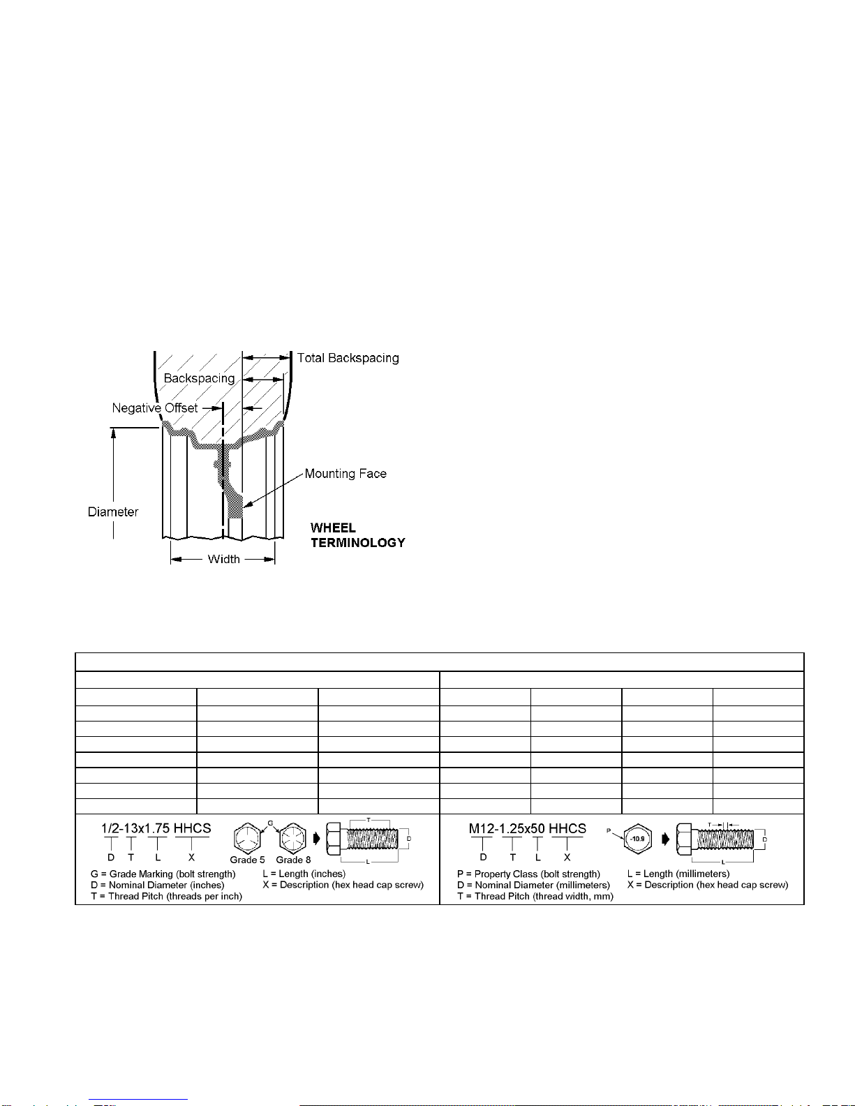
F. Each hardware kit in this system contains fasteners of
high strength and specific size. Do not mix hardware kits or
substitute a fastener of lesser strength. See bolt
identification table on page 2.
G. Compare the contents of this system with the parts list
in these instructions. If any parts are missing, contact the
Rancho Technical Department at 1-734-384-7804.
H. Install all nuts and bolts with a flat washer. When both
SAE (small OD) and USS (large OD) washers are used in a
fastener assembly, place the USS washer against the
slotted hole and the SAE washer against the round hole.
I. Apply a drop of thread locking compound to all bolts
during installation. CAUTION: Thread locking compound
may irritate sensitive skin. Read warning label on container
before use.
J. Unless otherwise specified, tighten all nuts and bolts to
the standard torque specifications shown in the table below.
USE A TORQUE WRENCH for accurate measurements.
K. Some of the service procedures require the use of
special tools designed for specific procedures. The following
tools and supplies are recommended for proper installation
of this system:
Chevrolet Service Manual
Coil Spring Compressor
Die Grinder
Drill motor
Assorted Drills: 1/8" through 1/2"
Torque Wrench (250 FT-LB capacity)
1/2” Drive Ratchet and Sockets
Assorted Combination Wrenches
Heavy Duty Jack Stands
Wheel Chocks (wooden blocks)
Hydraulic Floor Jack
Center punch
File
Reciprocating Saw (to modify frame)
Hammer
Wire Brush (to clean bracket mounting surfaces)
Silicone Spray Lubricant
Brake fluid
Tape Measure
Safety Glasses (wear safety glasses at all times)
L. It is extremely important to replace torsion bars, CV
flanges, and front drive shaft/pinion relationships as original.
Be sure to mark left/right, front/rear, and indexing of mating
parts before disassembly. A paint marker or light colored
nail polish is handy for this.
M. Suspension components that use rubber or urethane
bushings should be tightened with the vehicle at normal ride
height. This will prevent premature failure of the bushing
and maintain ride comfort.

3
N. The required installation time for this system is
approximately 8 hours. Check off the box ( ) at the
beginning of each step when you finish it. Then when you
stop during the installation, it will be easier to find where you
need to continue from.
O. This suspension system was developed using the
following tire & wheel combination: BFG All Terrain™
315/70 R17 tire, 17 x 8 wheel with 5.5 inches of wheel
backspacing. Total backspacing is 6.5 inches. Trimming
the bottom corners of the front bumper is required. 20”
OE wheels with 275/65 R20 tires will fit this system. Before
installing any other combination, consult your local tire and
wheel specialist.
P. Rear axle offset may be noticed on some vehicles. The
offset will vary somewhat with vehicle loading. Another
factor is how centered the axle was under the body from the
factory. For reference, it is recommended that you measure
your vehicle’s rear axle offset before installation of this kit.
Q. This suspension system will fit both 2WD and 4WD
vehicles. If you are installing this system on a 2WD vehicle,
omit steps pertaining to the front axle assembly. Also, follow
the specific 2WD steps for aft brace installation.
R. Important information for the end user is contained in
the consumer/installer information pack. If you are installing
this system for someone else, place the information pack on
the driver’s seat. Please include the installation instructions
when you finish.
S. Thank you for purchasing the best suspension system
available. For the best-installed system, follow these
instructions. If you do not have the tools or are unsure of
your abilities, have this system installed by a certified
technician. RANCHO SUSPENSION IS NOT
RESPONSIBLE FOR DAMAGE OR FAILURE RESULTING
FROM AN IMPROPER OR MODIFIED INSTALLATION…
STANDARD BOLT TORQUE
& IDENTIFICATION
INCH SYSTEM METRIC SYSTEM
Bolt Size Grade 5 Grade 8 Bolt Size Class 9.8 Class 10.9 Class 12.9
5/16 15 FT-LB 20 FT-LB M6 5 FT-LB 9 FT-LB 12 FT-LB
3/8 30 FT-LB 35 FT-LB M8 18 FT-LB 23 FT-LB 27 FT-LB
7/16 45 FT-LB 60 FT-LB M10 32 FT-LB 45 FT-LB 50 FT-LB
1/2 65 FT-LB 90 FT-LB M12 55 FT-LB 75 FT-LB 90 FT-LB
9/16 95 FT-LB 130 FT-LB M14 85 FT-LB 120 FT-LB 145 FT-LB
5/8 135 FT-LB 175 FT-LB M16 130 FT-LB 165FT-LB 210 FT-LB
3/4 185 FT-LB 280 FT-LB M18 170 FT-LB 240FT-LB 290 FT-LB

4
RS6583B Suspension System

5
PARTS LIST
P/N
DESCRIPTION
QTY.
Box 1 of 4
176132B Aft Brace 2
176385B Subframe 1
Box 2 of 4
331 Add-A-Leaf 2
176138 Aft Brace Bracket 1
176235 Axle Spacer 2
602617 Tie Rod End 2
7495 9/16-18 x 2.57 x 11.0 U-bolt 4
8051 Riser Block Pin Kit 1
.625 x .875 Pin 2
8102 U-bolt Hardware Kit 1
9/16-18 Nyloc Nut 8
9/16 SAE Washer 8
860176 Axle Spacer Hardware Kit 1
M10-1.50x60 HHCS 12
SAE Washer 12
860185 Spring Installation Kit 1
3/8-24 x 7.5 HHCS 1
3/8-24 Hi-Nut 1
860410 Center bolt Hardware Kit 1
3/8-24 x 5.0 C-bolt 2
3/8-24 Hi-Nut 2
860474 Aft Brace Hardware Kit 1
176137 Nut Bracket 2
420042 .75x.095x2.73 Sleeve 4
520041 Bushing 8
1/2-13x1.00 HHCS 2
1/2-13x4.00 HHCS 4
1/2-13 Stover Nut 4
1/2 SAE Washer 10
Thread Lock 1
860546 Subframe Hardware Kit 1
M16-2.0 x 140 HHCS 2
M16-2.0 x 120 HHCS 2
M16-2.0 Stover Nut 4
M16 Washer 8
860547 Sway Bar Hardware Kit 1
M10-1.50 x 30 HHCS 4
P/N
DESCRIPTION
QTY.
M10-1.50 x 60 HHCS 4
M10-1.50 x Nyloc Nut 4
M10 Washer 12
Loop Strap 2
Thread Lock 2
Tie Wrap 4
860550 Front Differential Hardware Kit 1
M12-1.75 x 50 HHCS 4
M12-1.75 Stover Nut 4
M12 Washer 8
1/2 USS Washer 2
860569 Brake Line Bracket Kit 1
170014 Brake Line Bracket 1
5/16-18x1.25 HHCS 1
5/16-18 Top lock Nut 1
5/16 SAE Washer 2
M8-1.25 x 20 HHCS 1
M8 Washer 1
860582 Bump Stop Hardware Kit 1
M10-1.50 x 110 SHCS 2
M8-1.25 x 10 HHCS 1
SAE Washer 2
10mm Lock Washer 2
94180 Information Pack 1
780281 Rancho Decal 1
88563 Instructions 1
94119 Consumer Information 1
94177 Warning Sticker 1
Box 3 of 4
176475 Knuckle, Left 1
176476 Knuckle, Right 1
Box 4 of 4
15080 Riser Block 2
170106 Brake Hose 2
176386 Differential Bracket, Right 1
176387 Differential Bracket, Left 1
176579 Sway Bar Bracket 2
176477 Rear Bump Stop Spacer 2

6
FRONT SUSPENSION
V
EHICLE
P
REPARATION
&
S
WAY
B
AR
R
EMOVAL
1) Park the vehicle on a level surface. Set the
parking brake and chock rear wheels. Measure and
record the distance from the center of each wheel to
the top of the fender opening. See illustration #1.
Illus. 1
2) Raise the front of the vehicle and support the
frame with jackstands. Remove the front wheels and
set them aside.
3) Disconnect the sway bar from the lower
control arms. Save end links for reuse.
4) Remove the sway bar frame bracket bolts.
Remove the sway bar.
S
TEERING
K
NUCKLE
,
S
HOCK
A
BSORBER
,
H
ALF
S
HAFT
(4WD
O
NLY
),
&
L
OWER
C
ONTROL
A
RM
R
EMOVAL
1) Remove the brake hose and ABS sensor wire
from the upper control arm. Disconnect the ABS
sensor wire at the frame rail. See illustration 2.
Illus. 2
NOTE: For vehicles equipped with Electronic
Suspension Control (Autoride), separate brake hose
from sensor link bracket.
2) Remove the brake caliper anchor bolts.
Remove the brake caliper and its mounting bracket as
an assembly. Hang the caliper assembly with wire or a
tie wrap.
CAUTION: Do not allow the caliper to hang by the
brake hose.
3) Label the brake rotor left or right. Remove the
brake rotor. Remove the half shaft axle nut.
4) Remove the nut from the outer tie rod stud.
Lightly tap the steering knuckle and disconnect the tie
rod end from the knuckle.
5) Loosen the nuts at the upper and lower ball
joints. Lightly tap the steering knuckle to disconnect
the ball joints.
6) Remove the upper and lower ball joint nuts.
Carefully remove the steering knuckle.
7) Index mark the half shaft and front differential
flange for installation reference. See illustration 3.

7
Illus. 3
8) Remove the half shaft flange bolts. Remove
the half shaft.
9) Index-mark the shock absorber upper mount,
coil spring, and lower mount. Disconnect Electronic
Suspension Control connector if applicable.
10) Remove the shock absorber lower bolts.
Remove the three shock absorber upper mount to
frame nuts. Remove the shock absorber and spring
assembly.
11) Remove the lower control arm pivot bolts.
Remove the lower control arm.
12) Repeat steps 1 through 11 for the other side.
F
RONT
D
IFFERENTIAL
R
EMOVAL
(4WD
O
NLY
)
1) Remove the four bolts that attach the
crossmember to the lower control arm rear pockets.
Remove the crossmember.
2) Using a reciprocating saw, cut off the driver
side crossmember bracket. See illustration 4. File
sharp edges and paint exposed metal.
3) Reference mark the front drive shaft U-joint to
the differential yoke. Remove the bolts and retainers
from the yoke and slide the shaft rearward to
disengage. Tape the bearing cap assemblies and
secure the shaft out of the way.
Illus. 4
4) Disconnect the electrical connector and the
vent hose from the differential assembly.
5) Support the front differential assembly with
adjustable jack stands.
6) Remove the upper mounting bolts. Carefully
lower and remove the front differential.
F
RONT
D
IFFERENTIAL
D
ROP
B
RACKET
I
NSTALLATION
(4WD
O
NLY
)
NOTE: When attaching differential drop brackets,
face the open side of the bracket toward the passenger
side and the larger end toward the front.
1) Attach right drop bracket 176386 to the
passenger side differential frame mount with the
original hardware. See illustration 5. Tighten nuts and
bolts to 65 ft. lbs.
Illus. 5
2) Attach left drop bracket 176387 to the driver
side differential frame mount with the original

8
hardware. See illustration 6. Tighten bolts to 65 ft.
lbs.
Illus. 6
3) With the help of an assistant, loosely attach the
front differential to the installed drop brackets with the
hardware from kit 860550. Refer to illustration 6.
Install the larger USS washers on the passenger side.
4) Push the differential assembly toward the
passenger side. Tighten the nuts and bolts to 65 ft. lbs.
NOTE: Verify that the front differential does not
contact the driver side rear frame bracket of the lower
control arm. FAILURE TO PROVIDE
CLEARANCE COULD CAUSE DAMAGE TO
THE FRONT DIFFERENTIAL ASSEMBLY.
5) Reattach the electrical connector and vent
hose.
6) Align reference marks and reattach the front
drive shaft U-joint to the differential yoke. Tighten
bolts to 22 ft. lbs.
S
UBFRAME
I
NSTALLATION
1) Using a round file, enlarge the inside corners
of both lower control arm front brackets. See
illustration 7.
Illus. 7
2) With the help of an assistant, raise the
subframe up into the lower control arm frame brackets.
Attach the subframe to the brackets with the original
hardware. See illustration 8. Tighten the subframe to
bracket bolts to 107 ft. lbs.
3) Loosely attach the lower control arms to the
subframe with the hardware from kit 860546.
Illus. 8
C
OIL
S
PRING
&
S
HOCK
A
BSORBER
I
NSTALLATION
NOTE: New shock absorbers are not included with
this kit and must be purchased separately. See
Important Notes A and C.
1) Using a quality spring compressor, compress
the coil spring until the tension is released from the
shock absorber.
2) Remove the upper mounting nut. Slide the
shock absorber out of the spring assembly.

9
3) Transfer index mark, lower insulator, and
jounce bumper to new Rancho shock absorber.
4) Insert new shock absorber into spring
assembly. Align the index marks and install the
original mounting nut. Tighten the nut to 22 ft. lbs.
Remove spring compressor.
Illus. 9
5) Insert shock absorber assembly into the upper
mounting holes. Attach assembly to upper mount with
the original nuts. Tighten nuts to 33 ft. lbs.
6) Attach the Shock absorber lower mount to the
lower control arm with original hardware. Tighten
nuts and bolts to 45 ft. lbs.
7) For vehicles with Electronic Suspension
Control (Autoride), install the resistor kit supplied
with shock absorber RS999799.
H
ALF SHAFT
(4WD Only)
&
S
TEERING
K
NUCKLE
I
NSTALLATION
1) Place axle spacer 176235 against the driver
side differential flange. Align flange marks and place
the half shaft flange against the spacer. Apply thread
lock to bolts and attach the half shaft to the differential
with the hardware from kit 860176. See illustration
10. Tighten the flange bolts to 58 ft. lbs.
Illus. 10
2) Remove the hub, splash guard and ABS
bracket from the driver side steering knuckle. Transfer
parts to left steering knuckle 176475 as shown in
illustration 11.
Illus. 11
3) Apply thread lock to bolts. Attach the hub and
ABS bracket to left steering knuckle 176475 with the
original hardware. Tighten the hub mounting bolts to
133 ft. lbs. Attach ABS wire to bracket with the tie
wrap from kit 860547.
4) Insert the half shaft into the hub. Attach left
steering knuckle 176475 to the lower and upper ball
joints with the original hardware. See illustration 12.
Tighten the nut on the lower ball joint stud to 74 ft.
lbs., and the nut on the upper ball joint stud to 37 ft.
lbs.
5) Install the half shaft washer and nut. Tighten
nut to 165 ft. lbs.

10
6) Note the number of exposed threads on the
inner tie rod and remove outer tie rod end. Install new
tie rod end 602617 to the same location.
7) Attach tie rod end 602617 to steering knuckle
176475 with the supplied nut. Tighten ball stud nut to
33 ft. lbs. Tighten jam nut to 22 ft. lbs.
Illus. 12
8) Repeat steps 1 through 7 to install the half
shaft, outer tie rod end and right steering knuckle
176476 on the passenger side.
S
WAY
B
AR
D
ROP
B
RACKET
I
NSTALLATION
1) Using the washers and shorter bolts from
hardware kit 860547, attach the sway bar drop
brackets (176579) to the frame rails at the original
sway bar location. Face open side of bracket inward.
2) Using the washers and longer bolts from
hardware kit 860547, attach the sway bar to drop
brackets 176579. Tighten mounting bolts to 45 ft. lbs.
Illus. 13
3) Loosely attach the sway bar to the lower
control arms with the original end link assemblies.
B
RAKE
H
OSE
I
NSTALLATION
1) Install the brake rotor. Apply thread lock and
attach the caliper to the knuckle with the original
mounting bolts. Tighten the caliper mounting bolts to
129 ft. lbs.
2) Disconnect the brake tube from the hose at the
frame rail. Plug tube to prevent brake fluid seepage.
3) Remove the retainer clip and disconnect the
brake hose from the caliper. Discard copper washers.
If necessary, cut-off washer from bolt.
4) Attach new brake hose 170106 to the caliper
with the original bolt and new washers. Tighten bolt
to 38 ft. lbs. See illustration 14.
Illus. 14
5) Attach hose to tube at frame bracket. Install
retainer clip. Tighten fitting to 18 ft. lbs.
6) Attach the brake hose and ABS wire to the
upper control arm with the original bolt and loop strap
from kit 860547. Refer to illustration 14. Reconnect
ABS wire.
NOTE: For vehicles with Electronic Suspension
Control, attach brake hose 170106 to top of sensor link
bracket. See illustration 15.
176579

11
Illus 15
7) Repeat steps 1 through 6 for the other side.
8) Bleed front brakes.
A
FT
B
RACE
I
NSTALLATION
1) Using a silicon spray, lubricate two bushings
(520041) and one sleeve (420042) from kit 860474.
Press the bushings and sleeve into aft brace 176132B
as shown in illustration 16.
2) Repeat step 1 to install the rest of the bushings
and sleeves.
3) Loosely attach the aft braces to subframe
176385B with the hardware from kit 860474. See
illustration 16.
NOTE: Both aft braces should angle slightly outward
from front to rear.
4) If applicable, remove the transfer case skid
plate.
Illus. 16
5) For 2WD vehicles, temporarily attach aft brace
bracket 176138 to the aft brace as shown in illustration
16. Using the slotted hole in the bracket as a template
mark the mounting hole location on the transmission
crossmember. Drill a 1/2” hole at the marked location.
Remove bracket. Repeat for other side.

12
6) Insert nut brackets (176137) inside the
crossmember as shown in illustration 16. Align nut
brackets over the drilled holes for 2WD vehicles and
over the existing holes for 4WD vehicles.
7) Apply thread lock and insert a 1.00” bolt with
washer (from kit 860474) through the slotted hole in
bracket 176138. Loosely attach bracket to
crossmember by threading the bolt into the nut
bracket. Repeat for other side.
8) Attach the aft braces to the installed brackets
with the hardware from kit 860474. See illustration
16.
9) Tighten the aft brace mounting bolts to 80 FT-
LBS then the bracket to crossmember bolts to 65 FT-
LBS.
10) If applicable, cut the corner of the skid plate to
avoid contact with the aft brace bracket. Reinstall the
transfer case skid plate.
11) Install front wheels and lower vehicle to
ground. Tighten the lug nuts to 140 ft. lbs.
12) Tighten the lower control arm pivot bolts to
107 ft. lbs. Tighten the sway bar end link bolts to 22
ft. lbs.
REAR SUSPENSION
A
DD
-A-L
EAF
&
R
ISER
B
LOCK
I
NSTALLATION
1) Chock front wheels. Raise the rear of the
vehicle and support the frame with jack stands.
Remove the rear wheels.
2) Support the rear axle assembly with a floor
jack. Remove both rear shock absorbers. Do not
reuse OEM shock absorbers.
3) With the axle still being supported, remove the
anchor plate, U-bolts, and spacer. See illustration 17.
4) Carefully lower the rear axle and remove the
original riser block. Do not allow the axle to hang by
any hoses or cables.
Illus. 17
5) Clamp the spring assembly securely together
with two C-clamps as shown in illustration 18.
Illus. 18
6) Loosen the nut and remove the center bolt. If
necessary, hold the head of the center bolt with
locking pliers. Do not remove the spring clips.
7) Carefully remove the C-clamps and set the
helper spring aside.
8) Apply a small amount of grease to the top ends
of Rancho Add-A-Leaf RS331.
9) Place the Add-A-Leaf under the spring pack
and reinstall the helper spring. Temporarily, secure
the assembly together with a 3/8" x 7.5" bolt and nut

13
from kit RS860185. Install a C-clamp on each side of
the bolt. See illustration 19.
NOTE: The 3/8" bolt will keep the center holes
aligned as the spring pack is compressed.
Illus. 19
10) Alternating between C-clamps, compress the
spring pack to within 4 inches. Install nylon safety
straps as shown in illustration 20.
11) Carefully, without disturbing the C-clamps,
remove the 3/8” bolt. Install the center bolt and nut
from kit 860410. See illustration 20. Do not compress
the spring with the center bolt.
Illus. 20
12) Tighten the C-clamps to fully compress the
spring assembly. Once compressed, tighten the center
bolt to 25 ft. lbs. If necessary, hold the head of the
center bolt with locking pliers.
13) Remove the C-clamps and straps.
14) Insert a block pin from kit 8051 into the hole
in the axle pad. Place the new riser block (15080) on
the axle pad with the taller end of the block in the rear
and the top hole offset to the front. See illustration 21.
Illus. 21
NOTE: Ignore the “up” stamped on the riser block
for this application. All block imprinting faces
downward.
15) Raise the axle assembly until the riser block
contacts the helper spring. Be sure to align the hole in
the block with the head of the center bolt.
16) Reinstall the U-bolt spacer on top of the leaf
spring. Attach the spring to the axle with the NEW U-
bolts (7495), original anchor plate, and hardware from
kit 8102. Snug the nuts down but do not tighten.
17) Repeat steps 3 through 16 for the other side.
18) Cross tighten the U-bolt nuts evenly to 89 ft.
lbs. Recheck the torque on the center bolt.
19) Replace the bolt holding the brake cable to the
lower shock bracket with a shorter bolt from kit
860582. See illustration 22.
20) Install new Rancho shock absorbers or relocator
kit RS6202.

14
Illus. 22
B
UMP
S
TOP
S
PACER
I
NSTALLATION
1) Remove the bolt holding the bump stop to the
frame bracket. Remove the bump stop.
2) Place bump stop spacer 176477 against frame
bracket. Attach original bump stop to spacer with the
10mm hardware from kit 860582.
Illus. 23
3) Repeat steps 1 and 2 for the other side.
4) Install rear wheels and lower vehicle to
ground. Tighten lug nuts to 140 ft. lbs.
B
RAKE
L
INE
B
RACKET
I
NSTALLATION
1) Attach the new brake line bracket 170014 to the
rear differential with the 8mm hardware from kit
860569. See illustration 24.
2) Carefully reshape the brake line and attach the
junction block to the top of bracket 170014. Use the
5/16” hardware from kit 860569.
3) Reattach the brake line to the rear axle with the
two original bolts.
Illus. 24

15
FINAL CHECKS & ADJUSTMENTS
1) Turn the front wheels completely left then
right. Verify adequate tire, wheel, and brake hose
clearance. Inspect steering and suspension for
tightness and proper operation.
2) With the suspension at maximum extension
(full droop), inspect and rotate all axles and drive
shafts. Check for binding and proper slip yoke
insertion. The slip yoke should be inserted a minimum
of one inch into the transfer case and/or transmission.
3) Ensure that the vehicle brake system operates
correctly. If new brake hoses were installed, verify
that each hose allows for full suspension movement.
4) Readjust headlamps. Have vehicle Aligned at
a certified alignment facility.
Recommended Alignment Specifications
Caster (degrees): 4.5° ± 1.0°
Camber (degrees): 0° - neg .3°
Sum Toe In (degrees): .1° ± .2°
Please retain this publication for future reference.
See Important Note Q.
Table of contents
Other RANCHO Other manuals