GlassCrafters ACERO Series User manual

ACERO Fr meless Shower/Tub Enclosure
Inst ll tion Instructions
The following instruction sheet is for the inst ll tion of the models:
SHOWER ENCLOSURES: AS-60T-38 57”- 60”w X 76”h , AS-54T-38 51”- 54’w X 76”h, AS-48T-38 45”- 48”w X 76”h
TUB ENCLOSURES: AT-66T-38 63”- 66”w X 66”h , AT-60T-38 57”- 60”w X 66”h
All Un ts are ava lable n four fin shes: Brushed Sta nless Steel (BSS), Pol shed Sta nless Steel (PSS), Iron Black (IBK) or O l Rubbed Bronze (ORB)
GLASSCRAFTERS, INC
193 eterans Blvd., Carlstadt, NJ 07072
Please use extreme care while unpackin and handlin your GlassCrafters’ Shower or Tub Enclosure. If you need
replacement parts or have installation questions and to report any dama e contact our GlassCrafters’ customer service
team at 888-683-1362, Monday thru Friday from 8:00 am to 5:00 pm (EST).
Installation shall be made accordin to manufacturer instructions and drawin .
Glasscrafters recommends the installation be performed by a trained installer.
Revised 4/2019
WARNING: TO INSTALL ON CAST IRON, FIBERGLASS, ACRYLIC OR RESIN TUB OR SHOWER BASE
Check with the tub or shower base manufacturer to determine the tooling required.
Sho er Enclosure
Tub Enclosure
INSTA ING
THESE UNITS
REQUIRES
2 PERSONS
FOR BEST RESULTS
Glasscrafters recommends the installation
be performed by a trained installer.
SAVE THESE INSTRUCTIONS
FOR FUTURE REFERENCE
1+(888) 683-1362 -- (Fax) 201-525-1117

IMPORTANT:
Determine if your Tub/Shower
Stall Enclosure ledge is evel and
the Wall are plumb.
• 3/8” max. OOS (Out Of Square)
for the Door Side;
• 5/8”max. OOS (Out Of Square)
for the Panel Side;
• 3/8” max. OOS (Out Of Square)
on the Bottom (Base)
of the enclosure;
If your unit is Out-Of-Square or
Plumb greater than above STOP!
and call Customer Service.
The Phone number is
1-888-683-1362 .
2 3/4” MINIMUM CURB WIDTH
REQUIRED
When ordering replacement parts,please specify the Model Number, Item Number & Part Description.
Save these Installation Instructions For Future Reference.
Write your Dealer information down on Notes Section in the back of this guide. Ask your Dealer for JOB LOG NU BER
(Lxxxxxx-xxx) Referencing to your shower enclosure.
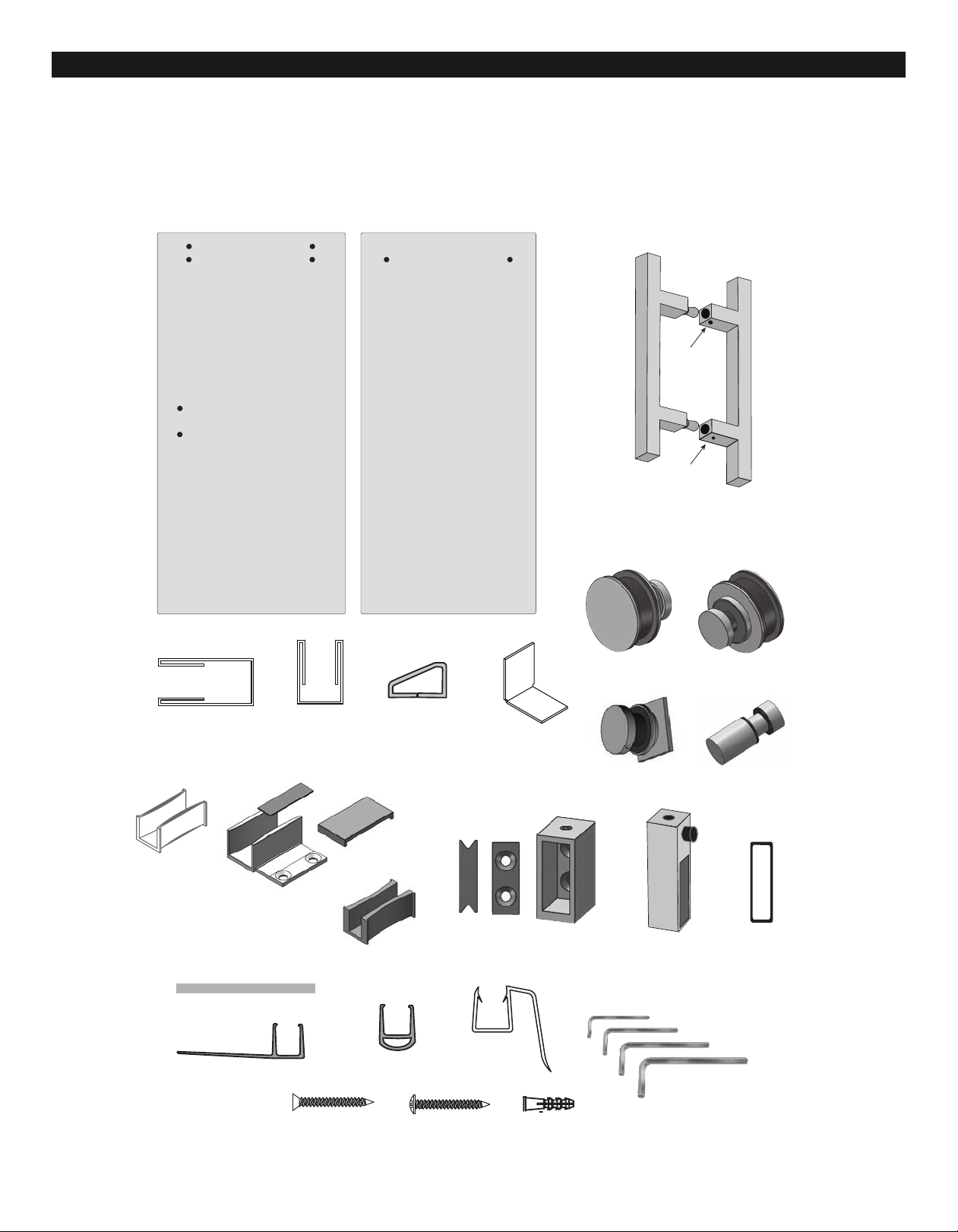
ITEM O. DESCRIPTIO QTY.
1 Vertical Wall Jamb ....................1
2 Fixed Glass Panel ....................1
3. Glass Door................................1
4. Door Handle Assembly .............1
6. Bottom “U” Channel..................1
7. Clear Setting Blocks .................3
8. Center Guide Assembly............1
9. Horizontal Rail .........................1
(with Panel Screw A embly ....
10. Horizontal Rail Mounting
Wall Brackets ..........................2
11. Plastic Guide Insert ..................1
12. Door Stop/Bumper....................2
13. Roller Assembly ........................2
14. Panel Screw Assembly .............2
(with Header ............................
15. Anti-Lift Standoff Assembly.......2
16. Clear “Bubble” Vinyl Bumper ....1
17. End Cap .................................1
18. Curb Dam .................................1
19. Clear “H” Vinyl .........................1
20. Plastic Wall Anchors.................12
21.Pan Head Screws, #8 x 1 1/4” ..7
22. Flat Head Screws, #8 x 1 1/4”..5
23. Hex Key Set (4)........................1
24. Splash Guard ...........................1
Parts Description
2
CAUTION: Risk of injury or product damage. Do not attempt to cut tempered glass.
IMPORTANT! Children should be supervised at all times while in Tub/Shower Enclosure.
IMPORTANT! Never use Door Handle or Towel Bar to support yourself. This is for towels or wash cloths only.
P EASE STOP THE INSTA ATION AND CONFIRM WITH FACTORY IF THE ACTUA NUMBER OR TYPE OF PARTS IS DIFFERENT
ASSEMB Y AND INSTA ATION
INSTRUCTIONS:
Gl sscr fters recommends the inst ll tion
be performed by tr ined inst ller.
• Read the manual and become familiar
with the steps involved in installation.
• This product requires Two persons for
safe installation.
• Always wear safety glasses during this in-
stallation.
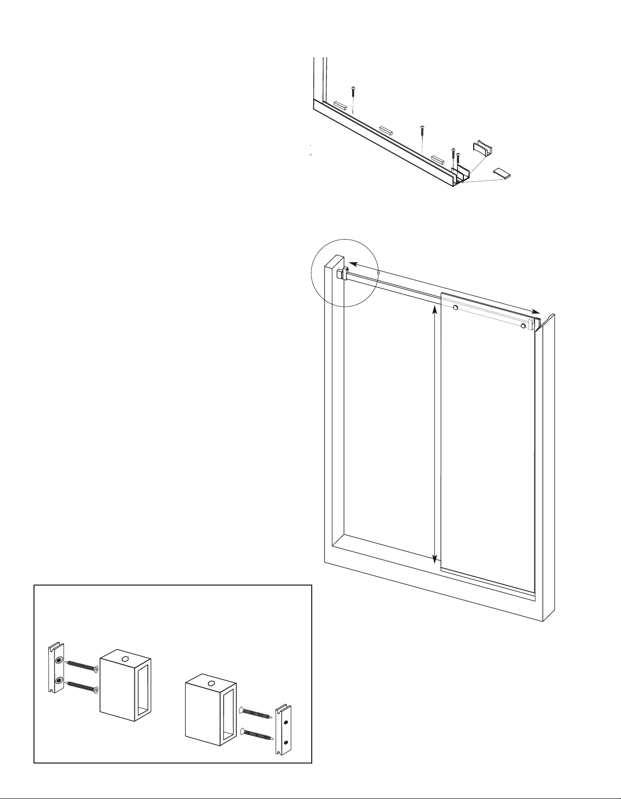
• The proper dimensions for this
installation were submitted at the time of
order. The Glass Panel and Door may
overlap to accommodate minor smaller
opening. One end of the Horizontal Rail
many be cut with a hacksaw for stainless
steel, but it must fit completely in the
Horizontal Rail ounting Brackets for a safe
installation.
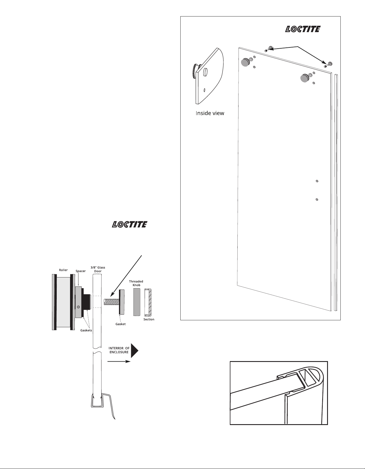
• When installing any mechanical parts
through the pre-drilled holes in the glass
door and panel be sure to use the gaskets
and bushings supplied between any metal
element and the glass. Do no over-tighten
any fittings.
• The glass used in this enclosure is
Tempered Safety Glass and features a
Tempered Safety Glass logo. Do not install if
Tempered Safety Glass logo is missing.
Call Customer Service.
• Tempered Safety glass cannot be cut,
ground, polished or manipulated in any
way.
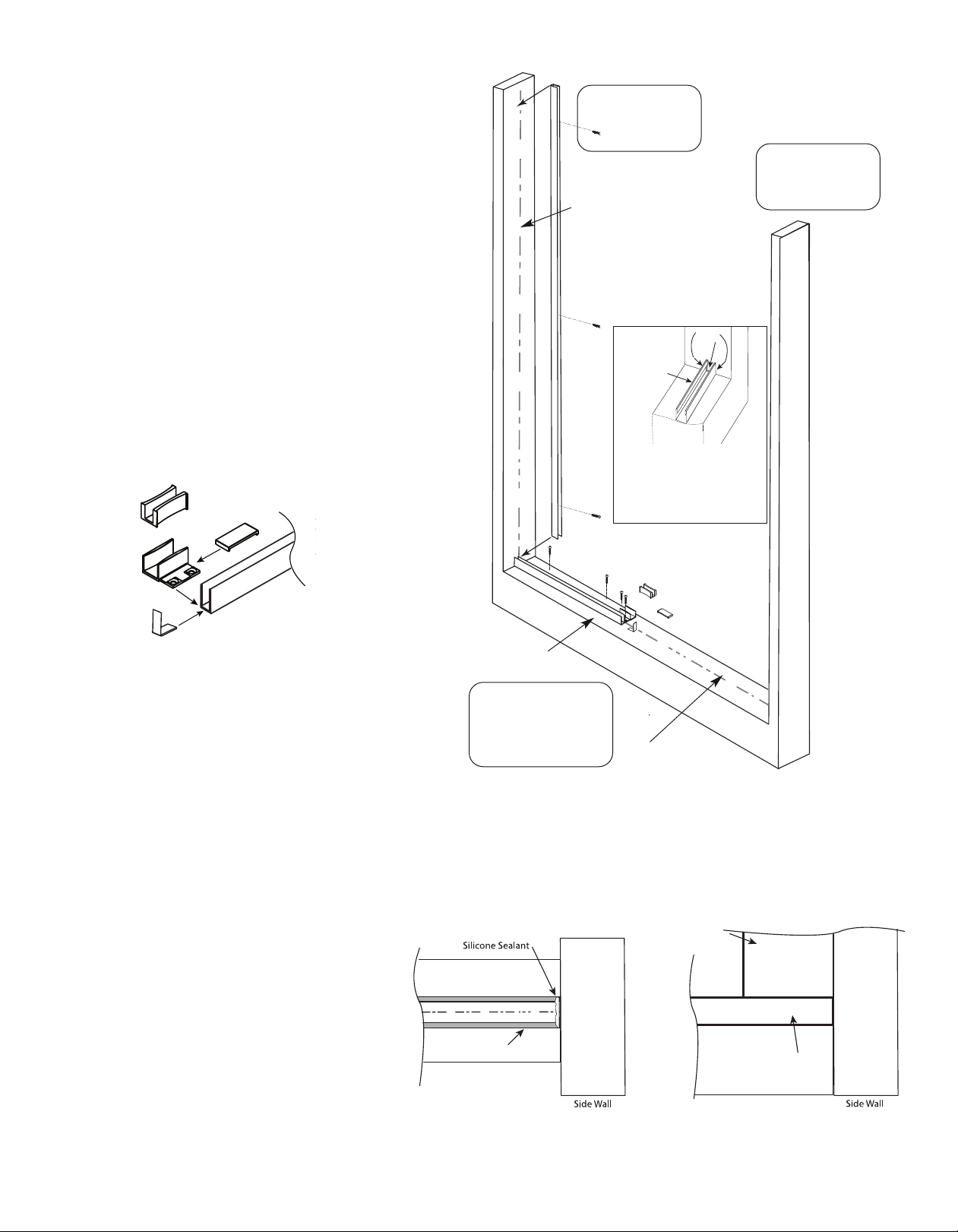
• If the installation is over ceramic tiles the
wall Jamb must lay flat on these tiles for the
entire height of the unit.
• Silicone Sealant is used to seal some parts
during installation and the inside of the
enclosure as shown in Detail #10. Do not
caulk from the outside of the enclosure.
Tools Required - For installation of Your Shower Enclosure
Safety glasses
Measuring tape
Pencil
Hacksaw or chop saw
(for stainless steel)
Miter Box or
Square
Level
Electric Drill/
Power Screwdriver
Center Punch
Rubber Mallet
Drill bit,
5/16” masonry
(for installation
on ceramic tiles
or marble)
#2 phillips
screwdriver
Caulking gun
Cutting Pliers
Suction Glass Lifters
(rated for more than 100 lbs)
WARNING: TO INSTALL ON CAST IRON, FIBERGLASS, ACRYLIC
OR RESIN TUB OR SHOWER BASE-
-
Check with the tub or shower base
manufacturer to determine the tooling required.
LOCTITE
243
BLUE
Loctite 243 Blue
Threadlocker
Medium strenght

3
Unpacking: • A box cutter should not be use to open any box.
• Please remove all staples from the box prior to unpacking metal and glass.
• Stand Panels upright on a cushioned base, such as a piece of carpet or towel.
• Do not remove corner protectors during staging of installation.
• Never place glass directly on hard surfaces.
• Any assembly that requires the panel to lay flat must be on a cushion surface.
Center Guide Assembly #8
Bottom
“U” Channel
#6
Horizontal Rail
#9
(Assembled with
Panel Screws #14)
Door
Stop/
Bumper
#12
Horizontal Rail
Mounting Bracket
Assembly
#10
Vertical
Wall Jamb #1
Door -- #3
Roller Limiter
#15
Roller Assembly #13
Fixed Panel #2
Curb Dam
End View
#18 End Cap
#17
Clear Vinyl
Door Bumper #16
Clear Setting Blocks #7
Clear
Plycarbonate
Splash Guard
#24
Clear “H” Vinyl #19
Plastic Wall Anchor
#20
Panhead #8 1 1/4”
#21
Flathead #8 1 1/4”
#22
2.5 mm
3 mm
4 mm
5 mm
HEX L KEYS #23
Panel Screws
#14
(Assembled on Header #9)
Locking
Set
Screws
Locking
Set
Screws
(Inner)
(Outer)
Handle Assembly #4
(view from bottom)
Guide 3/8” Glass
Plastic Insert #11
Note: the thinner Plastic
Insert is recommended for
use with the Splash Guard
(#24). See page 11.
Guide #8a
Alternate
Plastic Guide
#11d
Note: the alternate Plastic Guide is
is for use with 3/8” glas and no splash guard
Cover Plate #8b
Double Face
Tape #8c
IMPORTANT: Read all instructions carefully and become familiar with all parts before installation.

Align edge
Pencil Centerline
Roller adjustment
See page 13, Step 10
4
Inst ll tion Overview --
Showing steps for inst ll tion. Refer to p ges 6-15 for step-by-step inst ll tion descriptions.
6
4
4
5
3
1
2
1
8
7
9
A
10
6
A1
1e
11
1

5
Preliminary Steps: Inspect the complete product when
opening the box to ensure that all parts are accounted for,
intact and void of any damage from shipping.
STEP A -- Assemble the Door:
a) Stand the Glass door upright on a carpet or tarp
cushion to protect the glass. Position with the inside of the
door facing out. Have the second installer support the
door during installation of these parts.
b) Install the Clear Vinyl Bumper on the handle side of the
door. Use a rubber mallet to tap into place. Trim even with
the glass top and bottom. ( See Detail A1 below)
c) Install the Roller assembly in the top pre-drilled holes in
the door. The Roller is on the outside face of the glass with
the gaskets and plastic bushing between the metal parts
and the glass. The adjustment mechanism nut are in the
inside face. (See the Roller Assembly detail for parts
assembly). (Reserve final adjustment of the roller
assembly until after final installation of the door.)
d) Install the Bottom splash Guard on the door with the
flange facing to the inside. Trim even with the glass.
NOTE: Assembled door must be placed inside the shower
or tub before the fixed panel is finally installed.
(see step 6.
Detail Roller Assembly
Outside of Enclosure
Detail Door Assembly
Detail #A1
(Close-up view Clear Vinyl Bumper
on Glass Door)
OCTITE 243 Blue
Medium Strength
(not provided
with this unit)
OCTITE 243 Blue
Medium Strength
Apply Threadlocker glue
(Close-up view Bottom Splas Guard
on Glass Door)

6
WARNING: TO INSTALL ON A CAST IRON, FIBERGLASS,
GLASS TILE, ACRYLIC OR RESIN TUB OR SHOWER BASE
Check with the tub or shower base manufacturer to
determine the tooling required.
Detail 1C
Using the penciled centerline on the wall use a level to
recheck the exact vertical position. ark the top height
for the unit at 66” or 76”.
STEP 1. Determine the Plumb Condition of the
opening: Use a level to determined that the enclosure
is plumb on both sides.
Determine if your Tub/Shower Stall Enclosure curb
is evel and the Wall are plumb.
• 3/8” max. OOS (Out Of Square) for the Door Side;
• 5/8”max. OOS (Out Of Square) for the Panel Side;
• 3/8” max. OOS (Out Of Square) on the Bottom
(Base) of the enclosure.
If any side is out of plumb more than the above STOP
AND CALL CUSTO ER SERVICE.
Detail 1A
Use level to make
sure lines are plumb
Detail 1B
Draw a pencil lines: 1) front to back on the exact
center of the curb’ 2) left to right across the curb;
3) plumb vertical from the curb on the wall opposite
the spray head.
Find the idpoint of the
Curb and mark a pencil
line from front to back
Extend the
Centerline on
the curb and
mark a pencil
line on the verti-
cal wall for the
location of the
vertical Wall
Jamb.
76” high unit
66 high unit
ark for the finished
height of enclosure
Find the Centerline of
the curb and mark a
pencil line from left to
right.
STEP 1E . Measure and Cut the Header to size
Using the mark for the bottom of the bracket
measure the width of the opening for the header
location. Use a level to check the exact vertical
position for the width. Subtract 3/8” to 1/2” from
this width to allow for the brackets.
ark and cut the header. (Header
does not install until Step 6.)
• Use the mark for bottom of Wall Bracket.
• easure the width of the unit the level
height.
• Subtract 3/8” to 1/2” and mark this reduced
width on the header and cut the end of the
heade opposite the holes for the fixed panel
with a hacksaw.
NOTE: take care with the stainless steel
cladding on the Header that it does not
bend or scratch.
76”
66”
71 7
/8”
61 7
/8”
ark for bottom of
Wall Bracket 4 1/8”
below the mark for
the unit height
4 1/8”
Detail 1D
CUT ON Y DOOR SIDE OF THE HORIZONTA RAI , NOT THE PANE SIDE
Panel Screws
Trim Rail
This End Only
Horizontal Rail

STEP 2 -- Install the Bottom “U” Channel and Cen-
ter Guide:
a) Using the centerline on the base as a guide, place
the Bottom “U” Channel on the base on the outside of
the centerline. The end of the U Channel should touch
the wall marked for the wall channel l The plumb line
mark on the wall opposite the shower head will be the
guide for the wall channel.
b) Align the outside edge of the Center Guide to butt
against and align with the Bottom “U” Channel. ark
the locations for the screw holes in both predrilled
parts.
c) ove the parts aside and drill the holes. Use the
proper bit for the enclosure materials
d) Put a small amount of silicone sealant in each hole,
insert the plastic wall anchor. Clean the top of the base
of all debris. Put a thick, continuous bead of Silicone
Sealant on the underside of the Bottom “U” Channel
and the Center Guide. Also apply a bead of silicone
sealant to of the end of the Bottom “U” Channel on the
wall side before it is installed.
(Detail #2d). Screw both parts into place with the
#8 1 1/4” flat head screws (#22).
e) To complete the
installation of the
Center Guide apply
the double face
tape supplied to
the areas around
the screw holds,
remove the tapes
second side cover-
ing and press the cover plate into place. Be sure that
the thin plastic insert (#11) for the glass is inside the
Center Guide.
STEP 3 -- Install the Vertical Wall Jamb for the Fixed
Panel:
a) Position the Vertical Wall Jamb on top of the Bottom
“U” Channel as installed. It must align to th outside of
the marked plumb line and be directly over the Bottom
“U” Channel. (Detail #3). Recheck for level and plumb.
b) ark the position for the pre-drilled holes in the
level and plumb Vertical Wall Jamb. Set jamb
aside and drill using proper bit for the
enclosure
materials. Clean the surface of debris, add a
small amount of silicone sealant in each hole
and then insert the plastic wall anchors.
c) Place the Vertical Wall Jamb on the Bottom
“U” Channel aligned directly over the Bottom
“U”
Channel.Screw into place with three #8 1 1/4”
panhead screws (#21).
(NOTE: complete sealing of the inside of the unit will be
done as the final step). 7
Bottom”U” Channel Bottom
”U” Channel
Top View of Bottom“U” Channel (Step 2d) Side View of Vertical Wall Channel (Step 3a)
Base
Base
Vertical
Wall Channel
DETAI #3DETAI #2d
DETAI #2
Panel Side
Max. 5/8”
Ou -of-Square
Bo om Opening
(Lef o Righ )
Max. 3/8”
Ou -of-Square
Door Side
Max. 3/8”
Ou -of-Square
Centerline
Plumb Line
CURB
Bottom
“U” Channel
Silione
Sealant
DETAI #2d
Put Silicone Sealant on
the under ide of the
Bottom “U” Channel
and where the
Bottom “U” Channel
meet the wall
Align
Center Guide
Thin Plastic Insert
End Cap
Cover Plate
U Channel

STEP 4 -- Assemble the Horizontal Rail on the Fixed
Panel for position:
a) The Panel Screws are shipped in position on the
Horizontal Rail. Unscrew to assemble the Horizontal
Rail on inside of the fixed glass panel.
(See Details 4a & 4b).
Attach the Horizontal Rail to the Fixed Panel on the
inside face using the two Panel Screw Assembly sets
supplied pre-installed on the Horizontal Rail. ( See detail
#4) Be sure the assembly is secure and tighten the set
screw on the Panel Screws with the Allen Wrench
supplied.
Next, slide both Door Stop/Bumpers on the Horizontal
Rail, one at each end of the Horizontal Rail with the
rubber bumper facing to the middle. Temporarily
tighten to hold in place. Then slide the Horizontal Rail
ounting Wall Brackets fully on both ends of the
Horizontal Rail and tighten into place. Test fit the
assembly next to the bottom U Channel and in the Wall
Channel. It should fit in the opening with not more than
3/16” space at either end to allow for adjustment within
the wall bracket. ove outside the unit and stand the
glass on a carpet or padding to protect the glass.
8
DETAI #4c -- Assemble The Header for test fit
DETAI #4d -- Test Fit the Header and Fixed panel
DETAI #4a-- Horizontal Rail
installed on the Fixed Panel
(As viewed from t e inside)
Panel Screws Door Bumper
Door Bumper
Rail Mounting
Wall Brackets
Rail Mounting
Wall Brackets
Horizontal Rail
Detail 4b -- Test Fit of Assembled Horizontal Rail
3/16” space to allow for adjustment

STEP 5 -- Set the Fixed Panel for position:
Place the clear Setting Blocks in the Bottom “U”
Channel, evenly space about 2” from each end. Do not
place on top of any of the screw heads. Two persons
should be used to lift the assembled Fixed Panel to fit
the panel in the Threshold and slide the panel into the
Vertical Wall Jamb.
STEP 6 -- Installation of the Horizontal Rail Wall
Mounting Brackets:
Check for level and Plumb position.
a) Using a pencil, mark the outline of both the left and
right Horizontal Rail ounting Wall Brackets.-
b) Remove the assembled Fixed Panel with the
Horizontal Rail and lean against a wall outside of the
enclosure. Stand the glass on a carpet or padding to
protect the glass.
c) Loosed the set screw on the top and remove the
ounting Brackets from the Horizontal Rail. Place the
ounting Brackets in the outlines as marked on the
wall and mark for the screw locations. Drill the holes.
Use the proper bit for the enclosure
materials. Place a small amount of silicone sealant in
the holes and inset the plastic anchors. Screw the inner
Wall Brackets into place using the #8 1 1/4” flat head
screws (#22).
d) Assemble the Rollers on the Door. (The Anti- Lift
Standoffs are installed after the Door is installed on the
Rail.)
e) VERY IMPORTANT— MOVE THE ASSEMB ED DOOR
into the enclosure with the Rollers facing to the
outside of the shower. Place the glass door on a rug
or padding to protect the glass. (The side with the
holes for the Handle should be on the side opposite
the Fixed Glass Panel.)
f) Return the outer ounting Brackets to each end of
the Horizontal Rail. Replace the Fixed Panel in position
in the Vertical Wall Jamb and Bottom “U” Channel. Slide
the outer part of both Horizontal Rail ounting
Brackets flush to the wall over the inner portion as
mounted in the wall. Re-check for level and plumb and
fix into place with the set screws and Allen Wrench
provided.
9
DETAI #6a -- Mark the positions for the
Horizontal Rail Mounting Wall Brackets
DETAI #6b -- Inner portion of Horizontal Rail
Wall Mounting Bracket as affixed to the wall in the
marked positions.
DETAI #5a -- Clear Setting Blocks
Check For evel
Check For Plumb

10
STEP 7 -- Install the Door from the Inside of the Unit:
Two persons should be used to lift the Door onto the
Horizontal Rail. The bottom of the door goes in the Plastic
Insert in the Center Guide. Install the Anti-Lift Standoff
Assemblies in the pre-drilled holes in the door below the
Horizontal Rail. The Anti-Lift Standoff threaded knob
inserts from the inside. Be sure to use the gaskets
between the knobs and the glass as well as the plastic
bushing within the hole to protect the glass. Screw the
Anti-Lift Standoff Assemblies in place hand tight.
(Final installation with the set screw is completed in Step
#10 after the roller adjustment procedure.)
7b) ove the door to the closed position and then relocate
the Door Stop/Bumper to the proper location against the
roller when the clear vinyl bumper makes contact with the
wall.
7c) ove the door to the fully open position and relocate
and set the Door Stop/Bumper to prevent the door handle
from hitting the panel and/or to prevent the door glass
from hitting the wall.
DETAI #7a
DETAI #7
(As viewed from t e outside)
DETAI #7b
(Panel wit fittings as viewed from t e side)
Anti-Lift Standoff is installed on
t e Door under t e Horizontal Rail
to prevent unmounting of t e door.
Do Not tig ten in place until after
t e roller adjustment in Step #10.)
Using t e set screw at t e bottom
fix t e Door Stop/Bumper in
position

DETAIL #8b
Double Face Tape
Fixed Glass Pan
Glass Door
Center Guide Bottom Cover Curb Dam
End Cap
Wall Channel
Plastic Insert
DETAIL #8c— Section view
Inside of the unit
Inside of the unit
Fixed Glass Pan
Glass Door
Center Guide
End Cap
Wall Channel
Thin Plastic Insert
Splash Guard
Bottom Cover Curb Dam
STEP 8 -- Install the End Cap and the Curb Dam:
a) To Install the End Cap first put a bead of Silicon Sealant inside the
base of the end of the U Channel. Add sealant to the inside face of
the vertical part of the End Cap. Slide the End Cap into the U Channel
and press firmly into place.
b) Place the Curb Dam into position in front of the U channel to
butting the wall. ark the Curb Dam to fit and cut to size with a stain-
less steel hacksaw. Test fit and mark the curb end position on the
wall,
parallel with the centerline. Place a small amount of silicone sealant
on each end. Wipe the base clean of all debris. Clean surface with de-
natured alcohol. (Do Not remove the pencil marks for the outside of
the Curb Dam.)
The Curb Dam comes with Double Face Tape on the bottom, peel
away the paper covering place in position to your marks and press
into place as aligned with the marks and the End Cap.
11
DETAIL #8d— Special Installation
without the Splash Gua d
DETAI #8c— Section view showing the
recommended upgrade with the Installation
of the Splash Guard as shown in Step 1.
DETAI #8a
If you have chosen not to install the upg ade in Step 1 and
now find that the e is excessive splashing o leaks a Splash
Gua d is supplied fo the doo bottom. To install this pa t:
a) emove the doo ; b) cut to size and install the Splash Gua d
on the bottom of the glass; c) switch the plastic inse t in the
Cente Guide fo the one supplied with thinne walls;
d) einstall the Doo .
Inside of the unit
Outside
of the unit
Recommended upgrade—replace the pla tic in-
ert with the thinner in ert when u ing the
optional Poly Bottom Spla h Guard
(See Detail 12D)

12
DETAI #9
(As viewed from
t e inside)
DETAI #9b Clear “H” Vinyl
(As viewed from t e inside)
DETAI #9a
(As viewed from
t e inside)
STEP 9 -- Install the Clear “H” vinyl:
To install the “H” Clear Vinyl on the Door from the inside.
Begin at the bottom edge with the flange pointing to the
space between the Door and the Fixed Panel. Press or tap
into place with a Rubber allet. Trim with cutting pliers to
fit just below the Horizontal Rail.

13
STEP 10 -- Adjust Roller Height:
Remove the Threaded Knob covering the Roller
mechanism on the inside of the unit. Using the 2mm Hex
Wrench in the Hex Slot position on either side of the
Spacer hold the assembly in position while loosening the
locking nut as shown below with the 4mm Hex Wrench.
DETAI #10
Using the 2mm Hex wrench turn the Roller on the Axel to
lift and adjust the door for level. Hold in place and tighten
the Locking Nut.
Remove the Hex Wrenchs and replace the Threaded Knob.
(Do Not Over-tighten the Locking Nut or the Threaded
Knob.)
Remove Knob
Cover during
adjustments

STEP 11 -- Install the Handle:
Insert the inside portion of the Handle (the part with the
tapered knob) through the glass into the outer handle.
Use vinyl gaskets and bushings to protect the glass. Us
the proper Hex “L” wrench to tighten the set screws in
the outer Handle to fix the Handle to the Door.
14
DETAI 11 -- Installing the Handle
(As viewed from t e inside)
Inside Enclosure
Outside Enclosure
DETAI 11b
(Handle Shown from Below.
The set Screw is on the outside.)

STEP12 -- Seal from the inside with Silicone:
Apply Silicone Sealant along the inside face of the Vertical Wall Jamb, Bottom “U” Channel, Curb Dam and the seam
between the Cover Plate and the U Channel as per the drawing and details #12.
(No sealant is required on the Center Guide.)
et cure for 24 hours before use.
End Cap
Plastic Insert
Splash Guard
DETAI #12a --
Sealing the Wall Jamb and Curb Dam
DETAI #12 -- Caulking Top view
15
Silicone Sealant is shown here as applied
to the INSIDE of the unit.

Revised 4/2019
GLASSCRAFTERS, INC
193 eterans Blvd., Carlstadt, NJ 07072
1+(888) 683-1362 (F) (201) 525-1117
Cle ning Recommend tions:
Never use br sive cle ners or cle ners
cont ining mmoni . This m y c use
chemic l d m ge .
For cleanin , we recommend usin ammonia free
Sprayway brand lass cleaner, which is available
at a variety of retail outlets.
www.spraywayinc.com/content/ lass-cleaner
16
C EANING INSTRUCTIONS:
Never use scouring powder, pads or sharp instruments
on metal work or glass panels. We recommends the use
of a squeegee after each shower to eliminate water
spots on the inside of the glass panels. An occasional
wiping down on the glass panels an metal parts with a
mild detergent, diluted in water, is all that is need to
keep your Shower/Tub enclosure looking brand new.
Acero Series Models
Catalog Number PSS- Polished Stainless Steel
BSS Brushed Stainless Steel
IBK Iron Black
ORB Oil Rubbed Bronze
Shower Enclosures
etal Finish
AS-60T-38 PSS
AS-60T-38 BSS
AS-60T-38 IBK
AS-60T-38 ORB
AS-54T-38 PSS
AS-54T-38 BSS
AS-54T-38 IBK
AS-54T-38 ORB
AS-48T-38 PSS
AS-48T-38 BSS
AS-48T-38 IBK
AS-48T-38 ORB
Tub Enclosures
etal Finish
AT-66T-38 PSS
AT-66T-38 BSS
AT-66T-38 IBK
AT-66T-38 ORB
AT-60T-38 PSS
AT-60T-38 BSS
AT-60T-38 IBK
AT-60T-38 ORB
NOTES:
Model Number… ___________________________________
Dealer ________________________________________________
Job og # _____________________________________________
This manual suits for next models
5
Table of contents
Other GlassCrafters Other manuals
Popular Other manuals by other brands

Aodyo Instruments
Aodyo Instruments Sylphyo Link user guide

F-SECURE
F-SECURE MOBILE SECURITY - QUICK GUIDE FOR BUSINESS Getting started

Nedap
Nedap COMBI-BOOSTER installation guide

hopf
hopf 8029NTS-V2/GPS Technical manual

Iron-Fence Shop
Iron-Fence Shop STRONGHOLD IRON installation guide

Basement Systems
Basement Systems Sani Dry CSB Installer's & owner's manual