Glidecam X-10 Setup guide

Set-up and Operations Guide
Glidecam Industries, Inc. 23 Joseph Street, Kingston, MA 02364
Customer Service Line 1-781-585-7900
Manufactured in the U.S.A.
COPYRIGHT 2013 GLIDECAM INDUSTRIES,Inc. ALL RIGHTS RESERVED
MANUAL

TABLE OF CONTENTS
SECTION # PAGE #
1. Introduction 3
2. Quick Setup 4
3. Adjusting The Load Settings Of Your Support Arm 13
4. Removing The Springs From Your Support Arm 17
5. Installing The Springs Into Your Support Arm 21
6. Professional usage 25
7. Maintenance 25
8. Safety Precautions 25
9. Warnings 25
10. Warranty 26
2

Congratulations on your purchase of a Glidecam X-10 Camera Stabilization System.
In order to use the X-10 system, it is best to have a basic understanding of how the
system works in advance. So please make sure you read this section before trying
to setup and operate the X-10 Camera Stabilization System.
The X-10 Camera Stabilization System is designed to allow you to walk, run, go
up and down stairs, shoot from moving vehicles and travel over uneven terrain
without any camera instability or shake, when used with the GLIDECAM XR-
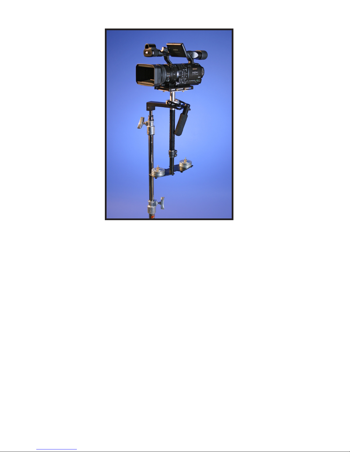
SERIES or GLIDECAM HD-SERIES (not included). The GLIDECAM XR-SERIES
and GLIDECAM HD-SERIES are generally used as hand-held camera stabilizers;
however, they can also be used with the X-10, and when they are, they are referred
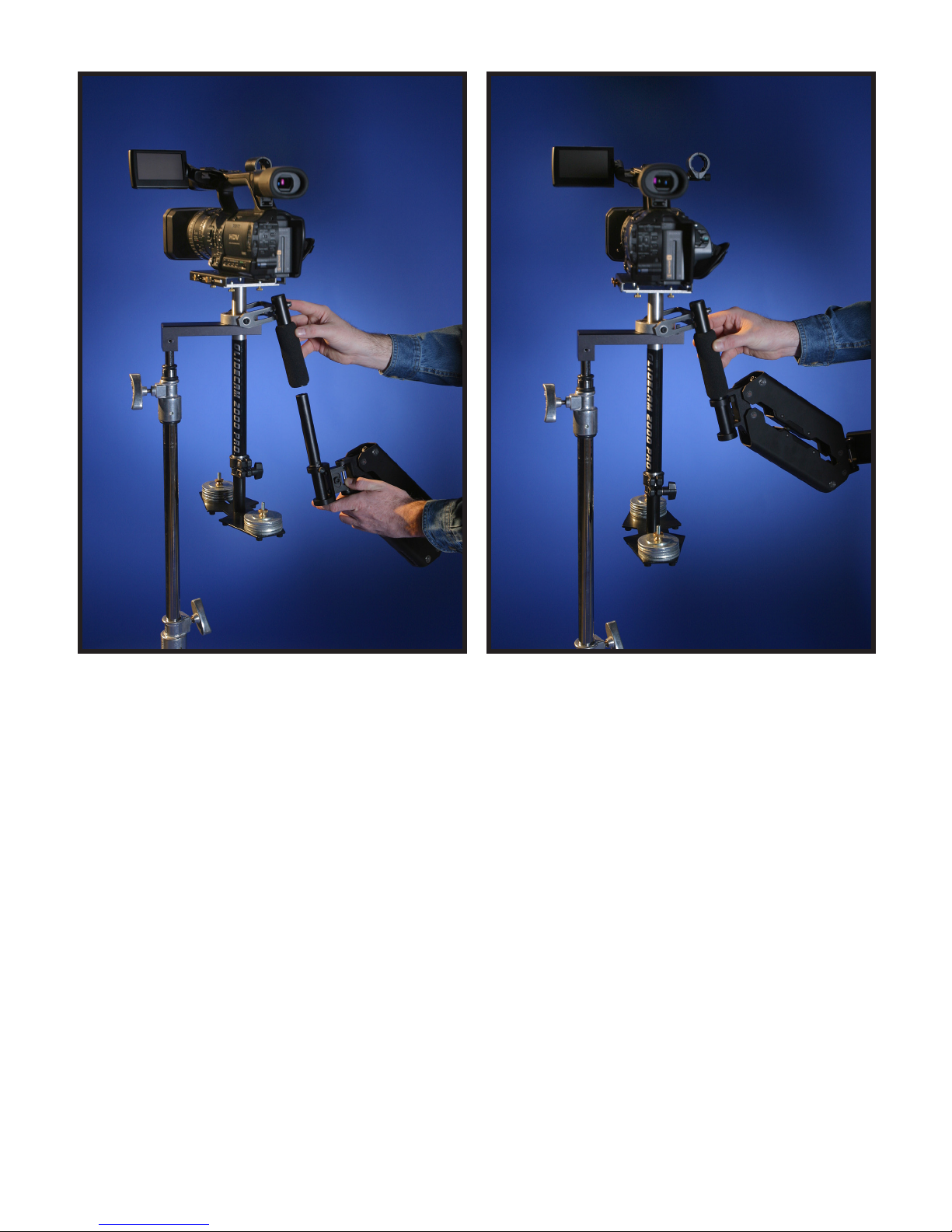
to as a SLED. The SLED carries your camera and is attached to the end of the
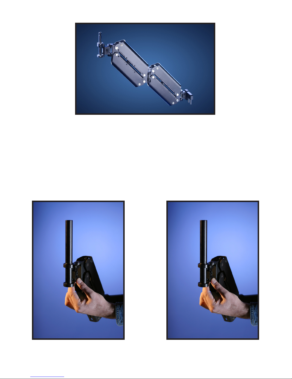
SPRING-LOADED SUPPORT ARM, which, in turn, is attached to the GLIDECAM
SUPPORT VEST.
When using the GLIDECAM XR-SERIES or GLIDECAM HD-SERIES in hand-held
mode, your arm is carrying the weight of the SLED. However, when the XR-SERIES
or HD-SERIES are used with the X-10, it is the X-10’S SPRING-LOADED SUPPORT
ARM that carries the weight of the SLED. Because of this, you will now be able to
shoot for extended periods of time, whereas before, the stress associated with hand
holding the SLED reduced your shooting time.
While the X-10 is in essence a very simple device, its simplicity doesn’t lend ease in
answering that often asked question, “how does it work?” To answer this question
completely would require delving into Newtonian Physics and Classical Mechanics.
We would have to explain - center of gravity displacement, inertia, reduced friction
and angular motion reduction etc. However, a quick answer reveals the X-10 works
by “isolating” your body’s motion from your camera, while your camera is balanced in
an isolated and relatively motionless state.
The X-10 requires practice and understanding to achieve professional looking results.
We highly recommend that the user read this manual thoroughly before setting up
and operating the X-10. Doing so will save you time, and will minimize the risk of
damage to your camera or the X-10. It is important to perform and follow the Setup
and Operation’s procedures in the proper sequence, so as to avoid both frustration
and a possible accident.
If you need technical assistance, you can page our Technical Support Line at 1-508-
830-1414, between the hours of 10:00 AM and 5:00 PM, Eastern Standard Time,
Monday through Friday. We’re sure that once you have your X-10 up and running,
you will nd years of enjoyment with it.
#1 INTRODUCTION
3

4
#2 QUICK SETUP
Since you will be using your X-10 with either a GLIDECAM HD-SERIES or GLIDECAM XR-SERIES
(hereafter referred to as the SLED), you should make sure that your SLED is already setup and
properly balanced. Please see the GLIDECAM HD-SERIES or GLIDECAM XR-SERIES Manual
for details regarding proper SLED setup and balancing procedures.
Figure 2Figure 1
Included is a X-10 HD DOCKING BRACKET, which allows you to park your SLED while it is not
in use. Securely attach and tighten the DOCKING BRACKET onto the 5/8” RECEIVING PIN of
an INDUSTRY-STANDARD C-STAND (Not Included) as in gures 1 and 2.
It is always best to park your SLED on the provided HD DOCKING BRACKET, as in gure 3.
However, if you do not currently have a C-STAND, it is acceptable to park your SLED on a TABLE
TOP and therefore not use the DOCKING BRACKET.

5
Figure 3
When you park your SLED onto the HD DOCKING BRACKET, make sure that the SLED’S
HANDLE is facing directly outwards as in gure 3. By parking your SLED this way on the HD
DOCKING BRACKET, it will be easily accessible to you when it comes time to put the SLED onto
the end of the SUPPORT ARM.

6
Figure 4
The X-10’S SUPPORT ARM (gure 4) comes congured with two EXTENSION SPRINGS, which
are already installed. These SPRINGS are also preset to their weakest LOAD SETTING. Later,
in the CONFIGURATION SECTION, we will discuss how to make adjustments to the arm in detail.
For now, leave the SPRINGS in the SUPPORT ARM at their factory setting.
Now, install the BLACK ARM POST into the ARM POST CLAMP at the end of the SUPPORT
ARM, as in gures 5 and 6.
Figure 6Figure 5

7
Figure 7
Tighten the ARM POST into the ARM POST CLAMP, making sure to align the NOTCHES in the
ARM POST so that they face the TIGHTENING SCREW as shown in gure 7. Do not OVER
TIGHTEN this PLASTIC TIGHTENING SCREW, for this could damage the THREADS. The reason
that the TIGHTENING SCREW is made of plastic is so that it will not scratch the ARM POST.

8
Put the GLIDECAM SUPPORT VEST on next. Adjust the STRAPS on the VEST until the VEST
ts you comfortably; however, make sure that the VEST is not on too loosely, for it needs to bear
the combined weight of the SUPPORT ARM and SLED. Also, you should take note that if you
are planning on walking up and down stairs or walking over uneven terrain, that you should make
sure that the very bottom of the vest is not positioned so low on your torso that it inhibits your legs
from moving up and down fully.
Figure 9Figure 8
Figure 10

9
Connect the X-10 SUPPORT ARM to the GLIDECAM SUPPORT VEST. First, note the location of
the two RECEIVING HOLES in the ARM CONNECTOR BAR shown in gure 10. Next, carefully
align and guide the two STEEL PINS located on the back end of the RIGID ARM down into the two
RECEIVING HOLES as in gure 11. Make sure that the arm is fully inserted into the RECEIVING
HOLES as in gure 12.
Figure 11 Figure 12
Figure 13
If everything has been done properly so far, you should now have the SUPPORT ARM attached
to the VEST, as in gure 13.
CHANGE TO LEFT HAND OPERATION
If you choose to change the Glidecam X-10 Arm from the factory set right hand operation to left
hand operation, you will need to follow the instructions in your operator vest section and then you
will need to remove the 4 screws that attach the 2-pin block to the pre-arm and then rotate the
2-pin block 180 degrees, then reinstall the screws from the opposite side. Now you can push the
2-pin block into the vest block on the bridge plate and you are set up for left handed operation.

10
Figure 14 Figure 15
You can now attach the SUPPORT ARM to the SLED by carefully aligning and guiding the ARM
POST all the way into the bottom of the SLED HANDLE as in gures 14 and 15. After you have
done this, hold onto the SLED HANDLE rmly so that as you carefully lift the SLED straight up
and out of the DOCKING BRACKET, you can make sure that the weight of the SLED is in the
control of your ARM and not the SPRING-LOADED SUPPORT ARM. Now gradually let the
SUPPORT ARM take over the job of holding the weight of the SLED. If your SLED is too heavy
for the SUPPORT ARM at its current LOAD SETTING, the weight of the SLED will angle the
SUPPORT ARM downwards. If your SLED is too light for the SUPPORT ARM at its current LOAD
SETTING, the SLED will angle the SUPPORT ARM upwards.
If your SLED is the correct weight for the SUPPORT ARM at its current LOAD SETTING, the ARM
will remain level as in gure 16.

11
Figure 16
If your SLED is too heavy for the SUPPORT ARM, in the ARM’S current factory setting, you will
need to increase the SPRING TENSION of the ARM by following the procedures outlined in the
ADJUSTING THE LOAD SETTINGS OF YOUR SUPPORT ARM section of this manual.
If your SLED is too light for the SUPPORT ARM, in the ARM’S current factory setting, you will
need to decrease the LOAD CAPACITY of the ARM by removing one of the SPRINGS as outlined
in the REMOVING THE SPRINGS FROM YOUR SUPPORT ARM section of this manual.

12
Figure 17
The X-10 is designed to work best when the system is operated with the SLED positioned directly
in front of you, as in gures 17 and 18. This position allows you a clear view of either the LCD
MONITOR on your camcorder or the LCD MONITOR on the BASE PLATFORM of your SLED.
NOTE: This picture actually show the GLIDECAM SMOOTH SHOOTER; however, the GLIDECAM X-10 should
be positioned in the same way.
Figure 18
Also, you should note that when using the SLED in HAND-HELD mode, you were instructed to
rmly hold onto the HANDLE. This was due to the fact that you had to support the entire weight
of the system in your hand. However, now that the X-10 SUPPORT ARM is holding the weight of
the system, holding the HANDLE gently, as in gure 18, yields superior results.
NOTE: This picture actually show the GLIDECAM SMOOTH SHOOTER; however, the GLIDECAM X-10 should
be positioned in the same way.

13
#3 ADJUSTING THE LOAD SETTINGS OF
YOUR SUPPORT ARM
In order to change the LOAD SETTING of the SUPPORT ARM, you will need to either change the
SPRING TENSION within the ARM, or add or remove a SPRING from the ARM. Both of these
changes can be made using the supplied ALLEN WRENCHES (not included).
When you receive your X-10, it comes congured with both SPRINGS already installed and set
to their weakest SPRING TENSION setting.
In order to adjust the SPRING TENSION in the SUPPORT ARM, you must rst make sure that
the SLED is not on the end of the ARM and that the ARM is not attached to the VEST. You must
also make sure that the ARM is not under load and that it is angled upwards.
Figure 19
To increase or decrease the SPRING TENSION within the ARM, you will need to either lengthen
or shorten the SPRING with an ALLEN WRENCH as shown in gures 19 and 20.
NOTE: This picture actually show the GLIDECAM SMOOTH SHOOTER; however, the GLIDECAM X-10 should
be setup in the same way.

Figure 20
14
Figure 21
NOTE: Figures 20 and 21 show the GLIDECAM SMOOTH SHOOTER; however, the GLIDECAM X-10 should
be setup in the same way.

15
When you change the length of the SPRINGS, you will be able to see their positions change in
the GUIDE SCALE WINDOWS located on the top and bottom of the SUPPORT ARM (gure 21).
The MARKINGS next to the GUIDE SCALE WINDOWS indicate the different LOAD SETTINGS.
You can set the SPRINGS from 0 to 6 and anywhere in between, with 0 being the weakest, and
6 being the strongest.
If your SLED is too heavy for the SUPPORTARM, you will need to increase the SPRING TENSION
of the ARM. If your SLED is too light for the SUPPORT ARM, you will need to decrease the
SPRING TENSION of the ARM. Additionally, you may need to either add or remove a SPRING
from the SUPPORT ARM to either increase or decrease the ARM’S load-carrying capacity. Your
goal in making these adjustments is to support the weight of the SLED while the ARM remains
level, as shown in gure 16.
When you use the SUPPORT ARM with only one SPRING in it, it can hold a maximum load of
9 pounds at its strongest setting. When you use the SUPPORT ARM with two SPRINGS in it, it
can hold a maximum load of 18 pounds at its strongest setting. It should be pointed out that the
maximum loads above refer to the weight of your CAMERA and SLED combined, and not just the
weight of your CAMERA alone.
NOTE: The X-10 SUPPORT ARM is optimized to take advantage of the principle that the more inert a camera system
is, the more stable it is. In other words, the heavier your camera or combined camera and SLED are, the more stable
your resulting footage will be. So therefore you should always try to use the X-10 SUPPORT ARM at its maximum
LOAD CAPACITY for a given SPRING combination. In practice, this optimization will occur when a 9-pound SLED
is used with only one SPRING installed in the arm, or when an 18-pound SLED is used with two SPRINGS installed
in the arm.
We have provided STEEL WEIGHT PLATES (not shown) with the X-10 so that you may use them
to increase the total weight of your SLED. This is so that the combined weight of your CAMERA
and SLED can equal approximately 9 pounds when used with one SPRING in the ARM, or 18
pounds when used with two SPRINGS in the ARM.
In addition to the STEEL WEIGHT PLATES, we have also provided one black, lightweight ARM
POST. Shown in gure 22.

Figure 22
16

17
#4 REMOVING THE SPRING FROM YOUR
SUPPORT ARM
Figure 23
In general, when using a GLIDECAM HD-2000, you will achieve superior stabilization with only
one SPRING installed in the SUPPORT ARM. When using a GLIDECAM HD-4000, you will
achieve superior stabilization with two SPRINGS installed in the SUPPORT ARM.
Figure 24

18
Figure 25
In order to remove or install either of the SPRINGS in the SUPPORT ARM, you must rst make
sure that the SLED is not on the end of the ARM and that the ARM is not attached to the VEST.
You must also make sure that the ARM is not under load and that it is angled upwards. With
the ARM angled upwards, you can easily remove the ADJUSTER BOLT or BOLTS as shown in
gures 23-25.
With both ADJUSTER BOLTS removed, you can now angle the SUPPORT ARM downwards,
thereby allowing you easy access to each SPRING’S RETAINING BOLT as in gure 26.
NOTE: You will not be able to angle the SUPPORT ARM downwards if one of the ADJUSTER BOLTS remains
attached to the SPRING. Both ADJUSTER BOLTS must be removed for the ARM to be angled downwards.

19
Figure 26
Figure 27
With the ARM angled downwards, you can now easily remove the RETAINING BOLT or BOLTS
as shown in gures 26 and 27.

20
Figure 28
Now that the ADJUSTER BOLTS and RETAINING BOLTS are disconnected from each end of the
SPRING, you will be able to slide the SPRING out of the SUPPORT ARM as shown in gure 28.
Table of contents
Other Glidecam Camera Accessories manuals
Popular Camera Accessories manuals by other brands

Sony
Sony Cyber-shot Station CSS-PC1 user guide

NEC
NEC VERSABAY IV 6-CELL SECONDARY BATTERY manual

Moog Videolarm
Moog Videolarm POD7CW Installation instructions manual

Nikon
Nikon AF Nikkor 50mm f/1.8D user manual

Lithion
Lithion Valence U-CHARGE XP Series Quick reference guide

Voltacon
Voltacon Li-2021 48100R user manual