Glidecam XR-1000 User manual

Set-up and Operations Guide
Glidecam Industries, Inc. 23 Joseph Street, Kingston, MA 02364
Customer Service Line 1-781-585-7900
Manufactured in the U.S.A.
COPYRIGHT 2015 GLIDECAM INDUSTRIES,Inc. ALL RIGHTS RESERVED
MANUAL
GLIDECAM
XR-SERIES
XR-1000 / XR-2000 / XR-4000

2
TABLE OF CONTENTS
SECTION # PAGE #
1. Introduction 3
2. Glidecam XR-Series Parts And Components 4
3. Assembling Your Glidecam XR-Series 8
4. Attaching Your Camera To Your Glidecam XR-Series 15
5. Balancing Your Glidecam XR-Series 18
6. Handling Your Glidecam XR-Series 23
7. Operating Your Glidecam XR-Series 24
8. Shooting Tips 26
9. Improper Techniques 27
10. Other Camera Attachment Methods 28
11. Professional Usage 28
12. Maintenance 28
13. Warning 29
14. Warranty 29
15. Online Information 30

Congratulations on your purchase of a Glidecam XR-1000, XR-2000 or XR-4000.
The Glidecam XR-SERIES is a lightweight, aluminum, hand-held camcorder
stabilizing system designed to allow you to walk, run, go up and down stairs and travel
over rugged terrain without any camera instability or shake. When used correctly
the Glidecam XR-SERIES can move with such uidity and grace as to be virtually
indistinguishable from shots made by professional dollies, cranes and stabilizers.
The Glidecam XR-SERIES is the most versatile and dynamic of all the consumer
camcorder stabilizers on the market. It can shoot straight up and down, or even
sideways and still produce stable images.
Fluid tilts and pans, crane-like booms, dolly-type maneuvers, and the ability to shoot
smooth shots from moving vehicles are all easily accomplished with the Glidecam
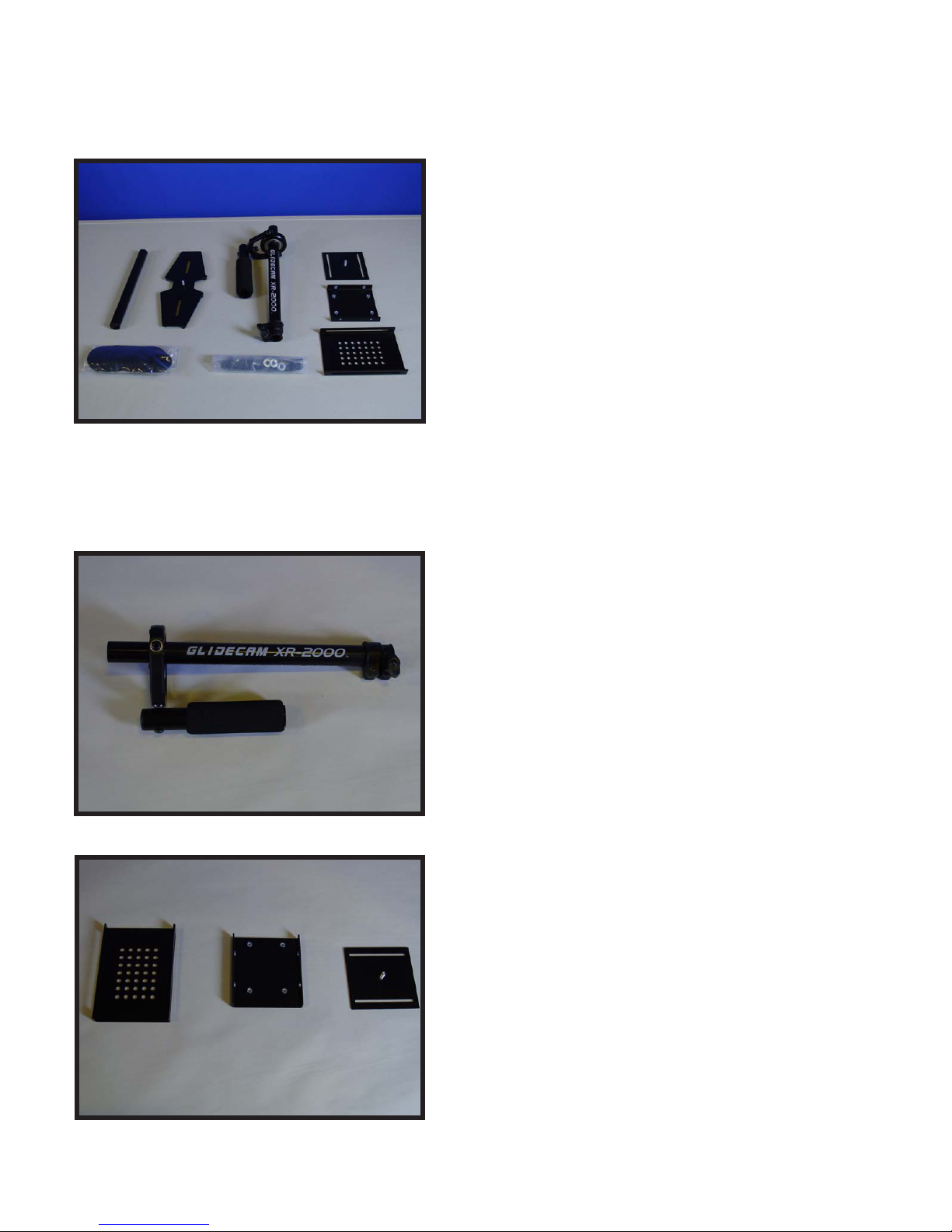
XR-SERIES. The offset gimbaled handle-grip and enclosed bearing assembly allow
your hand to move freely in several directions, while the horizontal yoke allows your
hand and arm to move up and down, alleviating the bouncing, pogo-type action
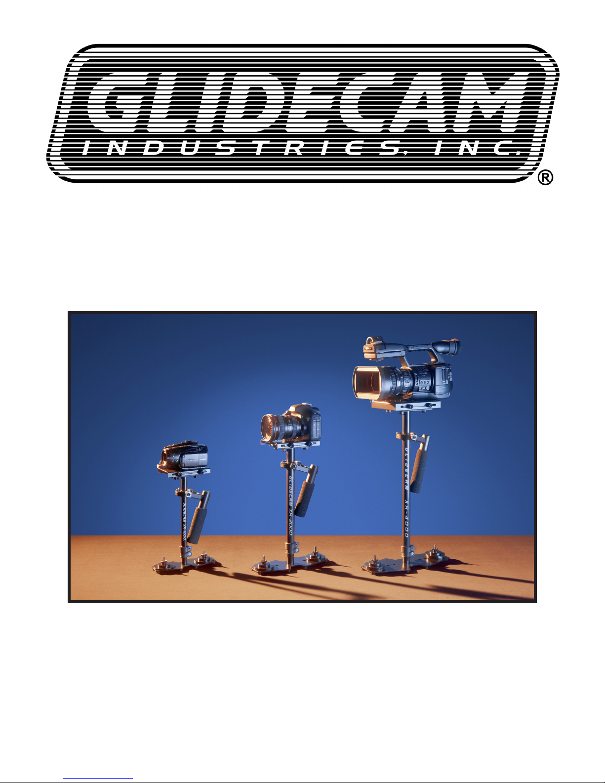
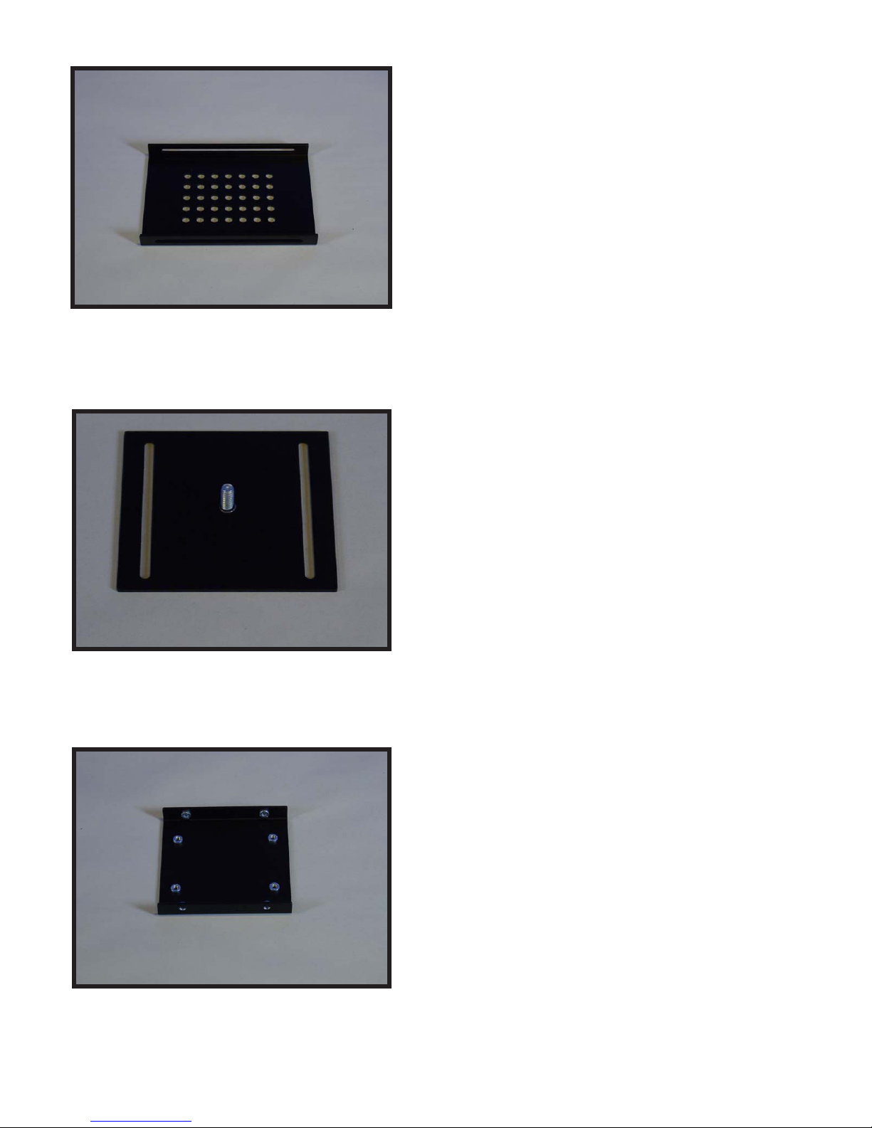
often associated with our competitors’ systems. The upper camera platform moves
back and forth, and side to side to quickly allow the balancing of your camera in
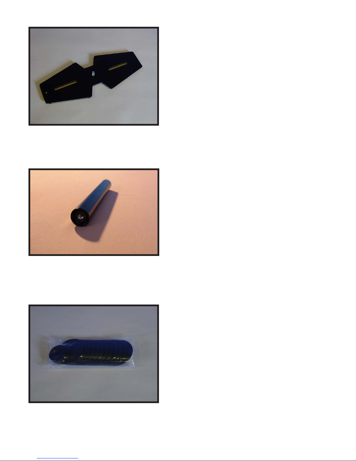
relationship to the counterweights. By varying the amount of counterweight disks on
the base platform, the Glidecam XR-SERIES can support any camcorder weighing
up to 3 pounds (XR-1000) six pounds (XR-2000) and 4 to 10 pound (XR- 4000).
While the Glidecam XR-SERIES is in essence a very simple device, its simplicity
doesn’t lend ease in answering that often asked question, “how does it work?” To
answer this question completely would require delving into Newtonian Physics. We
would have to explain - center of gravity displacement, inertia, friction and angular
motion reduction etc. However, a quick answer reveals the Glidecam XRSERIES
works by isolating your hand and arm’s motions from your camera, while your camera
is balanced in a relatively motionless state.
The Glidecam XR-SERIES requires practice and understanding to achieve
professional looking results. We highly recommend that the user read this manual
thoroughly before setting up and operating the Glidecam XR-SERIES. Doing so
will save you time, and will minimize the risk of damage to your camcorder or the
Glidecam XR-SERIES. It is important to perform and follow the Set-up and Operation’s
procedures in the proper sequence, so as to avoid both frustration and a possible
accident.
If you have need of any technical assistance, you can call our Technical Support
Line at 1-781-585-7900, Monday through Friday between the hours of 9:00 am and
5:00 pm, Eastern Time.
We’re sure that once you have your Glidecam XR-SERIES up and running, you will
nd years of enjoyment with it.
#1 INTRODUCTION
3

4
Figure 1
When you unpack your Glidecam XR-SERIES you
will see that it is not completely assembled.
Contents of the Glidecam XR-SERIES shipping box
include;
OPERATION MANUAL
XR-SERIES CENTRAL POST
HEAD PLATE
MID PLATE
BOTTOM PLATE
BASE PLATFORM
TELESCOPING POST
HARDWARE BAG
COUNTER WEIGHT DISCS
TOOLS NEEDED: You will need a Standard and
Phillips Head Screwdrivers. (Not included)
#2 GLIDECAM XR-SERIES PARTS AND
COMPONENTS
NOTE: The TELESCOPING POST comes
inserted into the CENTRAL POST when
shipped.
Figure 2
This is the Glidecam XR-SERIES CENTRAL POST
with attached gimbal assembly.
Warning – Do not tighten the factory settings on
the gimbal, handle, and yoke. The yoke and handle
should remain loose just as it is shipped to you.
Figure 3
These are the pieces that makeup the head assembly
of the XR-SERIES.
1) HEAD PLATE (shown left)
2) MID PLATE (shown center)
3) BOTTOM PLATE(shown right)

5
Figure 4
This is the HEAD PLATE. This is the plate that you’ll
be mounting your camera on.
NOTE: The HEAD PLATE for the Glidecam XR-4000 is different
than the one shown to the left. The XR-4000 HEAD PLATE has
3/8” and 1/4” mounting holes.
Figure 5
This is the MID PLATE.
Figure 6
This is the BOTTOM PLATE.

6
Figure 7
This is the BASE PLATFORM.
NOTE: The Glidecam XR-1000 has a smaller BASE PLATFORM
and the XR-4000 has a larger BASE PLATFORM.
Figure 8
This is the TELESCOPING POST.
NOTE: The Glidecam XR-1000 and XR-4000 have slightly
different sizes.
Figure 9
These are the 12 COUNTER WEIGHT DISKS & 4
SMALL COUNTER WEIGHT DISKS. (Shown in bag)
NOTE: The Glidecam XR-1000 has 8 LARGE COUNTER
WEIGHT DISKS.

Figure 10
This is the HARDWARE set. (Shown in bag)
NOTE: The Glidecam XR-1000 and XR-4000 has slightly
different HARDWARE. The XR-4000 has 2 3/8” CAMERA
MOUNTING SCREWS & WASHERS.
2 Rubber Washers
Bolts for Counter Weight Disks
Black umb Nuts
1 3/4”
1 1/2”
4 1/2” Washers
2 Camera Mounting Screws
12 Counter Weight Disks
8 Black umb Screws
4 Small Counter Weights
Figure 11
7

Figure 12
First, Get the BASE PLATFORM and the
TELESCOPING POST.
See Figures 7 and 12 for BASE PLATFORM &
Figures 8 and 13 for TELESCOPING POST.
#3 ASSEMBLING YOUR GLIDECAM
XR-SERIES
Figure 13
Note the threaded insert located in the bottom the of
TELESCOPING POST.
8
Note the threaded insert located in the bottom the of
TELESCOPING POST.
Figure 14

9
Figure 15
At this point your Glidecam XR-SERIES should look
like Figure 15 which is with the TELESCOPING
POST attached to the BASE PLATFORM.
Figure 16
Now nd a pair of bolts (example: ¼” x 20 x 1.5”) and
attach RUBBER WASHERS as shown in the photo
to the left. Other length bolts for more COUNTER
WEIGHT DISKS are available and can be used.
NOTE: Different length bolts are provided so you can use the
longer bolts for a taller stack of COUNTER WEIGHTS DISKS.
Figure 17
Now, insert the selected bolts (example ¼” x 20 x
1 1/2”) with RUBBER WASHERS bolts through the
slots in the BASE PLATFORM as shown in this
picture and repeat this procedure for the slot on the
other side of the BASE PLATFORM.

Figure 18
At this point your Glidecam XR-SERIES should look
like this photo.
NOTE: This is the Monitor Mounting Hole
Figure 19
Stack LARGE COUNTER WEIGHT DISKS and
center them over the bolts on the BASE PLATFORM
as shown in Figure 19.
NOTE: Different length bolts are provided so you can use the
longer bolts for a taller stack of COUNTER WEIGHTS DISKS.
NOTE: Heavy Cameras require more COUNTER WEIGHT
DISKS than light Cameras.
Figure 20
Place SMALL WEIGHT DISKS over COUNTER
WEIGHT DISK stacks.
10

11
Figure 21
Secure COUNTER WEIGHT DISKS with the BLACK
THUMB NUTS as shown in this photo and repeat
this procedure for the COUNTER WEIGHT DISKS
on the other side of the BASE PLATFORM.
Figure 22
Both COUNTER WEIGHT DISK stacks should now
be secured in place with the SMALL COUNTER
WEIGHT DISKS and BLACK THUMB NUTS as
shown in this photo.
Figure 23
Now, insert the TELESCOPING POST and attached
BASE PLATFORM up and into the XR-SERIES
CENTRAL POST.
The TELESCOPING CLAMP should be facing the
back-end of the BASE PLATFORM, opposite the
monitor mounting hole, which is in the front of the
BASE PLATFORM.
Monitor Mounting Hole
should be in front.
Telescoping Clamp’s
“Adjustment Knob”
Shown aligned
Incorrectly.
Telescoping Clamp’s
“Adjustment Knob”
should be in back.

12
Figure 24
The TELESCOPING CLAMP may have to be re
aligned on the CENTRALPOSTas the factory settings
may not be lined up. To realign the TELESCOPING
CLAMP use a hex key to loosen the clamp, realign
and then tighten.
Figure 25
Securely tighten the “Adjustment Knob” on the
TELESCOPING CLAMP by rotating the Knob
clockwise as shown in Figure 25.
The “Adjustment Knob” should only be
hand tightened.
WARNING: DO NOT OVER TIGHTEN
THIS KNOB.
Telescoping Clamp’s
“Adjustment Knob”
Shown aligned
correctly.
Figure 26
At this point this is what your XR-SERIES should look
like Figure 26. Which is with the CENTRAL POST
with TELESCOPING POST, BASE PLATFORM, and
COUNTER WEIGHT DISCS.

13
Figure 27
This is a photo of the insert in the top of the CENTRAL
POST.
Figure 28
Rotate and screw the BOTTOM PLATE into the insert
in the top of the CENTRAL POST.
Figure 29
Tighten the BOTTOM PLATE to the top of CENTRAL
POST to ensure a tight t.

14
Figure 30
Now place the MID PLATE on top of the BOTTOM
PLATE.
Figure 31
Insert the BLACK THUMB SCREWS through the
slots in the BOTTOM PLATE and into the threaded
inserts in the bottom of the MID PLATE.
Figure 32
At this point you should have four BLACK THUMB
SCREWS securing the MID PLATE to the BOTTOM
PLATE.
In the next section (Section #3) you’ll be attaching
your HEAD PLATE and attached camera to the MID
PLATE.

15
#4 ATTACHING YOUR CAMERA TO THE
GLIDECAM XR-SERIES
Figure 33
***PLEASE NOTE*** These photographs show the
Glidecam 2000 PRO for illustrative purposes.
Now it’s time to attach your camera to the Glidecam
XR-SERIES.
Roll camera on pen to nd the center of gravity, if
needed.
Figure 34
First, nd the threaded insert on the bottom of your
camera.
THREADED INSERT
Figure 35
Remove the HEAD PLATE from the Glidecam XR-
SERIES and with the camera placed upside down
in your lap align the appropriate hole in the HEAD
PLATE with the threaded insert in the bottom of the
camera.
As shown in Figure 36.

16
Figure 36
The HEAD PLATE should be in alignment and square
with the bottom of the your camera.
Rubber or tape can be used as a gasket if needed.
Also, the Manfrotto 394, 3273, or 577 quick release
plates can be used. The Manfrotto 3273 and 577 are
good for longer cameras.
Figure 37
Find a CAMERA MOUNTING SCREW (see Figure
11) and ¼” washer and use these to attach the HEAD
PLATE to your camera.
Figure 38
Place your camera upside in your lap and with the
HEAD PLATE in place use a at head screwdriver to
secure the HEAD PLATE to your camera using the
CAMERA MOUNTING SCREW you’ve just selected.

17
Figure 39
The HEAD PLATE should be secured and square
with the camera.
NOTE: If you have a Video Camcorder or Film Camera that is
larger than the one used in this Manual, then you might wish to
rst nd the true front to back center of gravity of your Camera
by rolling the base of your Camera on a pen, then mark this
point on your Camera’s side with small piece of tape or a grease
pencil, and then use this marking to center the HEAD PLATE
over your Camera’s center of gravity.
Figure 40
Now connect your camera and the attached HEAD
PLATE to the MID PLATE.
Figure 41
Insert the remaining four BLACK THUMB SCREWS
through the slots in the sides of the HEAD PLATE
and into the inserts in the MID PLATE.

18
#5 BALANCING YOUR GLIDECAM XR-SERIES
Figure 42
Before you begin the balancing process check for
the following:
1) Camera is securely attached to HEAD PLATE.
2) Lens cap has been removed.
3) Camera battery is connected.
4) Flip out LCD is in it’s operating position.
(if applicable)
5) Telescoping clamp has been tightened.
6) All 8 BLACK THUMB SCREWS in place and
secure.
Figure 43
BALANCING THE HORIZONTAL AXIS
Now that your Glidecam XR-SERIES is assembled
properly, and your camera is securely attached to
the HEAD PLATE, you can now test the horizontal
balance.
The objective in obtaining correct horizontal balance
for the XR-SERIES is to allow the camera to remain
level during operation, given you are not applying
either a pan, tilt, or roll type of hand pressure to the
XR-SERIES. In other words, if the XR-SERIES is
horizontally balanced correctly, then the camera will
remain level, and the CENTRAL POST will remain
vertical unless you intentionally position the XR-
SERIES otherwise.
If the XR-SERIES is horizontally balanced correctly
it will always return to a level and vertical position
after you release any pan, tilt, or roll pressure on the
CENTRAL POST.

Figure 44
The best way of adjusting the horizontal balance is
to move the center of gravity of the camera. This can
be accomplished by either repositioning the camera
on the HEAD PLATE, or by adjusting the position of
the HEAD PLATE, either front to back or side to side
with the camera on it.
When checking the horizontal balance you want to
make sure that you’re picking up the XR-SERIES
from a at and level surface (i.e. a table) and that
you let the XR-SERIES hang freely as you hold
it. If the XR-SERIES is balanced correctly on its
horizontal axis, then it will be level and upright, with
the CENTRAL POST in a virtually perfect vertical
position, as pictured in Figure 43.
If the XR-SERIES tilts to the front (see Figure 44), then you will have to loosen up the BLACK
THUMB SCREWS on the sides of the HEAD PLATE and gently slide the HEAD PLATE back a
bit. If the XR-SERIES still tilts to the front, then move the HEAD PLATE more to the back.
If the XR-SERIES is tilting to the back, then move the HEAD PLATE to the front. Always secure
the BLACK THUMB SCREWS after any adjustments.
If you cannot get the front to back axis balanced with this method then try remounting your
camera to a different hole in the HEAD PLATE. Once you achieve correct horizontal balance for
the front to back axis, you can tighten the BLACK THUMB SCREWS that control the movement
of the HEAD PLATE.
19

20
Figure 45
If the XR-SERIES leans to the right, then you will have to loosen
up the BLACK THUMB SCREWS on the bottom of the BOTTOM
PLATE and gently slide the MID PLATE over to the left a bit. If the
XR-SERIES leans to the left, then move the MID PLATE to the right.
Always secure and rmly tighten the BLACK THUMB SCREWS after
any adjustment.
After adjusting the side to side balance as mentioned above you
might have to go back and readjust the front to back balance to
obtain a ne balance of the whole system. You can use your eyes to
judge for correct horizontal balance, or you can use a bubble level
to ensure that the XR-SERIES has correct horizontal balance. The
Horizontal Balance of the XR-SERIES becomes less sensitive, as
the XR-SERIES becomes increasingly bottom heavy and conversely,
the horizontal balance becomes very sensitive, as the XR-SERIES
progresses towards correct vertical balance.
Also, another way of ne tuning the horizontal balance is to move
the COUNTER WEIGHT DISKS back and forth, or side to side on
the BASE PLATFORM. There are slots on the BASE PLATFORM to
help with this task. Also, replacing the WEIGHT DISKS away from
the CENTER POST on the BASE PLATFORM will increase panning
stability. Make sure to tighten the WEIGHTS down after you move
them.
NOTE: The Horizontal Balance of the XR-SERIES becomes less
sensitive as the XR-SERIES becomes increasingly bottom heavy,
and conversely, the horizontal balance becomes very sensitive, as
the XR-SERIES progresses towards correct vertical balance (see
next section).
Figure 46
This manual suits for next models
3
Table of contents
Other Glidecam Camera Accessories manuals