GlideTrak Indoor Trainer User manual

GlideTrak Assembly & Set Up
1
Manual for GlideTrak at Home

GlideTrak Assembly & Set Up
2

GlideTrak Assembly & Set Up
3
TABLE OF CONTENTS
GlideTrak Assembly Instructions……………………………………………. Pg. 4
Wheels …………………………………………………………………………. Pg. 5
Frame ……………………………………………………………….……… Pg.5 – 8
Seat Assembly …………………………………………………………… Pg. 9-10
Seat Assembly Placement …………………………………………….……. Pg. 11
Seat Set-Up Instructions ………………………………………………… Pg. 12-15
Unweighting the body …………………………………………………….… Pg. 16
Using the Ratchets ……………………………………………….…………. Pg. 18
Seat Assembly Adjustment …………………………………………………. Pg. 19
Evaluate “unweighting” position ……………………………………………. Pg. 20
Dismounting the GlideTrak …………………………………………………. Pg. 21
Reset Ratchets after workout ………………………………………………. Pg. 22
GlideTrak Assembly Tool List, Parts Identification ………………….... Pg. 23-26

GlideTrak Assembly & Set Up
4
3. For assembly: each part of the GlideTrak frame has several stickers with a letter. There is a
sticker with a letter placed on the end of every part of the GlideTrak.
GlideTrak™
Assembly Instructions
1. The GlideTrak should be
assembled in the room where you
will use your treadmill and
GlideTrak. Remove all GlideTrak
parts from the box and lay them
out onto your floor space. Remove
all packaging materials from each
part to prepare for assembly.
2. Refer to the Parts Identification
Pages (pgs. 23-26) to identify
each part. The photographs also
indicate the side of the part that
should face upwards to make
assembly as easy as possible.
Lay the parts on the floor as
shown in the Parts Identification
Guide (pgs. 23-26).
FRONT Mid-Section:
(Photo 1). with letter Iat top edge
and the letters A and Bat the
bottom edges.
Photo 1 Front Mid-Section
I
A
B
GlideTrak Fully Assembled

GlideTrak Assembly & Set Up
5
4. Assembly starts with the Wheels.
The 6 Wheels have Locking Levers. Lock the Wheels by pressing down the Locking Levers on
each Wheel. (Photo 2)
5. The 4 Base Legs have 6 threaded, Wheel Base-Plates. As illustrated in Photo 2, screw the
threaded post of each locked Wheel into the Base-Plate.
6. Locate the bag of hardware. The hardware includes 9-barrel bolts and 2 Allen wrenches.
(Parts Identification Guide pgs. 23-26)
Wheel
Wheel Post
Wheel Base Plate
Locking Lever
Sticker
with
letter A
Sticker
with
letter A
Bolt
Hole
Photo 3 Front Mid-Section
7. As noted, each part of the GlideTrak frame has several
stickers, with a letter placed on each end of the part.
Assembly will follow the ALPHABET IN ORDER.
8. Locate the Front Mid-Section part with the sticker
with letter A on one end.
9. Connect this section to the end of the Long Base Leg
with the matching sticker A. (Photo 3 & 4)
Lettered Stickers on parts must line up when frame
pieces are put together. (Photo 3)
Photo 2 Wheel
A
A

GlideTrak Assembly & Set Up
6
Sticker
with
letter C
Sticker
with
letter C
C
10. Follow the alphabet, matching the
stickers at the ends of the parts labeled
B to B, C to C, and D to D.
Only attach up to D for now.
(Photo 3 & 5)
Photo 4 Join parts labled A through D
C
C
Bolt Hole
Photo 5 Barrel Bolt placed in Bolt Hole
11. When joining the frame, align the Bolt
Holes and attach the Barrel Bolts in
the Bolt Holes. (Photo 3 & 5)
Use an Allen wrench in each hand to
tighten each Bolt. (not shown)
Barrel Bolts

GlideTrak Assembly & Set Up
7
12. Once sections Athrough Dare joined, you will have two sections of the GlideTrak frame as shown in
Photo 6.
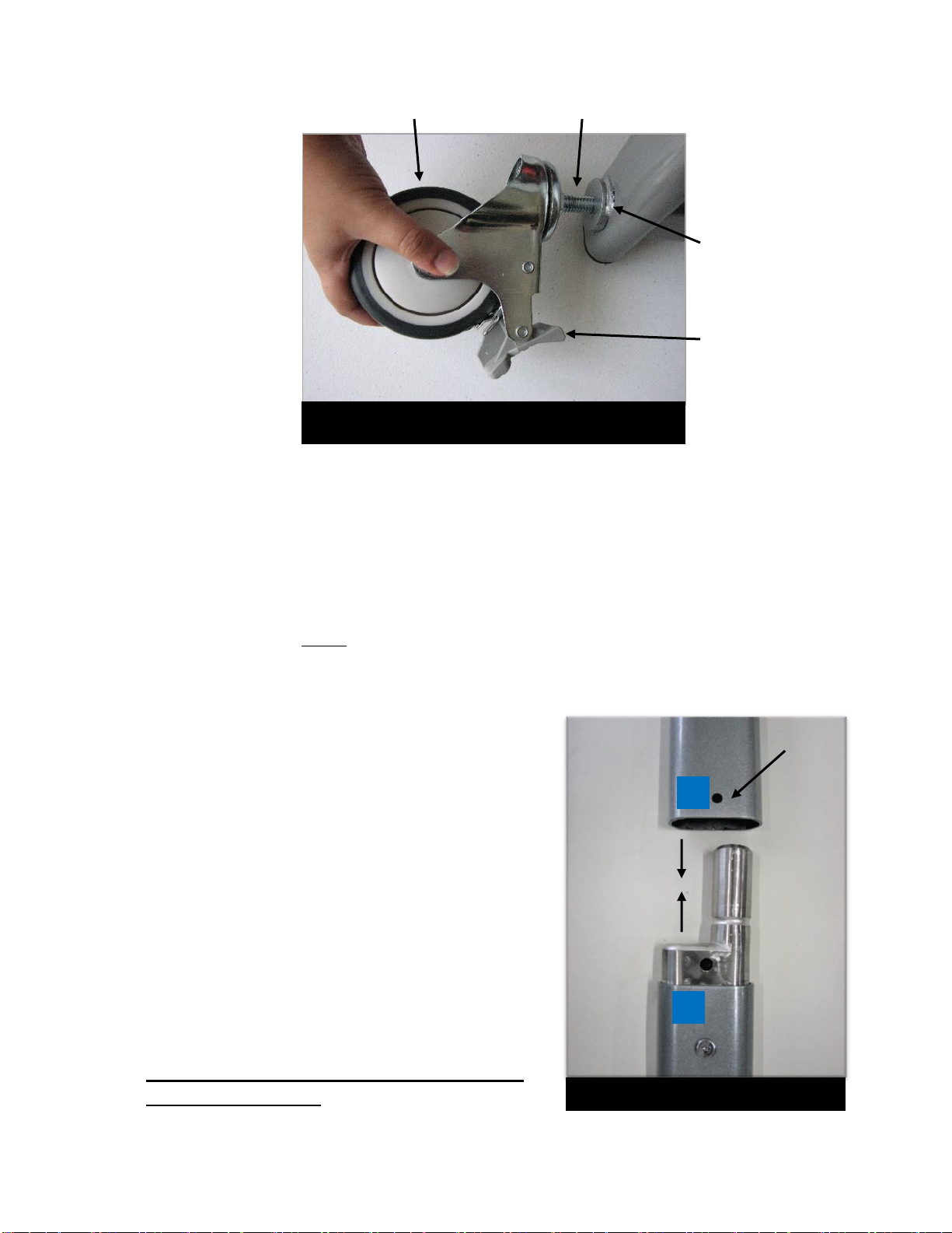
13. Slide the two sections together,
aligning stickers E to E and F to F.
The Frame Base will be assembled as
shown in Photo 7 Frame Base. It may
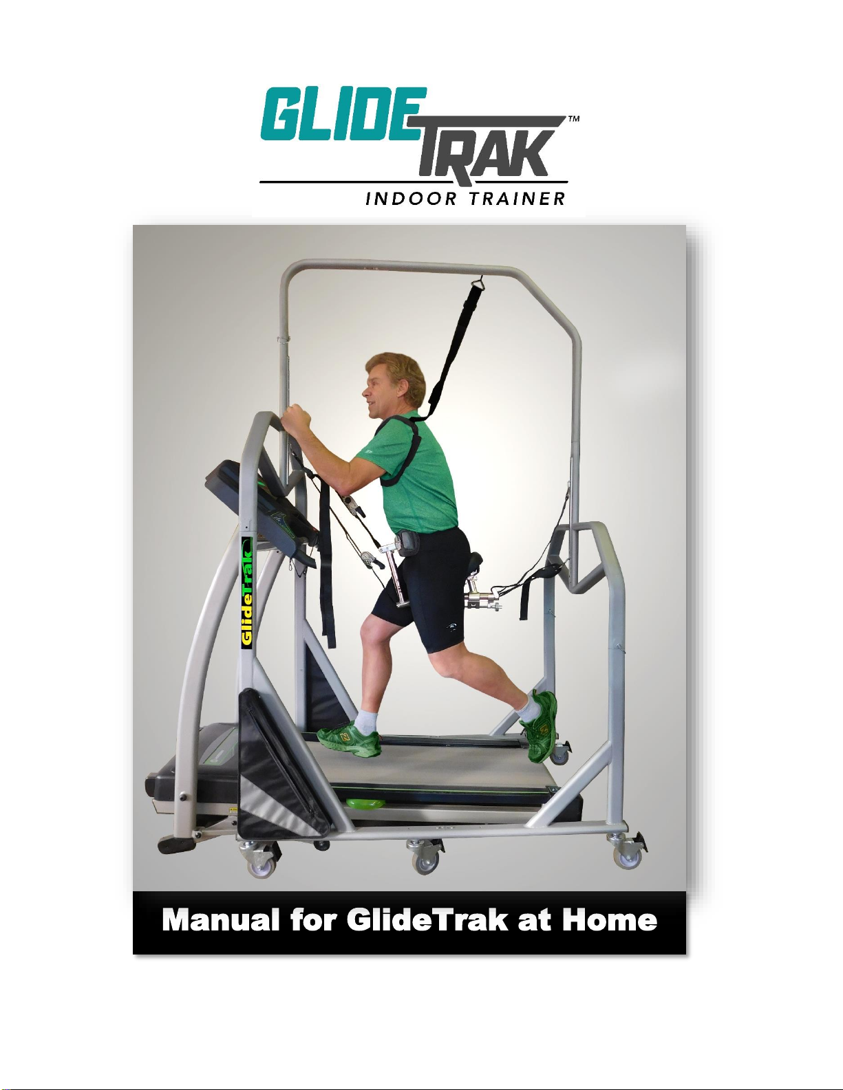
help to unlock the brakes on one
section before sliding the two sections
together. Once in place, re-lock the
brakes.
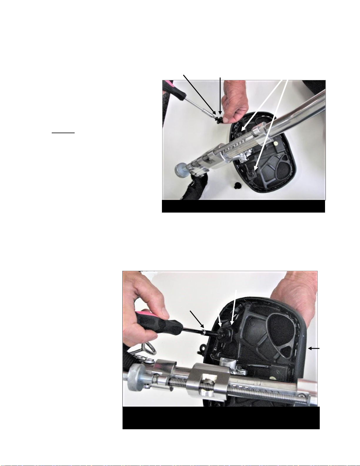
14. Once the frame is together, place and
tighten Barrel Bolts at E and F.
(Note: If basket pins were ordered, do not
use pins to connect base parts EE, FF or
GG. Only use Barrel Bolts to connect
base leg parts EE, FF, and GG)
Photo 7 Frame Base
F
E
Photo 6 Frame Sections
Rear Mid-Section
with letters C and D
at bottom edges and
letter H at top edge
Short Base Leg with
letters C or D at top
edge, and letters E
or F at bottom
edges
Front Mid-Section with
letters A and B at
bottom edges and letter
I at top edge
Long Base Leg with
letters A or B at top
edges, and letters E
or F at bottom edges
I
H
D
C
H
H
A
H
B
H
E
H
F
H
F
E

GlideTrak Assembly & Set Up
8
15. The Top Bar of the GlideTrak has 2 parts, a Curved Top Bar (for the front) and an Angled Top
Bar for the rear portion of the bar. (Photo 8 below, and Parts Identification Guide Photo 8 and
Photo 9, pg. 25). Join the two parts of the Top Bar joining the ends marked Gand G. Secure the
Top Bar with a Barrel Bolt. (Photo 5 and 8).
16. The ends of the Top Bar will join the Front and Back Mid-section posts. Attach the ends of the
Curved (front) Top Bar by joining Ito I, and attach the Angled Top Bar in the rear by joining
Hto H. (Photos 6 and 8) Align and insert Barrel Bolts into the Top Bar as shown previously in
Photo 5.
17. Tighten all in the frame with Allen wrenches to complete your frame assembly. (Photo 8).
18. Move the GlideTrak frame and center it over your treadmill. (If you wish, you may unlock the
wheels to move the frame; however, make sure that Wheels are re-locked after the GlideTrak is
in place).
Front: Curved Top
Bar with center
edge marked G
and front end
marked with the
letter I
Rear: Angled Top
Bar with center
edge marked G and
the back edge
marked with the
letter H
G
I
H
Photo 8 Top Bar joined with Front & Mid-Section

GlideTrak Assembly & Set Up
9
Now you are ready to assemble the Seat Assembly.
19. SEAT ASSEMBLY: Cut away any wrapping and plastic ties from the Seat Assembly. The
Seat Assembly Includes the Back Straps, Seat Post, Adjustment Rod, Hip Post, Hip Pad and
Front Straps. (Photo 8)
When you take it out of the box, the assembly will be in 2 parts. One piece is the bulk of
the Seat Assembly. The second piece is the Seat Pad with attached Seat Screws. To
complete the Seat Assembly, you only need to reattach the Seat Pad. You will need one
Phillips-head screwdriver for this task.
20. To reattach the Seat: Remove the 2 screws
and 2 washers from the back of the Seat Pad.
21, Insert the front of the Wire
Loop of the Seat
Assembly into the Wire
Slot on the back of the
Seat Pad.
(Photos 10 & 11)
Photo 9 Seat Assembly
Seat Pad
Hip Pad faces up
& front
Front Top Strap
Ratchet on
Front Bottom
Strap
Hip Post
Seat Post
Rear Straps
Seat Rail
Adjustment Rod
Photo 10 Seat Pad backview
2 Seat Screws & washers
Wire
Slot of
Seat
Pad
Photo 11 Seat Assembly Frame & detached Seat
Pad with screws and washers
Seat Pad
Seat Screw Hole
Seat
Screws
Wire Loop on Seat
Assembly
Wire Slot on
back of Seat Pad
Seat Screw
Hole

GlideTrak Assembly & Set Up
10
22. Once the Wire Loop is inserted into
the Wire Slot on the back of the
Seat Pad, the back of the Wire Loop
will sit directly over the Seat Screw
Holes.
Replace the Seat Screws back
into the Seat Screw Holes
CAUTION: Do not press down on the
screws as the threads inside the hole
may sink into the seat permanently.
Place a Seat Screw through a
Washer.
Place the Screws and Washer on
top of the Wire Loop and into the
Screw Hole. (Photo 12 & 13) Turn
the Screw clockwise to engage the
Seat Screw in the Seat Screw Holes.
Back of Wire
Loops Over
Seat Screw
Holes
Washer
Screw
Photo 12 Seat Pad (back view)
Back of Wire Loops
over Seat Screw
Washer
Screw
Seat Pad
Photo 13 Re-attaching the Seat to the Seat Assembly
The order is: Screw, Washer, Wire Loop, then Seat
23. Orient yourself with
the Seat Assembly,
noting the front, back,
up and down for the
Seat and Straps.
Note that Seat Pad is
up and towards the
back and the Hip Pad
will face up and
forward as in Photos
8 & 9.
You are now ready
for Seat Assembly
placement and
setting yourself up
on the GlideTrak.

GlideTrak Assembly & Set Up
11
GlideTrak™
Seat Assembly Placement and Set Up Instructions
24. The Seat, Bars, Straps, Hooks, and Hip Pad are collectively called the Seat Assembly.
(Photo 14)Once your GlideTrak has been fully assembled and positioned properly over the treadmill,
you are ready to attach the Seat Assembly.
Photo 14 Seat Assembly
Seat Pad
Hip Pad
Front Top Strap
Ratchet on
Front Bottom
Strap
Hip Post
Seat Post
Rear Straps
Seat Rail
Adjustment Rod
25. Review Photo 14 to identify each part of the
Seat Assembly and orientation (front, rear, up
and down).
26. To start, use the Seat Adjustment Knob to
move the Seat along the Seat Rail until the front
edge of the Seat Post is at #4 at the numbered
bar under the Seat Rail.
(Smaller framed individuals may set this to #3.
Larger framed individuals may set to #5 to start)
27. The Hip Post has 8 holes. Set the Hip Post to
the 4th hole from the top.
To do this, press in on the pins on the Hip Post
and, using your other hand, grasp the Hip Pad
and slightly twist and move the Hip Post rod up
or down. Set the pin into the hole that is the 4th
hole from the top.
Front Mid-
Section
Post with
holes for
front strap
hooks
Rear Mid-Section
Post with holes for
back strap hooks
Photo 15 GlideTrak
Hip Pad
is up and
faces
forward

GlideTrak Assembly & Set Up
12
Seat Set Up Instructions
28. Pick up the whole Seat Assembly and orient the
seat so that the Hip Pad is up and towards the
front of the GlideTrak (the taller end) and the Seat
Pad is up and toward the rear of the GlideTrak, as
seen in Photo 15.
29. Note that the posts of the Front Mid-Section and
Rear Mid-Sections have holes in them that face
inward on the GlideTrak. These holes are for
the Strap Hooks on the front and back of the
Seat Assembly. ( Photos 14 & 15)
30. Locate the Top Front Strap Hook which
comes off the Seat Assembly at the top of the
Hip Post. (Photo 16)
31. Being cautions not to step on the Straps, step
up onto the treadmill and stand beside the post
of the Front Mid-Section.
32. Note which hole on the Front Mid-section
post is at the level of your chin.
(Photo 16)
33. Insert the Top Front Strap hook into the hole
on the Front Mid-Section post that is at the level
of your chin. (Photo 16)
NOTE: It is easier to insert the Strap Hooks
into the holes if you turn the Strap Hook
sideways. (Photo 16)
34. The Bottom Front Strap Hook should then
be placed in the hole in the Front Mid-Section
post that is 2 holes below the Top Front
Strap Hook. (Photo 17)
Photo 16 Placing Front Top Strap
Hook at level of chin
Photo 17
Placing Strap Hooks in Holes
Front Mid-
Section
Post Hole
at level
of chin
Front Top &
Bottom Strap
Holes for
Hooks on
Front Mid-
Section
Post
Hook

GlideTrak Assembly & Set Up
13
Rear Mid-Section
with Strap Hook
in Hole one level
above the wrist
Photo 18 Place Bottom Rear Strap Hook
one hole above level of your wrist
35. To determine the placement of the Rear Seat
Assembly Straps, stand on the treadmill beside
the post of the Rear Mid-Section of the GlideTrak
frame.
36. Relax your arm by your side and note which
hole on the Back Mid-Section post is one hole
above your wrist.
(photo 18)
37. Insert the Bottom Rear Strap Hook into the
hole one level above your wrist.
(Photo 18)
The Bottom Rear Strap will be tight during
exercise and will support you.
38. Insert the hook of the Top Rear Strap in the Mid-
Section post hole that is 3 holes above the
Bottom Rear Strap Hook
Photo 19 Safety Shoulder
Harness
Back
Front
39. Shoulder Harness Instructions: Shoulder Straps
The Safety Harness hangs from holes in the top bar of the
GlideTrak and limits side to side movement of the body.
Insert the hook of the Shoulder Harness into the 5th hole from the
front. (Photo 19)
Use the strap at the top of the harness to adjust the loops to fit
loosely beneath each arm.
The Shoulder Straps are NOT for support. You should not feel any
upward pull from the Straps.
5th Hole from the front

GlideTrak Assembly & Set Up
14
Photo 20 Black Metal Buckle on Straps
Photo 21 Releasing a Strap
Photo 22 Loosen a Strap by
pressing center of Metal Buckle &
pulling tight end of Strap towards you
Black
Metal
Buckle on
Front
Strap
Ratchet on
Front Strap
Press Center
of Black Metal
Buckle
Tight
end of
Strap on
bottom
Metal Buckle
Tight end of Strap
towards you
Now we will set you up in the Seat.
40. RELEASE THE FRONT STRAPS:
NOTE: There is a Black Metal Buckle and a
Ratchet on the front Straps. (Photo 20)
You will use the Black Metal Buckles
and Straps for all major adjustments.
41. Hold the Black Metal Buckle on the Bottom
Front Strap. (Photo 21)
In this position, the tight end of the Strap will
be on the bottom, and the free end of the
Strap will be on top. (Photo 21)
42. Loosen the Bottom Front Strap first to
lower the Seat.
To loosen the Strap, press the center
Release Button in the middle of the Black
Metal Buckle to release it.
(Photo 21 &22)
At the same time, use your other hand to pull
the tight (bottom) end of the Strap towards
you.
(Photo 21 & 22)

GlideTrak Assembly & Set Up
15
Photo 25 Tightening Strap
Photo 24 Seat Assembly
cradles pelvis
Photo 23 Seat lowered to
treadmill
Pull top (loose)
end of Strap
towards you, and
lift the tight part
of the Strap
(bottom) upward
43. Repeat this process, releasing the Front Straps until the Seat
is lowered close to the treadmill. (Photo 23)
44. Once the Seat is lowered, carefully step over the Seat, so
that your legs straddle the Seat Assembly.
45. Grasp and Lift the Seat Assembly up so that the Seat
Assembly cradles your pelvis. (Photo 24)
Keep in mind that you will fit more snugly into the Seat
once the straps are tightened and you are “Unweighted.”
46. With the Seat cradling your pelvis, take a small step forward
to ensure that the Lower Rear Strap is taught.
Now we will tighten & adjust the Front Strap
47. Tighten the Front Straps by pulling up on the on the tight
(bottom) part of the Strap (right hand in Photo 25). At the
same time, you will use your other hand to pull down on
the free end of the Strap. (left hand, Photo 25).
48.Holding onto the arms of the treadmill for safety, squat down
to settle your pelvis into the Seat.
49. Return to standing on the treadmill.
Keep your back, hips, and knees
straight, your feet slightly behind you,
and your weight forward on the balls of
your feet. (Photo 32)

GlideTrak Assembly & Set Up
16
Photo 26 Lean forward while tightening
the Front Top Strap
Photo 27 Lean backward tightening
the Bottom Top Strap
Unweighting the body
50. Rocking forward and back while
tightening the Straps allows you to
begin to unweight the body.
Lean forward onto your toes with
the weight on the balls of your
feet and firmly tighten the Front
Top Strap.
(Photo 26)
51. Stand again with straight legs
beneath you.
Now lean back slightly with your
weight on the heels of your feet,
and firmly tighten the Bottom
Front Strap. To lift your body
weight, you must pull firmly on
the Straps.
(Photo 27)
52. Repeat steps 50 and 51, 2-3 times
to until the 2 front Straps are quite
tight.

GlideTrak Assembly & Set Up
17
Photo 28
Go up on Tip Toe
Photo 29 Tighten Strap
Photo 30 Tip Toe Hip Hop
53. You will further unweight your body by
doing something called the “tip-toe hip-
hop”.
There are 2 actions that you will need to
do simultaneously.
One: Go up on your tip toes.
(See photo 28)
Two: Tighten the front straps as you did
previously. (See Photo 29)
To perform these 2 motions simultaneously,
tighten the Straps while you go up on your
tip toes, pulling hardest on the Straps when
you are at the highest point on tip toe.
(See Photo 30)
Note: For orthopedic conditions such as
bone or joint problems, the goal is to unweight
your body about 85-90% or just enough so that,
with your legs extended beneath you, your feet
should just skim the surface of the treadmill.
Note: For neurologic conditions such as
stroke or Parkinson’s disease; the goal is to
unweight your body about 20-35% so that you
remain grounded on the treadmill.

GlideTrak Assembly & Set Up
18
Photo 31 Tightening the Ratchet
Photo 32 Proper Standing Position
Using the Ratchets
54. For further unweighting, you may use the Ratchets on
the front 2 Straps.
To use the Ratchets, pull up on the Black lever.
Tighten both the top and bottom Ratchet equally to start.
(Photo 31)
This will lift your body further off the treadmill.
Getting a sense of being “Unweighted”
55. Simply get a sense of being “unweighted”. Keep in
mind that lifting your body weight (being “unweighted”) is
a new feeling as you have probably never been
unweighted before.
56. Turn the treadmill on to a reasonable speed for you, a
slow walking pace will do.
57. The Seat should support you in a standing position.
Keep your legs straight beneath you, your back,
hips, and knees straight, your feet slightly behind
you, and your weight forward on the balls of your
feet. (Photo 32)
58. Walk unweighted for 5-10 minutes.
59. Do not worry about the Seat being perfect. Once you have begun to use the treadmill and GlideTrak,
you will adjust the Seat gradually until you find your individual, ideal setting.
60. Once you have walked for 5-10 minutes, we highly recommend you dismount the
GlideTrak (as instructed below) and walk around normally for several minutes.
61. Then, beginning at step 44, set yourself back up on the GlideTrak and continue on to the Seat
Assembly adjustment instructions below.

GlideTrak Assembly & Set Up
19
Photo 33 Hip Pad position
allows hip flexion
Photo 34 Seal supports you
but allows hip extension
Photo 35 Turn Adjustment Knob
forward or back to move the seat
Photo 36 Adjusting Hip Pad to
4th Hole
Hip Pad across
your lap but
allows hip
flexion
Seat Assembly Adjustment
62. The Seat should allow you to flex & extend your
leg as you walk. (See Photos 33 & 34) Adjustment
is discussed below.
63. The Hip Pad should sit just at or above the hip
bones in front (like a seatbelt) but allow you to flex
your hip as you walk. (See Photo 33) Adjustment
is discussed below.
64. To adjust the Seat pad: Step out of the Seat. Use
the seat Adjustment Knob (See Photo 35) to move
the seat forwards to give a tighter fit, or backwards
to give you more room.
65. To adjust the Hip Pad: Step out of the Seat. Press
in on the pins on the Hip Post (See Photo 36) and
move the Hip Post Rod up or down to the position
that affords you the most comfort.

GlideTrak Assembly & Set Up
20
Evaluate your position and Adjust “Unweighting”
The GlideTrak is new to you and your body. Unweighting your body is an amazing way to regain and
maintain cardiovascular and muscular fitness without the damaging effects of impact on your joints or
fear of falling. However, your body must adjust to this technique. Following written instructions to learn
how to swim or to pitch would feel unnatural and would invariably take some practice and adjustments
before you were able to float and do a breast stroke or throw a pitch. Either way, your best bet is to relax
your body, give the GlideTrak a try, and work on adjusting the seat over your first few sessions.
66. Adjust the Seat Assembly so that your gait feels as natural as possible.
You should be in a standing position. (See Photo 32) Keep your back, hips, and knees straight.
Your feet should be slightly behind you, weight on your full foot, leaning slightly forward. Good
posture and looking straight ahead is helpful. In this position, you should feel supported in the Seat
Assembly, but you should also be able to walk, jog, or run with a natural gait and stride. (If possible,
get a video or evaluate your stride in a mirror.)
67. To adjust the amount of “unweighting” (adjust the impact on your joints):
•Repeat steps 50 and 51 to tighten the front Straps further and lift more of your weight off the
treadmill.
•Adjust the amount of incline on the treadmill. More incline = More impact. Increasing the
treadmill incline (bringing the treadmill higher) allows for more contact of your feet on the treadmill
and will increase the impact across the joints of the lower extremities. Less incline = Less
impact. Decreasing the amount incline (bring the treadmill lower) allows for more support and
suspension from the Straps, and therefore allows more of our body to be “unweighted.”
•It is ideal to be able to adjust your body “unweighting” during exercise. If the treadmill allows,
PRIOR to starting your session, incline the treadmill several levels. Then follow steps 47 through
61. This will elevate you with the treadmill deck at the start of your workout. This allows you the
ability to adjust the incline up or down (and allows for controlled, variable impact on the joints)
during your workout.
•Shift your body weight. When you are exercising, you can make some subtle adjustments in
the amount of impact on your joints during exercise by simply leaning a bit forward or backward.
Try this and see what adjustments optimize your personal training program.
•Ratchets on the front Straps: Subtle adjustments can
be made by using the Ratchets on the top and bottom front
Straps. Tightening the Ratchets will increase the
amount of support provided by the Seat Assembly
(increase the amount of body “unweighting”).
(See Photo 36)
•Releasing the Ratchets will remove the Seat Assembly
support. To release the Ratchet, press down on the Center
Lever and open it all the way. Pull the Strap away from the
Ratchet so no slack remains. (See Photo 37]
Photo 37
Tightening a Ratchet
Table of contents
Other GlideTrak Treadmill manuals
Popular Treadmill manuals by other brands

PowerTrainer
PowerTrainer PT-333 owner's manual

ICON Health & Fitness
ICON Health & Fitness NordicTrack S20i user manual

Image
Image Advanced 3000 Treadmill manual

NordicTrack
NordicTrack NCTL15991 user manual

Sunny Health & Fitness
Sunny Health & Fitness SF-T7873 user manual

AbodeFit
AbodeFit WalkSlim 540 user manual

ICON Health & Fitness
ICON Health & Fitness PRO-FORM PERFORMANCE 600c user manual

Sole Fitness
Sole Fitness TT8 owner's manual

ICON Health & Fitness
ICON Health & Fitness PRO-FORM QUICKSTART 6.0 user manual

Spirit
Spirit XT 600 owner's manual

Christopeit Sport
Christopeit Sport TM 1 Go Assembly and exercise instructions

Casall
Casall Easy Run1.1T user manual