Step by step INPUT configuration example
INPUT ACTIVATION MODE
Let's assume that the desired INPUT ACTIVATION MODE configuration is SHORT CIRCUIT TO ALARM.
To obtain this configuration the following steps need to be taken:
STEP 1: Remove power from the module.
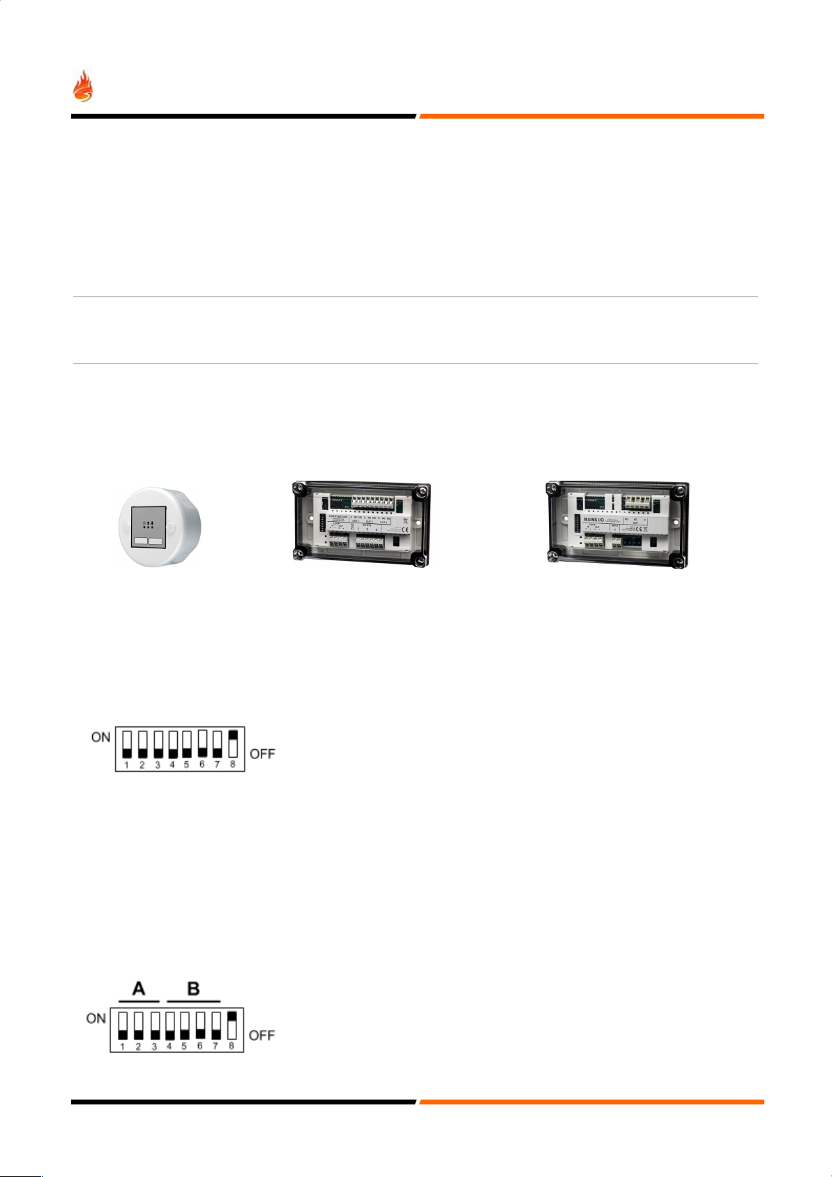
STEP 2: Set DIL Switched 1 to 7 to the OFF position and DIL Switch 8 to the ON position.
STEP 3: Power up the module. The two LEDs flashing alternatively will indicate that the module is in programming mode.
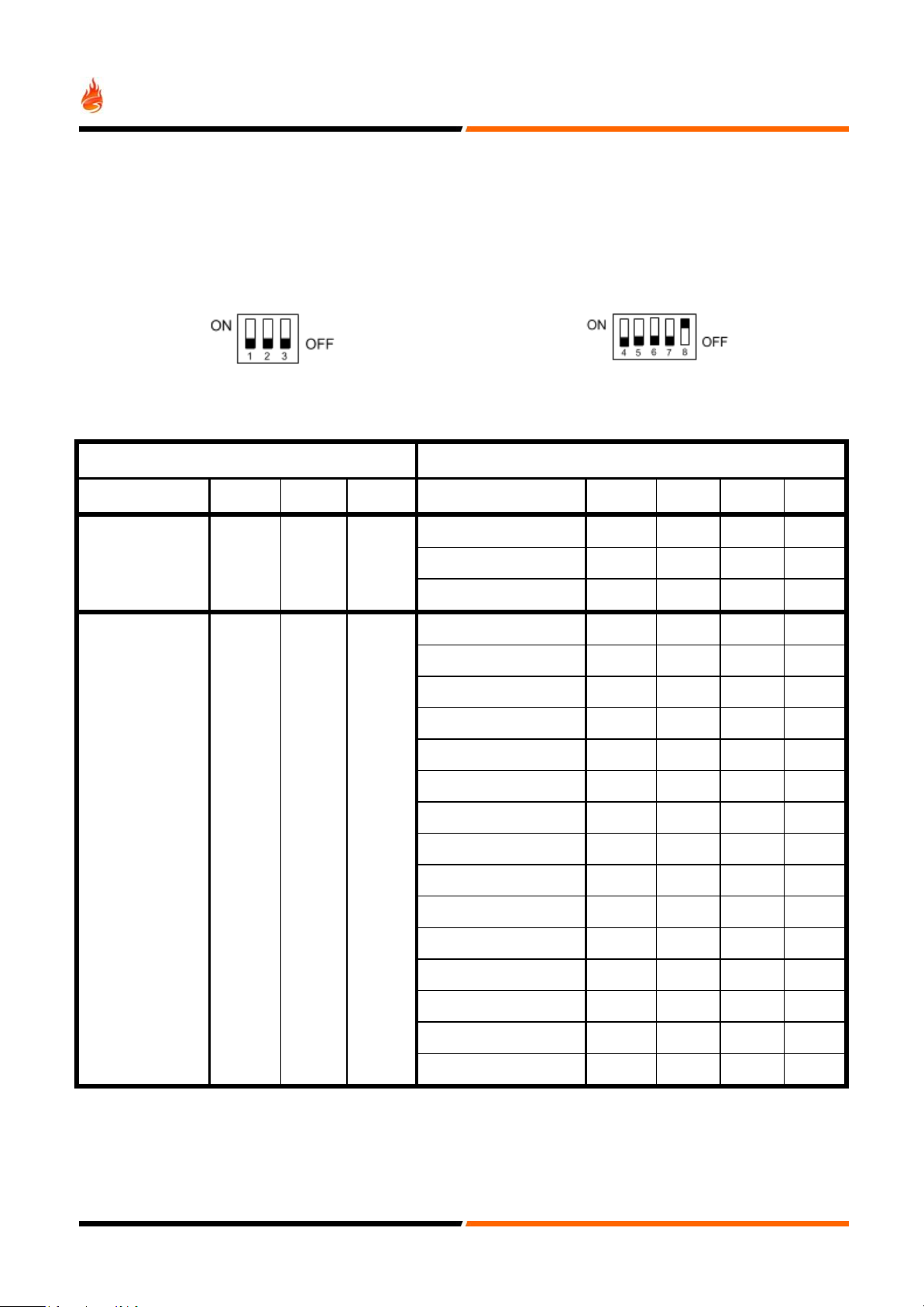
STEP 4: Set the DIL Switches 1 to 3 to INPUT ACTIVATION MODE (SW1: ON, SW2: ON & SW3: OFF).
STEP 5: Set the DIL Switches 4 to 7 to SHORT CIRCUIT TO ALARM (SW4: ON, SW5: OFF, SW6: OFF & SW7: OFF).
STEP 6: Set the Switch 8 to the OFF position. The Green LED will flash four times.
The module’s is now programmed to trigger an alarm when a short circuit is applied to the input.
INPUT DELAYED ACTIVATION FUNCTION
Let’s assume that a delayed input with a 70 seconds delay is needed.
In order to configure the timer, the following steps need to be taken:
STEP 1: Remove power from the module.
STEP 2: Set DIL Switched 1 to 7 to the OFF position and DIL Switch 8 to the ON position.
STEP 3: Power up the module. The two LEDs flashing alternatively will indicate that the module is in programming mode.
STEP 4: Set the DIL Switches 1 to 3 to INPUT DELAYED ACTIVATION FUNCTION (SW1: OFF, SW2: OFF & SW3: ON).
STEP 5: Set the DIL Switches 4 to 7 to 70s (SW4: ON, SW5: ON, SW6: ON & SW7: OFF).
STEP 6: Set the Switch 8 to the OFF position. The Green LED will flash 4 times.
The module’s Output Timer is now programmed to 120s.
INPUT LED BEHAVIOUR
The LED associated with each Input operates as follows:
In order to record new parameter value in the non-volatile memory, reset Switch 8 to the OFF position.
ONE ADDRESS MODE (3 I/O PLUS 2 and 3 Channel only)
There is a ONE ADDRESS MODE available for 3 I/O PLUS 2 and 3 Channel. In this mode, the module will monitor all inputs
but respond only with one address to the Addressable Panel. The module will report as follows:
●FAULT: If any of the inputs has a Short or Open circuit fault present the module will report analogue value 4 to the
Panel.
●ALARM: If any of the inputs has been activated, the module will repost analogue value 64 to the Panel.
● If there is no Faults or Alarms present, the module will report analogue value 16 to the Panel.
● If an output activation as been sent by the Panel all 3 outputs will activate.
6