Connection Diagrams
ZONES 1, 2, 3F & 3X
Four zones are available for detection, each zone has capacity for up to 32 smoke/heat detectors and an unlimited number
of manual call points. This may be restricted by local regulations.
An active end of line capacitor (10UF/50V bipolar) is supplied for each zone, as part of the monitoring circuit. This must be
fitted to the last device of each Zone. If a detection zone is unused, the end of line module must be connected at the panel, if
it’s not fitted, a fault will be indicated for that zone.
A typical detector circuit wiring layout is shown below. Please consult the device manufacturer's instruction manual for
detailed information.
If manual call points are wired on the same circuit as detectors, in order to comply with the requirements of BS5839 with
respect to head removal monitoring, detector bases should have a Schottky diode fitted, which permits manual call points to
continue to operate normally after a detector has been removed (see diagram). Manual call points should have a maximum
internal resistance of (470-680) Ohms in Alarm.
The wiring for each detector zone should be terminated in the relevant terminal blocks at the control panel and the cable
screens connected to earth.
NOTE:
Zone 3F is independent from extinguishing cycle. Upon activation by one detector or call point, only S1 output and
panel fire relay will be activated.
Zone 3X is dedicated for extinguishing cycle activation:
- Upon activation by one detector or call point, both S1 output and both panel fire relay will activate.
- S2 output and REM output will be activated according with the programmed extinguishing cycle.
S1 & S2 MONITORED OUTPUTS
These output/sounder circuits have a combined maximum current output of 1,85 Amps.
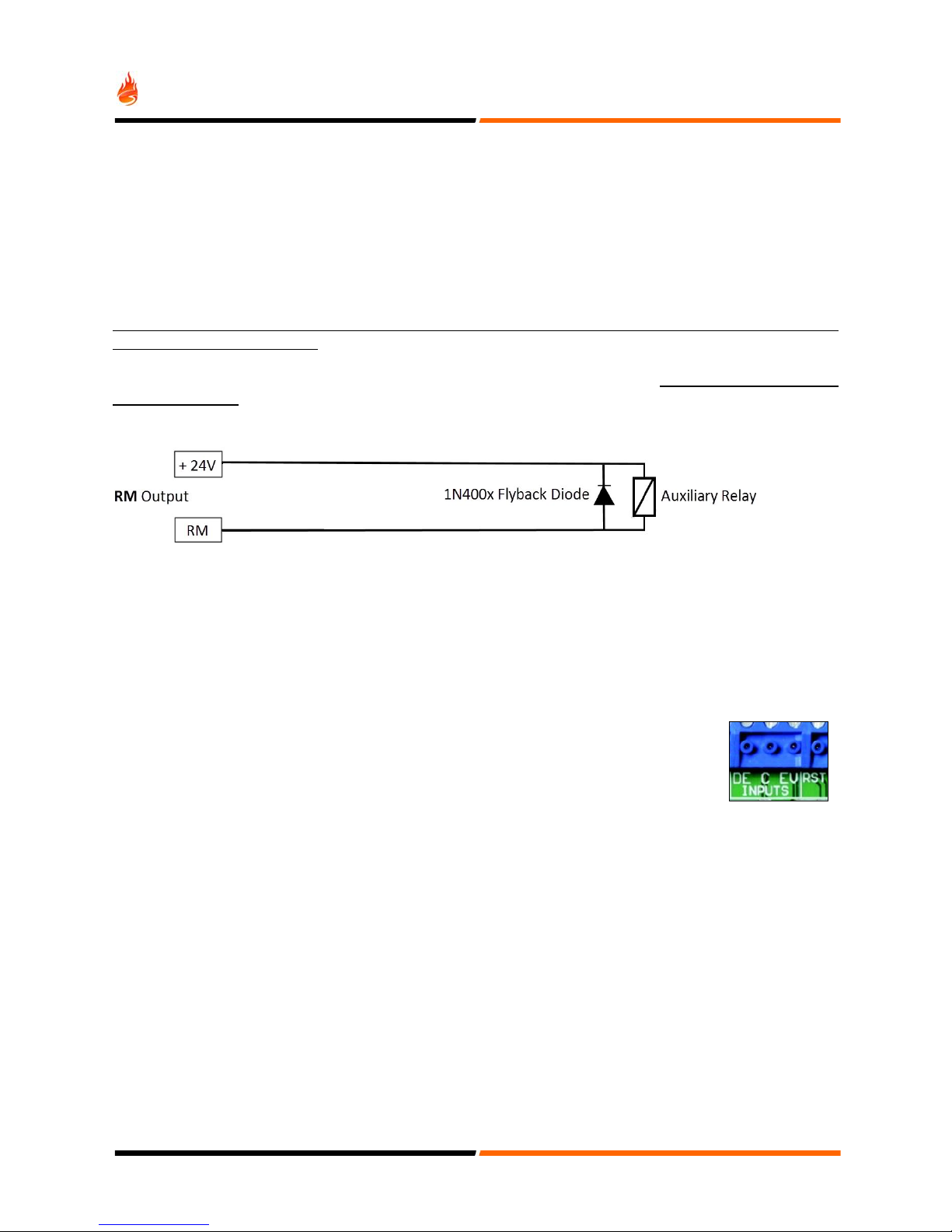
Connected devices (sounders, beacons, bells, pyrotechnic actuators, solenoids, relays, etc.) must be polarized,
non-polarized devices trigger a fault on the panel circuit. In order to mitigate this situation a polarization diode should be
added when using bipolar devices. With solenoids, relays and bells a flyback diode should also be present.
An end of line resistor (10K Ohm) which is supplied with the panel, must be inserted in the last device for monitoring. If a
sounder/output circuit is not used, the EOL resistor should be fitted in the respective control panel output.
The sounder circuits are protected against short circuits, the electronic fuse will reset when the short circuit is removed and
the control panel is reset.
8