Manufacturers of Fire Detection Equipment
www.globalfire.pt
INSTALLATION, OPERATION AND MAINTENANCE MANUAL - 10/2011
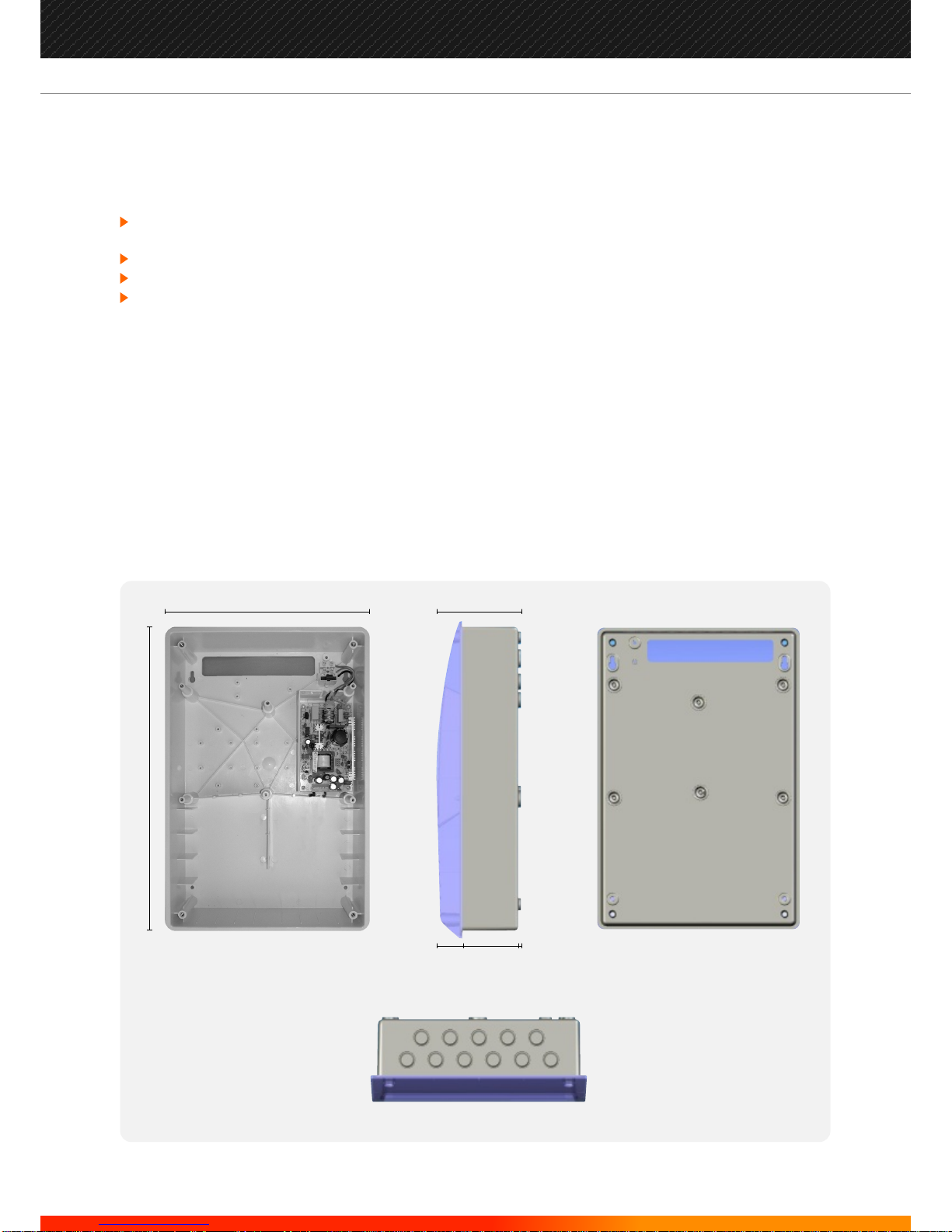
ORION - 2, 4, 8 ZONE FIRE ALARM CONTROL PANEL
Overview
Features
OptionalInterfaces
The ORIONis a 2,4and 8Zone microprocessor controlled conventionalFire Alarm ControlPanel withallthe
functionsnecessarytocontrolsmallandmediumsizefiredetectioninstallations.
Two,fourandeightzonenon-expandablecontrolpanels
Upto32conventionalsmokeand/orheatdetectorsperzone
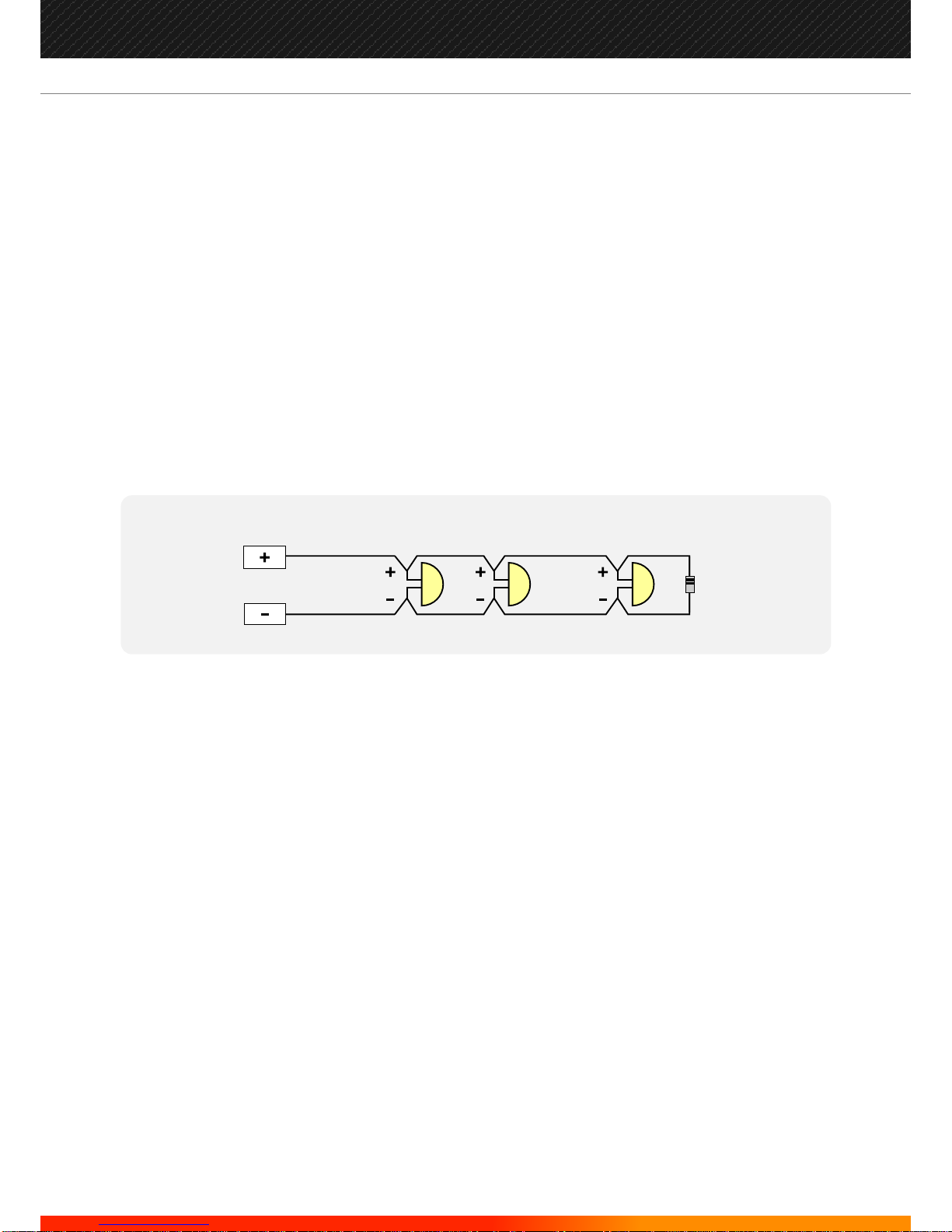
ActiveEndofLinemonitoring
Programmablenon-latchingzones
Programmabledelaytimerforsounderandrelayactivation. Maximum10minutes
(Day/NightFunction)
Delayedoperationselectableforeachzone
Zonecoincidenceprogrammableforadjacentzones
TwoAccessLevels.Selectablebyfixedcodeentry
Onemantest
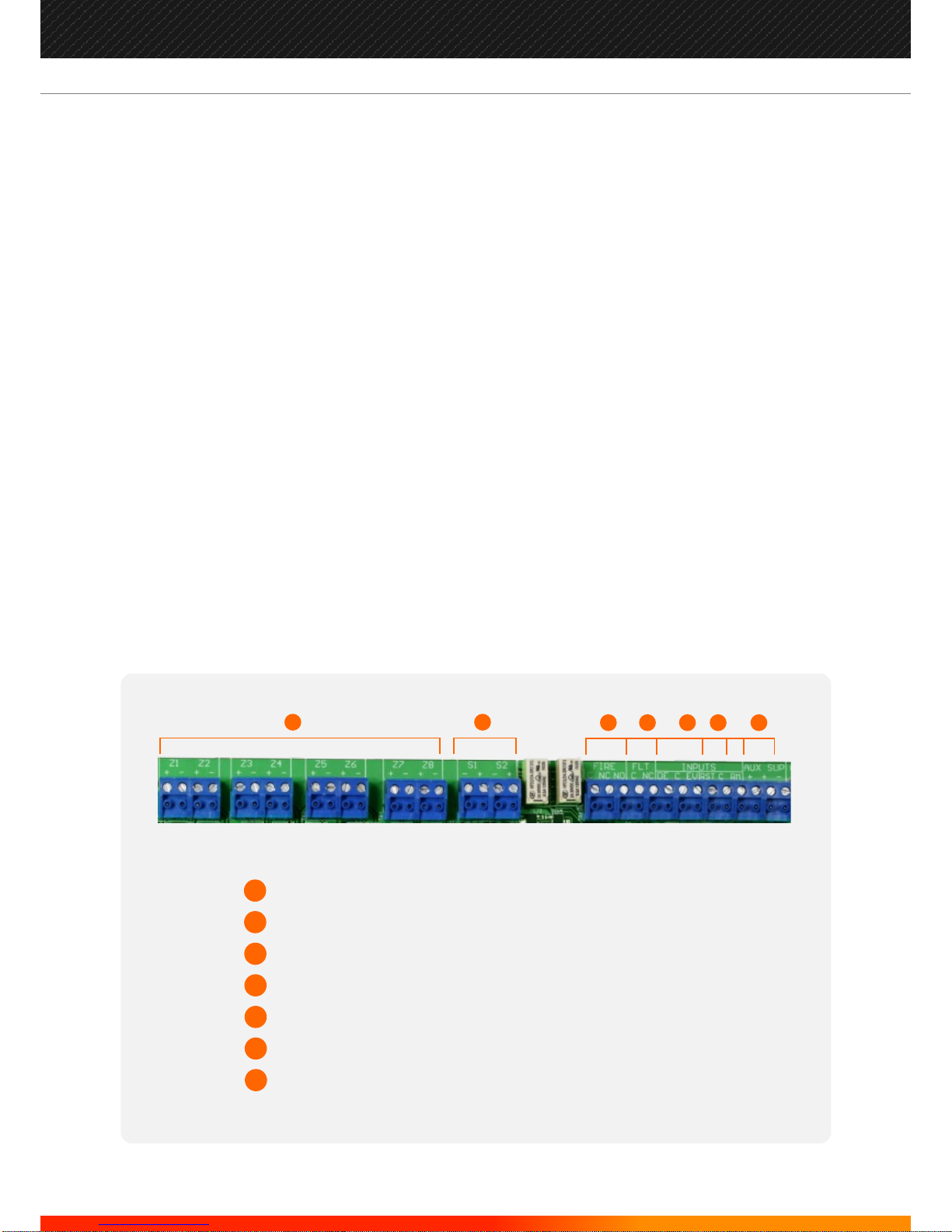
Supervisedauxiliary24voltoutput
2supervised/monitoredsoundercircuits
3RemoteinputsforClasschange,Day/NightOperationandremotereset
2Relayoutputsforfireandfaultindications.Unmonitored
Powersupply1,7A@28.5VDCnominal
EN54part2and4compliant
Repeateroutput.Tobeusedwithourstandarddataloopinterfaces,Rs485,FibreOpticsandTCP/IP(LAN)
MultiplexedoutputforLEDSandadditionalrelayoutputsperzone(Max8zones)
Analogue interface cards available to interface Orion panel to our range of addressable panels, JUNO-
NETandJUNIOR. (P/N:ADLI)
2
EN54 Information
Page Nº
2 -
3 -
4 -
5 -
6 -
7 -
8 -
1 - Overview/ Features
Important Safety Notes / Mounting the Panel
CableTypes / Detection Zone Wiring
Sounder CircuitWiring / Auxiliary Input Wiring
Outputs / Optional additional Outputs
Connecting the Panel
Commissioning
9 -
12 -
13 -
14 -
17 -
18 -
19 -
Testing Field Equipment
Operating & Programming the Panel
Programmable Options
Delay Settings & Non-Latching Zones
The Panel Buttons
Troubleshooting - Fault Indications
Standby Battery Calculation
Technical Specifications
10 -