manuals.online logo
Brands
  1. Home
  2. •
  3. Brands
  4. •
  5. Global garden products
  6. •
  7. Tractor
  8. •
  9. Global garden products TH4X 102 Instruction manual

Global garden products TH4X 102 Instruction manual

This manual suits for next models

3

Popular Tractor manuals by other brands

Capital Automotive Equipment CAEL-245 manual

Capital Automotive Equipment

Capital Automotive Equipment CAEL-245 manual

Kubota MX5200 Operator's manual

Kubota

Kubota MX5200 Operator's manual

Verts Loisirs VLB12597 instruction manual

Verts Loisirs

Verts Loisirs VLB12597 instruction manual

satoh BULL S-630 Instruction book

satoh

satoh BULL S-630 Instruction book

Yard-Man Series 834 owner's manual

Yard-Man

Yard-Man Series 834 owner's manual

Cub Cadet 19A30024100 installation manual

Cub Cadet

Cub Cadet 19A30024100 installation manual

Ariens 936051 Operator's manual

Ariens

Ariens 936051 Operator's manual

MacDon M150 Assembly instructions

MacDon

MacDon M150 Assembly instructions

Toro 03200 Reelmaster 3100-D Operator's manual

Toro

Toro 03200 Reelmaster 3100-D Operator's manual

MASSEY FERGUSON 5400 Series Service manual

MASSEY FERGUSON

MASSEY FERGUSON 5400 Series Service manual

Belarus 3522.5 Operator's manual

Belarus

Belarus 3522.5 Operator's manual

CARRARO Vigneto Operator's manual

CARRARO

CARRARO Vigneto Operator's manual

Cub Cadet 3208 Operator's manual

Cub Cadet

Cub Cadet 3208 Operator's manual

GREMO 1250F Workshop manual

GREMO

GREMO 1250F Workshop manual

HATTAT A90 Service manual

HATTAT

HATTAT A90 Service manual

Kubota WSM STV32 Workshop manual

Kubota

Kubota WSM STV32 Workshop manual

Kubota M108DC Operator's manual

Kubota

Kubota M108DC Operator's manual

AL-KO Heritage RS 14/82 Instruction book

AL-KO

AL-KO Heritage RS 14/82 Instruction book

manuals.online logo
manuals.online logoBrands
  • About & Mission
  • Contact us
  • Privacy Policy
  • Terms and Conditions

Copyright 2025 Manuals.Online. All Rights Reserved.

11
1100
0022
22
--
--
11
1122
2222
22
11
1100
0022
22
--
--
11
1122
2222
22
hh
hhyy
yydd
ddrr
rroo
oo
The Manufacturer reserves the right to make any improvements to the product of a technical or commercial nature
that may be necessary. There may be, therefore, differences between the various series of machines and that
described here, though the basic features and various repair methods will remain the same.
Rel. 4.0
WORKSHOP
MANUAL
134001➜
SERIAL NUMBER HYDROSTATIC DRIVE MODELS
155011➜
SERIAL NUMBER MECHANICAL DRIVE MODELS
by
3/2002
CONTENTS
1. Rules and procedures of the service centre
This chapter deals with the main aspects in the relationship between the Manufacturer and the Service Centres.
Close co-operation between the Manufacturer and Service Centres is important for best resolving problems
and for maintaining an image of efficiency and reliability to present to the Customer.
Complying with these short and simple suggestions will help us in this task, avoiding for both you and us all
those possible misunderstandings which result in a mutual waste of time.
2. General regulations
This chapter deals with general aspects of working and the main rules for ensuring that the work is done prop-
erly and maintains the machine’s safety.
3. Maintenance
This chapter deals with the criteria for routine maintenance.
4. Adjustments and tuning
This chapter deals with the adjustments to be made to remedy the more frequent performance failures, which
are usually resolved by quick checks and tunings.
5. Removal of external parts and main assemblies
For doing more difficult jobs, greater accessibility may be required. This can be done by taking the unit con-
cerned off and working at the bench, or by removing the hood and external parts.
Whether or not this will be useful is at the discretion of the mechanic’s experience.
6. Repairs
This chapter deals with all the more complex work connected with the replacement or repair of malfunctioning
or worn parts.
The descriptions must follow a logical sequence and can include operations not specifically connected to a par-
ticular type of repair.
In this case, careful reading of the entire procedure can help you omit all those operations not connected with
the case in hand without, however, overlooking anything that may be necessary.
7. Electrical system
This chapter deals with the problems and checks connected with the electrical system.
All work can be done using a tester without having to use special equipment.
The electrical diagrams can be useful to you for understanding how the system functions and to facilitate the
pinpointing of any problems.
8. Technical data
This chapter summarises all the main information regarding the machine.
102 - 122
i.0- INDEX
  1 / 2
from 2000 to ••••

WORKSHOP MANUAL
page
<= ... RET ... <=
3/2003
GENERAL INDEX
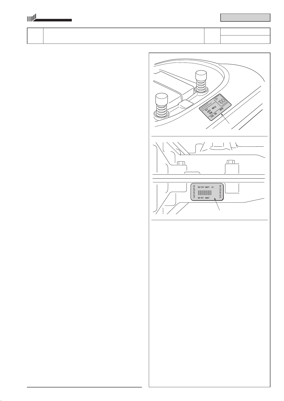
1.1 0 Identification
1.2 0 Guarantee validity
1.3 0 Service repairs after guarantee period
1.4 0 Fault notification
1.5 0 Spare parts request
1.6 0 Safety regulations
2.1 0 Level of staff training
2.2 0 Precautions while working
2.3 0 Tools
2.4 0 Slings
2.5 0 Lifting
2.6 0 Vertical positioning
2.7 0 Practical hints
3.1 1 Criteria for maintenance
3.2 0 Occasional tuning
3.3 0 Routine maintenance
4.1 0 Blades engagement adjustment
4.2 0 Blades brake adjustment
4.3 0 Brake adjustment
4.4 0 Drive belt adjustment
4.5 0 Drive pedal adjustment ( ➤hydrostatic drive models)
4.6 0 Aligning the cutting deck
4.7 0 Steering allowance adjustment
4.8 0 Steering geometry adjustment
4.9 0 Checking blades alignment
4.10 1 Sharpening and balancing of the blades
5.1 0 Removal of front hood
5.2 0 Removal of wheel cover
5.3 0 Removal of the collector channel
5.4 0 Removal of the dashboard
5.5 0 Removal of the engine
5.6 0 Removal of the rear axle
5.7 0 Removal of the cutting deck
6.1 0 Replacement of tyres and wheels
6.2 0 Replacement of front wheel bearings
6.3 0 Dismantling the steering pinion and ring gear
6.4 0 Replacement of the drive belt
6.5 0 Replacement of the small wheels for the drive belt
6.6 0 Replacement of the blades control belt
6.7 0 Replacement of the blades connection belt
6.8 0 Replacement of the blades engagement cable
6.9 0 Replacement of the supports and shafts of the blades
6.10 0 Replacement of the accelerator
6.11 0 Replacement of the brake pads and disc
7.1 0 Guide to the identification of problems in the electrical system
7.2 0 Summary table for the cutting in of the safety devices
7.3 0 Safety microswitches and switches operation check
7.4 0 Terminal board supply check
7.5 0 Carburettor solenoid valve operation check
7.6 0 Starter relay operation check
7.7 0 Electromagnetic clutch operation check ( ➤in models with electromagnetic engagement)
7.8 0 Electronic card operation check
7.9 0 Recharge circuit check
7.10 0 Care and maintenance of the sealed battery
7.11 0-1 Fitting safety microswitches
7.12 0-1 Electrical diagrams
8.1 1 Summary of tightening torques
8.3 0 Summary of main assembly sizes and checking values
8.3 0 Special tools
102 - 122
i.1- INDEX
  2 / 2
from 2000 to ••••

WORKSHOP MANUAL
page
<= ... RET ... <=
3/2003
INTRODUCTION
This manual has been compiled to help Service Centres with the maintenance, dismantling and repair of the fol-
lowing versions of the 102-122 machine:
– mechanical drive with gear box;
– hydrostatic drive (hydro).
NOTE
➤ This symbol highlights all those operations that require different working methods depending on the type of
machine, on subsequent modifications, or on the accessories fitted.
This symbol indicates an operation to be carried out with special care so as not to impair the
machine’s performance and safety.
This symbol indicates an operation to be carried out with special attention to ensure the physical
safety of the person executing the work.
This symbol indicates that a special tool should be used [see 2.3].
Descriptions of the more simple operations, which are easily carried out by a good mechanic, have been omitted,
with greater detail being given to the more specific aspects of the machine, and suggestions on the most appro-
priate methods for achieving the best repairs.
You are asked to read through this manual so that you may acquire a basic understanding of the machine, which
is necessary for working rationally, without making errors or wasting time.
Remember that problems connected with usage are fully covered in the User’s instruction handbook which, being
frequently updated, more closely coincides with the product. Finally, exploded drawings of the spare parts, which
are also periodically updated, complete the technical literature in your hands and can be of use to you for recon-
structing the entire assembly sequence.
NOTE
Each page of the manual has these indications:
– years of production of the machine concerned;
– page number and total number of pages necessary for the description of the
operation;
– indication of additional pages.
@
102 - 122
ii.1- INTRODUCTION
  1 / 1
from 2000 to ••••

WORKSHOP MANUAL
page
2 / 4
from 2000 to ••••

page
<= ... RET ... <=
102 - 122
1.1.0- IDENTIFICATION
  1 / 1
from 2000 to ••••

WORKSHOP MANUAL
page
1.1 IDENTIFICATION
a) Machine
Each machine has a label attached (1) in the battery
area which shows the technical specifications, the
model and the serial number.
The model and serial number must be shown on
each repair sheet when requests are made
under guarantee, and are indispensable for
spare part orders.
b) Transmission (Rear axle)
The transmission unit (both mechanical and hydrosta-
tic) is made up of an engine block including the rear
axle. This unit is made by another manufacturer to our
precise technical specifications which differentiate it
from similar items by this Manufacturer.
The serial number on the label (2) clearly identi-
fies the product and its specifications. This num-
ber must always be quoted when requesting
spare parts or any information from the Manu-
facturer.
c) Engine
The engine is made to precise technical specifications
which differentiate it from similar items by this Manu-
facturer.
The serial number on the label clearly identifies
the product and its specifications. This number
must always be quoted when requesting spare
parts or any information from the Manufacturer.
3/2002
2
1
<= ... RET ... <=
3/2002
1.2 GUARANTEE VALIDITY
The guarantee is supplied under the terms and the limits of the contractual relations in force. As far as the engine
and the transmission unit are concerned, the conditions given by their respective manufacturers apply.
102 - 122
1.2.0- GUARANTEE VALIDITY
  1 / 1
from 2000 to ••••

WORKSHOP MANUAL
page
<= ... RET ... <=
3/2002
1.3 SERVICE REPAIRS AFTER GUARANTEE PERIOD
The Service Centre has to make out a report containing the machine’s serial number, a summary of the problem,
the repairs carried out and any spare parts used for each repair done on the machine.
A copy of this report must be retained to be made available to the Manufacturer together with the parts in case of
any subsequent disputes with Customers.
102 - 122
1.3.0- SERVICE REPAIRS AFTER GUARANTEE
PERIOD
  1 / 1
from 2000 to ••••

WORKSHOP MANUAL
page
<= ... RET ... <=
3/2002
1.4 FAULT NOTIFICATION
The Manufacturer welcomes and finds useful the notifying of faults that recur with particular frequency. It gives the
opportunity for a careful inspection of the problem with the implementation of corrective action at production level.
At the same time the Manufacturer will notify of any faults met on the machines produced, with recommendations
for the most suitable procedures for their remedy.
102 - 122
1.4.0- FAULT NOTIFICATION
  1 / 1
from 2000 to ••••

WORKSHOP MANUAL
page
<= ... RET ... <=
3/2002
1.5 SPARE PARTS REQUEST
When requesting spare parts, the code number must be given, referring to the exploded charts for the year of
manufacture, shown on the identification label.
102 - 122
1.5.0- SPARE PARTS REQUEST
  1 / 1
from 2000 to ••••

WORKSHOP MANUAL
page
<= ... RET ... <=