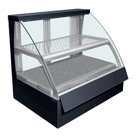
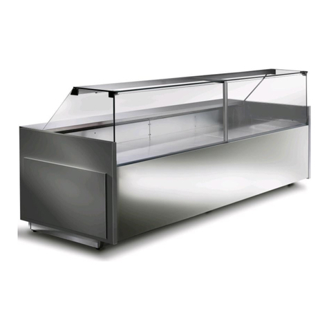
Global Refrigeration GLD52 User manual

GLD52
with R290 Refrigerant
with EVCO Control
SERVICE AND INSTALLATION
MANUAL
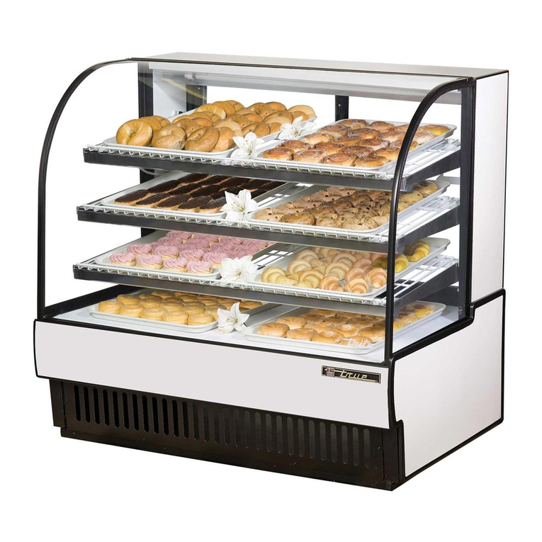
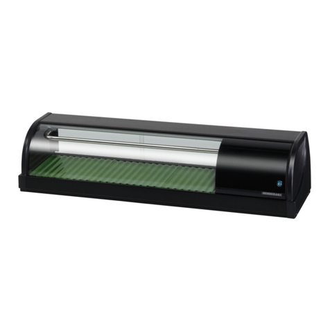
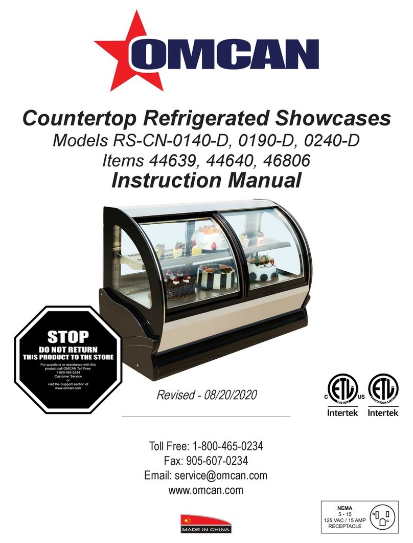
Horizontal Display Case
GLOBAL REFRIGERATION, INC
51-5882-02


ADDITIONAL INFORMATION OR TECHNICAL ASSISTANCE
For customer service or technical assistance, please call our
manufacturing facility toll free number:
1-888-650-9799
Our Customer Service Representatives and Engineers are willing to
assist you in any way possible. Office hours are from 8am to 5pm,
Monday-Friday (Eastern Standard Time)
****Copies of Installation and Maintenance Manual and for helpful videos, please visit
our web site at; www.globalref.com*****
___________________________________________________________________
Important information is contained in this manual
which should be retained in a convenient location for
future reference. Information in the manual is subject
to change without notice.


Service & Installation Model (v. 1.0) © 2020 Global Refrigeration, Inc.
2
If additional information is necessary, call the factory.
Our toll-free number is 1-888-650-9799. Technical assistance engineers are
willing to assist you in any way possible. Office hours are from 8:00 a.m. to
5:00 p.m. Monday through Friday, Eastern Standard Time.
GENERAL INFORMATION 3
An Important Message for Installers and Operators 3
HANDLING & INSTALLATION Inspecting for Damage 4
Inspecting for Shortages 4
Filing Claims 4
Handling the Cabinet 4
Removing the Skid 5
Locating the Cabinet 5
Leveling the Cabinet 5
Setting up the Cabinet 5
MODEL DESIGNATION INFORMATION & R290 Safety Warning 6
SPECIFICATIONS - DISPLAY CABINETS & R290 Safety Warning 7
DIMENSION DRAWING 8
Grounding Instructions 9
Power Supply Switch 9
Cabinet Operation-Refrigeration Mode 10
WIRING DIAGRAM –115 VOLTS 14
WIRING DIAGRAM –230 VOLTS 15
DOOR REMOVAL(Rear) 16
Aligning Doors 16
Door Gasket Removal: 16
GENERAL MAINTENANCE INFORMATION 17
Cleaning & Maintenance 17
WARNING: 17
Cleaning the Cabinet Exterior 17
Cleaning the Condenser 17
Cleaning the Storage Compartment 17 & 18
GENERAL WARNING & SERVICE WARNING for R290 REFRIGERANT 19 -21
Replacement Parts 22
COMPRESSOR –TROUBLESHOOTING CHART 23

Service & Installation Model (v. 1.0) © 2020 Global Refrigeration, Inc.
3
Thank you for purchasing this Global Refrigeration cabinet! This manual contains important
instructions for installing, using, and servicing this equipment. Read all these documents carefully
before installing or servicing your equipment. This document should be retained in a convenient
location for future reference.
GENERAL INFORMATION
An Important Message for Installers and
Operators
These instructions include information which is intended to assure the operator of correct installation, operation and
service. Before attempting installation, adjustment or maintenance, be certain of the following:
1. That you have read and fully understand the instructions.
2. That you have all tools required and are trained to use them.
3. That you have met all installation and usage restrictions and are familiar with the functions and operation
of the unit.
4. That you follow all instructions exactly as given.
All fittings, measurements, procedures and recommendations are significant. Substitutions and approximations must be
avoided. Improper handling, maintenance, installation and adjustment, or service attempted by anyone other than a
qualified technician, may void the future warranty claims and cause damage to the unit and/or result in injury to the
operator and/or bystanders.
Record for Service______________________
Model No.____________________________
Serial No. _____________________________
Invoice Date___________________________
Start-up Date__________________________
Telephone for Service___________________
BE SURE TO INSPECT CABINET FOR SHIPPING DAMAGE BEFORE AND AFTER UNCRATING IT.

Service & Installation Model (v. 1.0) © 2020 Global Refrigeration, Inc.
4
HANDLING & INSTALLATION
Inspecting for Damage
NOTE: The transportation company or other parties involved in the shipment are responsible for loss and/or damage.
When direct delivery was made by the transportation company, follow the procedure as outlined in the following
steps: Always inspect before and after uncrating. Inspect the uncrated unit(s) before locating (preferably at the
point of unloading by the transportation company.) You may leave the skid on the unit for ease of locating it later.
a) Damaged cartons or containers - If these are damaged in any way, open them and inspect the contents
in the driver’s presence.
b) Have the driver note the nature and extent of the damage on the freight bill.
c) Notify the transportation company’s office to request an inspection. Carrier claim policies usually require
inspections to be made within 15 days of delivery.
d) Always use care when removing shipping tape, blocks, pads, hardware, or other materials. Retain all
crate and packaging material until you are satisfied that the unit is completely operational.
e) Contact factory if technical assistance is required.
f) If damage is noticed (whether before or after uncrating the unit) the following claim procedure must be
completed.
Inspecting for Shortages
NOTE: Refer to the “Inspecting for Damage” instructions and follow the procedure described.
a) Check the number of cartons and/or containers delivered with the quantity shown on your receipt.
b) If the quantities are not the same, have the driver note the shortage and file your claim accordingly.
Filing Claims
a) File a claim for loss or damage at once with the transportation company for:
1. A cash adjustment
2. Repairs
3. Replacement
b) When filing your claim, retain all packaging materials and receipts.
Handling the Cabinet
The refrigeration system of the cabinet is designed to operate with the cabinet located on a flat surface. Avoid
tilting the cabinet more than 30° to any side. If the cabinet must be tilted on an angle for handling or moving
purposes, allow it to sit in an upright position 20 to 30 minutes prior to plugging it in and starting the cooling of the
storage compartment. DO NOT DRILL HOLES IN THE CABINET WALLS. THIS WILL VOID THE WARRANTY.
Service & Installation Model (v. 1.0) © 2020 Global Refrigeration, Inc.
5
Removing the Skid
Remove the front and rear covers. Remove the four (4) bolts securing the cabinet to the skid. Carefully slide the
cabinet off the skid onto the floor.
Locating the Cabinet
This model is a display cabinet and should be positioned to expose the illuminated displays to customers in the
store and provide a clear space behind for the person serving.
Select a location where you are sure that the cabinet won’t be exposed to heat sources such as sun through a
window, store heating or cooling ducts, exhausts from other cabinets, etc. Make sure there is adequate space on
the serving side for loading cabinet and serving efficiently. The following must also be observed in order to
properly locate the cabinet:
a) The cabinet must be installed on a sturdy and solid, level floor.
b) The cabinet should be installed in a protected, dry, and well-ventilated area, away from any heat source.
c) The cabinet is designed to be installed in an environment where the temperature is at or below 75F and
the relative humidity is 55% or less.
d) The front, back and top of the cabinet must be open for compliance with safety and sanitation standards.
The sides require no clearance. Blocking the airflow to the condensing unit will adversely affect the
performance and will potentially void the warranty.
Leveling the Cabinet
Level the cabinet using a spirit level on top. Level front to back and side to side to assure quiet operation and
satisfactory door and drain operation. Shim under the cabinet base as necessary to assure a level cabinet. To meet
NSF requirements, these cabinets must be sealed to the floor with an NSF listed or FDA approved sealant.
Setting up the Cabinet
Cabinets are shipped with the pilasters in place. Shelving is also supplied with the cabinet.
Shipping material (cardboard, paper, plastic, ties, etc.) should be removed from shelving and the product area.

Service & Installation Model (v. 1.0) © 2020 Global Refrigeration, Inc.
6
MODEL DESIGNATION INFORMATION
115V, 60HZ
PART #
MODEL #
DATA PLATE
STYLE
52-2900-*
GLD52
GLD52
LOW TEMP, CURVED FRONT GLASS
EXPORT 220V, 50HZ
PART #
MODEL #
DATA PLATE
STYLE
52-2900-*
EGLD52
EGLD52
LOW TEMP, CURVED FRONT GLASS
EXPORT 220V, 60HZ
PART #
MODEL #
DATA PLATE
STYLE
52-2900-*
KGLD52
KGLD52
LOW TEMP, CURVED FRONT GLASS
Important information is contained in this manual which should be retained in a convenient location for future
reference. Information in this manual is subject to change without notice.
Manual effective for models produced after November 2022.
.

Service & Installation Model (v. 1.0) © 2020 Global Refrigeration, Inc.
7
SPECIFICATIONS - DISPLAY
CABINETS
MED TEMP
LOW TEMP
Temperature Range
Coming Soon
0°F to -15°F
Insulation
Coming Soon
2 5⁄16" Foam in Place
Compressor Size
Coming Soon
SCE21CNLX
(16-0510-00
Condenser Type
Coming Soon
Fin & Tube
Evaporator Type
Coming Soon
Fin & Tube
Refrigerant Type
Coming Soon
R290 (Flammable Refrigerant)
Defrost System
Coming Soon
Timed, Hot Gas
Electrical Specs.
Coming Soon
115/60/1
Sanitation
Coming Soon
UL EPH to NSF 7
Shelves
Coming Soon
Wire, Epoxy Coated; or Glass w/ ss frame
UL & CSA Listing
Coming Soon
Yes

Service & Installation Model (v. 1.0) © 2020 Global Refrigeration, Inc.
8
DIMENSIONS

Service & Installation Model (v. 1.0) © 2020 Global Refrigeration, Inc.
9
Grounding Instructions
This appliance is equipped with a three-prong (grounding) plug for your protection against shock
hazards. This appliance should be plugged directly into a properly grounded three prong receptacle.
Where a two-prong wall receptacle is encountered, it must be replaced with a properly grounded
three-prong receptacle in accordance with the National Electrical Code and local codes and
ordinances. The work must be done by a licensed electrician (cabinet should be on a dedicated
circuit unto itself. Refer to serial data for correct circuit ampacity).
(USA) 120 VOLTS
Power Supply Switch
NOTE: When servicing or cleaning supply power must be turned off. The power supply switch is located at the rear of
each cabinet behind the lower rear grill. The switch is incorporated into the electrical box assembly.
The light switch is located at the rear of each cabinet behind the lower rear grill. The switch is incorporated into the
electrical box assembly.
These cabinets utilize a microprocessor control to manage both cavity temperature and defrost functions.

Service & Installation Model (v. 1.0) © 2020 Global Refrigeration, Inc.
10
Cabinet Operation-Refrigeration Mode
Upon setting the cabinet in its final location, turn power supply on. The cabinet display should be indicating the
cabinet temperature. There is a three minute time delay sequence built in each time the supply power is lost
(compressor circuit). Evaporator fan starts and lights come on (medium temp models). Three minutes later the
compressor starts. On low temp models the evaporator fan delays until the evaporator coil reaches 28°F.
The EVCO DIGITAL CONTROL located behind the lower front grill panel has several functions:
Display cabinet temperature
Change cavity set point temperature
NOTE: ON MED TEMP CABINETS DO NOT SET BELOW 33°F.

Service & Installation Model (v. 1.0) © 2020 Global Refrigeration, Inc.
11

Service & Installation Model (v. 1.0) © 2020 Global Refrigeration, Inc.
12
IMPORTANT!!! –THIS PAGE INTENTIONLY LEFT BLANK

Service & Installation Model (v. 1.0) © 2020 Global Refrigeration, Inc.
13
IMPORTANT!!! –THIS PAGE INTENTIONLY LEFT BLANK

Service & Installation Model (v. 1.0) © 2020 Global Refrigeration, Inc.
14
WIRING DIAGRAM –115 VOLTS (USA ONLY)
IMPORTANT!!! –THIS WIRING DIAGRAM 00-3324-00 IS FOR EVCO CONTROL

Service & Installation Model (v. 1.0) © 2020 Global Refrigeration, Inc.
15
WIRING DIAGRAM –230 VOLTS (EXPORT ONLY)
IMPORTANT!!! –THIS PAGE INTENTIONLY LEFT BLANK

Service & Installation Model (v. 1.0) © 2020 Global Refrigeration, Inc.
16
DOOR REMOVAL(Rear)
Aligning Doors
Proper alignment of the cabinet doors will eliminate
hinge binding and provide correct gasket seal.
1. Check cabinet level and door alignment by firmly
closing each door. Observe the movement of the
other doors. They should open slightly, then
close and seal.
2. The hinge has slotted mounting holes for
adjustment.
3. Additional adjustment can be made by adding
shims between the hinge wing and either the
door or the cabinet face.
Door Gasket Removal:
Allow door to warm up to room temperature. At one corner simply pull the gasket out of the plastic groove
provided. Replace new gasket by firmly pressing the rear dart of gasket into the plastic groove all the way around
the door.

Service & Installation Model (v. 1.0) © 2020 Global Refrigeration, Inc.
17
GENERAL MAINTENANCE
INFORMATION
Cleaning & Maintenance
WARNING:
To avoid the possibility of an electrical shock, turn OFF Master Supply Switch and unplug the electric cord of
the cabinet before cleaning or touching electrical connections or parts.
Cleaning the Cabinet Exterior
Wipe the exterior with a cloth dampened in mild detergent water; rinse and wipe dry with a soft, dry cloth. Do not use
abrasive or caustic cleaners or scouring pads.
Cleaning the Condenser
Periodic cleaning of the condenser can be easily accomplished by brushing the coils with a soft brush and/or using
a vacuum cleaner with a brush attachment.
Be sure that dirt, dust and collection of other debris does not build up to a point air circulation through the
condenser is restricted.
Cleaning the Storage Compartment
Remove the product and store it in another suitable cabinet, if possible. Be sure to prevent spoilage of the product
which may occur if it is left a room temperature.
Turn OFF the Master Supply Switch and unplug the cabinet.
Remove the shelving.
Wash the inside surface of the doors and the entire interior storage area with warm water and baking soda
solution per quart of water. Rinse thoroughly with clean water and wipe dry. This procedure can also be used for
cleaning the door gaskets.
IMPORTANT:
Do not use any objects or cleaners which may leave residues, odors, or particles. Avoid the use of
Table of contents