Global 261121 User manual

031811
OWNER’S MANUAL
IMPORTANT: READ OWNER’S MANUAL CAREFULLY
Please fill out and return your warranty card
MODEL 261121
Floor Burnisher with
Dust Control

CONGRATULATIONS on your purchase of a Global
product. We appreciate your business and will do
everything in our power to keep you happy with your
purchase for many years to come.
Your purchase entitles you to the best protection by
one of the most comprehensive warranties in the
industry.
Thank you for purchasing a GLOBAL product.
TABLE OF CONTENTS
Safety Precautions 3
Machine Operation 4
Machine Maintenance & Storage 4
Parts Lists 5-9
Wiring Diagram 10
TABLE OF CONTENTS
2
globalindustrial.com
ORDER YOUR CLEANING CHEMICALS & PADS
Visit
www.globalindustrial.com
Or Call 1-800-645-1232
CLEANING CHEMICALS
Floor Finish
Model 640403
(Case of 4)
PADS (Case of 5)
High Freq., Soft to
Medium Finish -
Model 261166
Low Freq., Medium
to Hard Finish -
Model 261167
Low Freq., Hard Finish -
Model 261168

This machine must be grounded! Grounding provides
the path of least resistance for electrical current. To
reduce the risk of electrical shock should the machine
malfunction, the machine has a special grounding
plug.
This machine is intended for commercial use. It is
constructed for use in an indoor environment and is
not intended for any other use.
• Use with approved accessories only
•
Use with non-approved accessories voids warranty
• DO NOT modify machine
• Modification to machine voids warranty
All operators shall read, understand and exercise the
following safety precautions:
1) Do not operate machine:
• Unless trained and authorized.
• Unless you have read and understood
operators manual.
• In flammable or explosive areas.
• With damaged cord or plug.
• If not in proper operating condition.
• In outdoor areas.
• In standing water.
• Without bag / filters in place.
• With the use of extension cords.
2) Before operating machine:
• Make sure all safety devices are in place and
operating properly.
3) When using machine:
• Use only approved burnishing pads
• Do not run machine over cord.
• Do not pull machine by cord or plug.
• Do not pull cord around sharp edges or corners.
• Ensure the dust collection bag is in place and is
tightly sealed to the machine.
• Turn power switch to “off” prior to unplugging
machine.
• Do not unplug by pulling on the cord.
• Do not stretch cord.
• Do not handle plug with wet hands.
• Keep cord away from heated surfaces.
• Do not pick up burning or smoking debris such
as cigarettes, matches or hot ashes.
• Report any damages to your supervisor.
• DO NOT attempt to fix machine by yourself. All
repairs must be made by authorized
technicians.
4) Before leaving or servicing machine:
• Turn off machine.
• Unplug cord from outlet.
5) When servicing machine:
• Unplug cord from outlet.
• Use manufacturer supplied or approved
replacement parts.
• Any lifting or hoisting of machine should be
done with OSHA approved equipment and
safety precautions.
SAFETY PRECAUTIONS
3
Do not remove the ground pin under
any circumstances!
WARNING
!

OPERATION OF HIGH SPEED FLOOR MACHINE
4
READ OPERATORS MANUAL
THOROUGHLY PRIOR TO
OPERATING OR SERVICING
THIS MACHINE
GENERAL USE
1. Remove any obstructions or other obstacles in the area
which is to be cleaned.
2. Remove dust recovery bag and empty it out in a trash
receptacle. Replace dust recovery bag on machine,
ensuring it is sealed tightly to the machine.
3. Place the handle in the upright position and tilt machine
back until handle rests on the floor.
4. Remove the pad center gripping device by unscrewing
the thumbscrews.
5. Place an approved burnishing pad on the pad driver
and re-attach the center gripping device. (check with
Global Equipment (1-800-645-1232) for approved
pads).
6. Place machine back into its upright position.
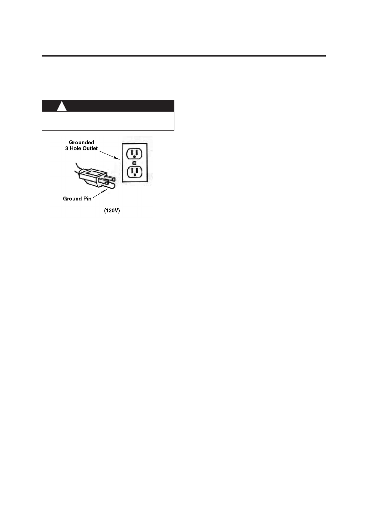
7. Plug power cord into grounded outlet.
8. The handle height may be adjusted by lifting up on the
handle release lever, located on the right side of the
switch housing. Pull trigger and lower handle to desired
operating position. Release trigger to lock handle into
place.
9. To start the machine, push on the red safety release
button located on the top of the switch housing and
squeeze either switch lever.
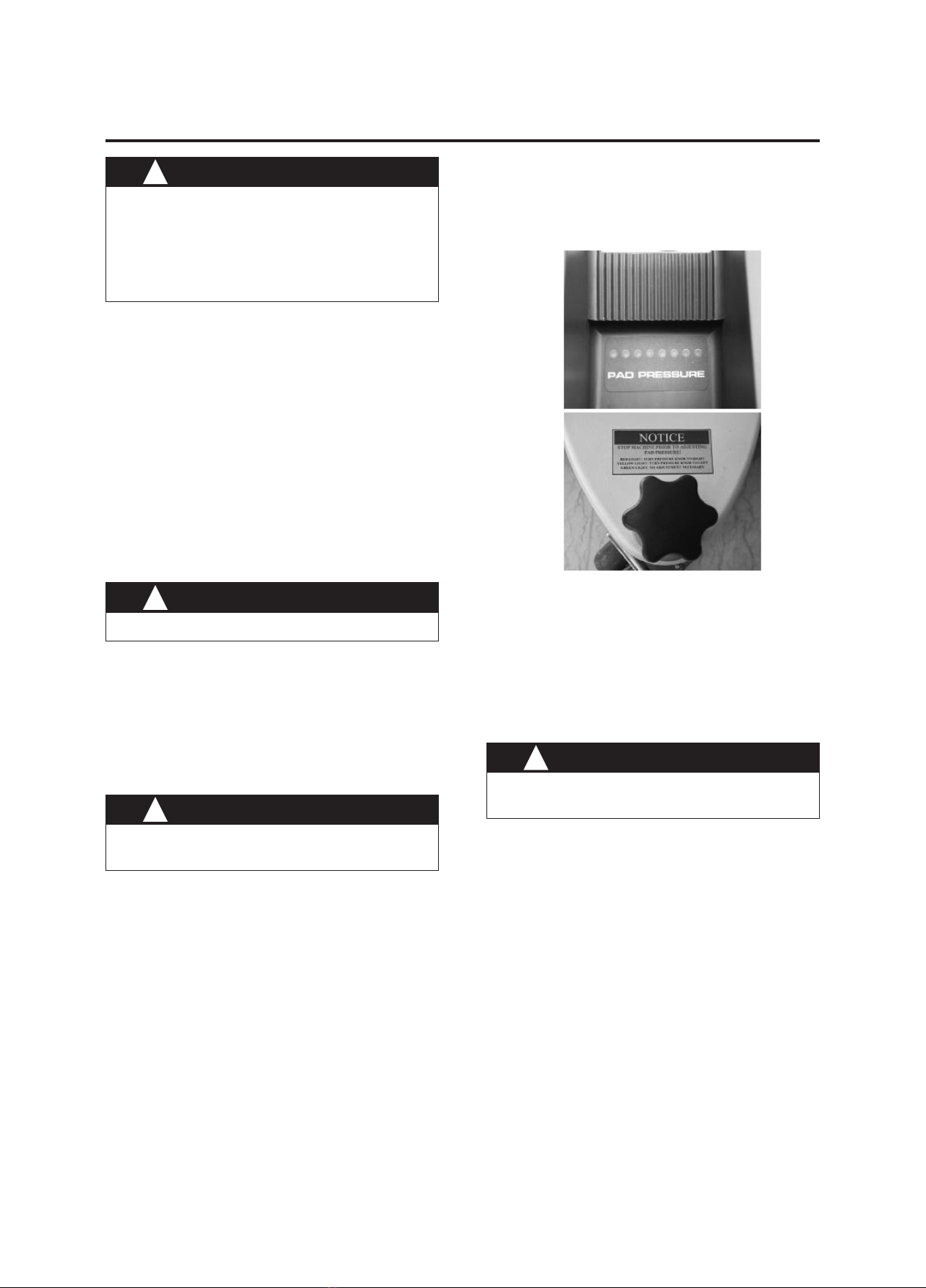
10. Once the machine has reached operating speed, look
at the digital pad pressure meter located on the top of
the motor cover. There are 3 light colors which will help
you determine optimal pad pressure for operating the
machine. RED LIGHT(S): If one or both red lights are
illuminated, stop the machine and turn the pad
pressure adjustment knob to the right to reduce pad
pressure. YELLOW LIGHT(S): If one or both yellow
lights is illuminated, stop the machine and turn the pad
pressure adjustment knob to the left to increase the
amount of pad pressure. GREEN LIGHT(S): If one, two
or three green lights are illuminated, the machine is
running at the optimal pad pressure and you may begin
working.
11. When the machine is in operation, both hands should
be gripping on the handle.
12. To stop the machine at any time, simply release the
switch lever, and the machine will stop automatically.
MAINTENANCE
To keep the machine performing well for many years,
please follow the following maintenance procedures.
1. Unplug machine as soon as you are done using it.
2. Remove dust recovery bag and empty contents into a
trash receptacle. Inspect dust recovery bag for any
damage prior to replacing it on the machine.
3. Clean the outside of the machine with a mild cleaner.
4. Check power cord for any damage. If damage is
detected, replace power cord immediately.
5. Lubricate wheels with a water resistant lubricant once a
month.
6. Check machine for loose or missing nuts and bolts, and
replace as necessary.
7. If the machine is used in a dusty environment, you may
remove the motor cover and blow the motor clean with
compressed air. This will ensure proper ventilation, and
allow the motor to run cooler.
STORAGE
1. Unplug machine from power source and wrap cord on
handle.
2. Store machine in upright position and in a dry area.
WARNING
Be sure the machine is not plugged into an outlet.
!
WARNING
Never use an extension cord in
conjunction with the standard power cord.
!
WARNING
Always confirm that the machine is unplugged
prior to performing any maintenance or repairs.
!
CAUTION
THIS IS A SPECIALIZED MACHINE
WHICH REQUIRES THE OPERATOR TO
UTILIZE AN APPROVED PAD, AND
MUST BE ADJUSTED PROPERLY TO
ENSURE THE HIGHEST POSSIBLE
PERFORMANCE AND PRODUCTIVITY.
!

MODEL 261121 - BASE ASSEMBLY
5
PARTS LIST

DIA No. Part Number Description NO Req'd
1 VF52114 PLASTIC STAND, RIGHT 1
2 VF52115 PLASTIC STAND, LEFT 1
3 VF54048 CONNECTOR, MOTOR COVER 1
4 VV20509 SCREW, M5x10, PH 16
5 VF54017 LABEL 2
6 VF54047 COVER, MOTOR 1
7 VF13503 NUT, NYLON INSERT, M8 3
8 VF13524 WASHER, PLAIN 3
9 VF54020 RIGHT ARM 1
10 VF54019 LEFT ARM 1
11 GT13016 SCREW, M8x60, HEX SOCKET 3
12 VA13480 SCREW, M8x40, HEX SOCKET 4
13 VF13519 WASHER, LOCK, 8 5
14 VF54009 BUSHING 2
15 VF14007 HEX SCREW, M10x32 2
16 VF54010 ADJUSTMENT SCREW 1
17 VF14078 SCREW, M3x10, PH 4
18 ZW42540A LED DISPLAY PANEL 1
19 VF54046 RISING SCREW 4
20 VF54004 WHEEL BRACKET 1
21 VF50119 WAVE WASHER, 12 4
22 VF52017 WHEEL, 5" 4
23 VF13666 WASHER, PLAIN,12 4
24 VF44012 SCREW, M5x12.7 4
25 VF54005 RETAINER PLATE, AXLE 2
26 VV13621 SCREW, ST5x20 6
27 VA13474 SCREW, M5x16, PH 2
28 VF13474A WASHER, PLAIN, 5x16 4
29 VF54015 BUMPER 1
30 VA14010 SCREW, M5x20, PH 2
31 VF54016 CLAMP, SKIRT 1
32 VF13517 WASHER, PLAIN, 10 6
33 VF13518 WASHER, LOCK, 10 6
34 GT13097 HEX SCREW, 3/8"-16x1.25" 4
35 VF52008 SPACER 1
36 VF99024 PAD HOLDER, 20" 1
37 VF52021 WASHER, PLAIN 1
38 GT13018 HEX SCREW, M8x30 1
MODEL 261121 - BASE ASSEMBLY
6

DIA No. Part Number Description NO Req'd
39 VF54027 LOCK WASHER, BIG MOUTH 1
40 VF99003A BIG MOUTH 1
41 VF54006 FLEXIBLE SKIRT 1
42 VF54011 CASTER, DUAL SWIVEL 1
43 VF54028 SCREW BUSHING, HOUSING 1
44 VF54001A HOUSING 1
45 VF54032 ADJUSTMENT DECAL 1
46 VF54036 HOOK, COVER, DUST BAG 1
47 VF50108 NUT 1
48 VF14081 NUT, M12 1
49 VF50103A ADJUSTING KNOB, CASTER 1
50 VF54021 SPACER 2
51 ZD40205 KEY, MOTOR SHAFT 1
52 VF54007 ELBOW ADAPTOR 1
53 VF13022 SCREW, M4x12, PH 2
54 VF54003 DUST COLLECTOR BAG 1
55 ZD40B MOTOR, 120V 1
56 VF52022 THERMAL CONDUCTION GASKET 1
57 VF44204 RECTIFIER 1
58 VF52023 COVER, RECTIFIER 1
59 VF54040 RISER, ARM 2
60 GT13032 WASHER, PLAIN, 6x16 1
61 VF14232 HEX SCREW, M6x10 1
62 VF54008 PIVOT BLOCK, ADJUSTOR 1
63 VF54014 COVER, DUST BAG 1
64 VF13544 SCREW, ST4x10 4
65 VF47035A LOGO 1
MODEL 261121 - BASE ASSEMBLY
7

MODEL 261121 - HANDLE ASSEMBLY
8
PARTS LIST

DIA No. Part Number Description NO Req'd
1 VF47009 FRONT COVER, GEAR SEAT 1
2 VF54037 GEAR SEAT 1
3 VF40171 GEAR & LEVELING INSERT KIT 1
4 GV40227 WASHER, NYLON 2
5 GV40228 "O" RING, GEAR SEAT 2
6 VF50120 GROMMET 2
7 VF47015 REAR COVER, GEAR SEAT 1
8 VF14080 SELF-TAPPING SCREW, ST4x25 2
9 VF14087 SELF-TAPPING SCREW, ST4x35 2
10 VF47046 SEAL RING 1
11 VF47045A HOOK, CABLE 1
12 VF13616 SCREW, HEX SOCKET, M10x55 1
13 GT13019 HEX SCREW, M6x40 4
14 VF40171 GEAR & LEVELING INSERT KIT 1
15 GT13013 NUT, M4 4
16 VF47103 LEVELING ROD 1
17 VF47007 SPRING, LEVELING 1
18 VF47033 RETAINER 1
19 VF47008 SEAL, TUBE 1
20 VF47102 TUBE 1
21 VA13474 SCREW, M5x16, PH 1
22 VA13476 SCREW, M5x40, PH 1
23 VF45119 CORD, POWER SUPPLY, STOW 14/3C 1
24 VF14212 SCREW, M3x25, PH 2
25 VF13511 WASHER, LOCK, INTERNAL TOOTH 2
26 VF44203 SWITCH ASSY, 20A, 250V 1
27 VF45124 JUMP WIRE 1
28 VV13650 SCREW, M4x10, PH 2
29 VF48309 BLOCK, HANDLE CABLE 1
30 VF46703 OPERATING TRIGGER, LEFT 1
31 AS22009 STRAIN RELIEF, CORD 1
32 VF52019 COVER, SOLUTION LEVER 1
33 VF14226 SCREW, FH, M6X35 2
34 VF52118 REAR COVER, SWITCH HOUSING 1
35 VF54029 DECAL, NOTICE 1
36 VF14218 SCREW, M6x40, PH 2
37 VF46705 SAFETY BLOCK 1
38 GV40218 SPRING, SAFETY BLOCK 1
39 VF99010C CIRCUIT BREAKER, 17A 1
40 VF13527 EXTERNAL TOOTH, WASHER, 4 1
41 VF13526 SCREW, HOLDING, M4x30 1
42 VF46704 OPERATING TRIGGER, RIGHT 1
43 VF48306 PIN, LEVER 3
44 GT13014 NUT, M4, NYLON INSERT 1
45 VF46707 TRIGGER, HANDLE ADJUSTMENT 1
46 GT13017 BIG WASHER, PLAIN, 4x16 1
47 VF46706 HANDLE GRIP 2
48 VF46701 FRONT COVER, SWITCH HOUSING 1
49 VF47035A LOGO 1
50 VF13600 WASHER, PLAIN, 4
51 VF13502 NUT, NYLON INSERT, M6 4
52 VF45120 CABLE, HANDLE, SJTW 14/3C 1
MODEL 261121 - HANDLE ASSEMBLY
9

MODEL 261121 - WIRING DIAGRAM
10
Table of contents
Other Global Floor Machine manuals
Popular Floor Machine manuals by other brands

Nilfisk-Advance
Nilfisk-Advance SD 130 Instructions for use

Windsor
Windsor EPB2 owner's guide

Premiere Products
Premiere Products SV 380 MD operating instructions

R.P.S. Corporation
R.P.S. Corporation XR 2010 Operator's manual

Victor
Victor MR 60B Use and maintenance manual

Diamond Products
Diamond Products F1500 Operator's manual