globalwater FC220 User manual

Global Water
800-876-1172 •globalw.com
1
Global Water
Instrumentation, Inc.
151 Graham Road
P.O. Box 9010
College Station, TX 77842-9010
T: 800-876-1172
Int’l: (979) 690-5560, Fax: (979) 690-0440
E-mail : globalw@globalw.com
FC220/PC320 Data Logger Option
02-087
Publication Number 38870512

Global Water
800-876-1172 •globalw.com
2
Congratulations on your purchase of a Global Water FC220 Flow
Monitor or PC320 Process Controller with Internal Data Logger Option.
This instrument has been quality tested and approved for providing
accurate and reliable measurements. We are confident that you will find
the product to be a valuable asset for your application. Should you
require assistance, our technical staff will be happy to help.
Table of Contents
I. FC220/PC320 Data Logger Option •••Page 3
II. Scaling the 4-20mA Output ••••4
III. Calibrating the Data Logger Option •••5
IV. Historical Record ••••••7
V. Determining Relay States ••••8
VI. Excel Macro ••••••9
VII. Technical Support ••••••10
Copyright Global Water Instrumentation, Inc. 2012

Global Water
800-876-1172 •globalw.com
3
I. FC220/PC320 Data Logger Option
The FC220 Flow Monitor and PC320 Process Controller have a scalable 4-20mA
output that can be used to monitor and record the sensor output values. They also
have 4 relays for controlling external devices like water samplers, pumps, alarms,
etc. These two products also have provision for a factory installed internal data
logger option that can record the 4-20mA output on the logger’s channel one input.
The logger’s channel 2 input is used to record an analog voltage that represents the
current state of all 4 relays. Free software supplied with the logger option will
convert this analog voltage to the relay states for real-time viewing and download
to spreadsheets.
The logger option functions the same as all other Global Water loggers. A sample
interval is programmed into the logger that will record the sensor data at regular
programmable intervals. In addition; the data logger option also records the
current state of all 4 relays whenever any of them change state, giving a time stamp
to these relay events with a one second resolution. There are three possible relay
states; On, Off and Pulse. ON and Off are steady states, the pulse state represents a
relay turning on for one second before turning off again.
When the Global Logger II software with version 2.1.8 or greater is connected to
the FC220/PC320 Data Logger Option, the following screen appears. The version
number is shown at the top right corner, or by selecting Help from the toolbar, then
About.

Global Water
800-876-1172 •globalw.com
4
This screen differs from the screen shown when connecting to other Global Water
logger products by the 4 fields at the right side of the main screen. By placing the
software in Sample Continuously mode, these 4 fields show the current state of all
4 relays in real time. The relay states are also recorded into the historical record
for download and analysis in a spreadsheet program such as Excel.
II. Scaling the 4-20mA Output
Before the data logger option can be fully calibrated, the 4-20mA output of the
FC220 Flow Monitor or PC320 process Controller must be scaled to a particular
range. By pressing the MENU button for 2 seconds, the menu display is show.
Press the MENU key until the 4-20mA Output Calibration menu shown below is
displayed.
To scale and calibrate the 4-20mA output press the RIGHT arrow key. The 4mA
Set Point is the flow or sensor value that results in an output current of 4mA. Use
the LEFT and RIGHT arrow buttons to select a digit, then use the UP and DOWN
arrow buttons to scroll through the number 1-9 and decimal point. In this way, set
the 4mA Set Point to the desired value. If appropriate, use the same process to set
the units as described in the FC220 or PC320 manual. Press SAVE to store these
settings and MENU to move forward. The 20mA Set Point is the flow rate or
sensor value that corresponds to a 20mA output current. Use the arrow buttons to
change the 20mA Set Point value. Press SAVE to store this setting. Any flow rate
or sensor reading between these two set points will be scaled to the corresponding
output current. The next three menus are generally set at the factory and should
not need to be changed. The 4mA Output Cal menu allows the 4-20mA output to
be set to exactly 4mA. Connect a DC current meter between the 4-20mA output
and ground. Use the UP and DOWN arrows to raise and lower the raw data
number (and output current) until the current meter reads as close as possible to
4.000mA. Press SAVE and MENU. The 20mA Output Cal menu sets the 20mA
output in the same way. Use UP and DOWN to adjust the output until the current
meter reads 20.000mA. The Calibrate Logger menu is used to calibrate channel
two of the data logger option.

Global Water
800-876-1172 •globalw.com
5
III. Calibrating the Data Logger Option
Connect the computer to the USB port on the FC220 or PC320 data logger.
Launch the Global Logger II software and connect to the logger, you must use
Global Logger II version 2.1.8 or higher. Click the Setup button to enter the
calibration screens. A few settings are required for the logger option to operate
properly, these are shown below. In the General tab; set the Sensor Warm-Up
Time to zero seconds and enable Sample-On-Demand by checking the checkbox.
The logger will not record relay events unless the Sample On Demand function is
enabled.
Select the Analog Channels tab.

Global Water
800-876-1172 •globalw.com
6
Before proceeding, make sure that the FC220 or PC320 4-20mA Output
Calibration process has already been completed as described in the previous
section. On the FC220 or PC320, enter the setup menus and scroll down to the
output calibration menu. Note that within 1 minute of the last button press, the
FC220 and PC320 will automatically exit the setup menus. If this happens during
the calibration process, return to the setup menu.
Calibrating Channel One
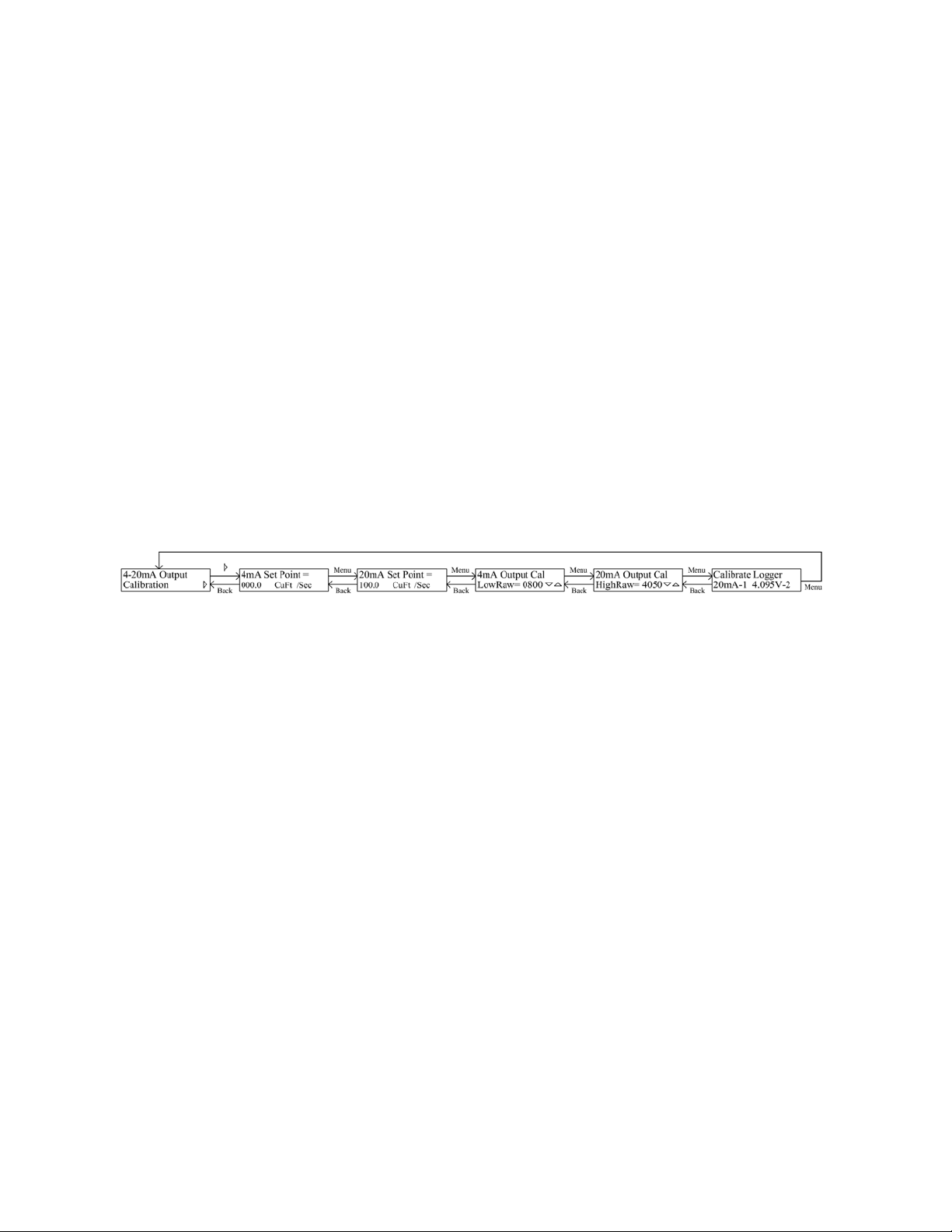
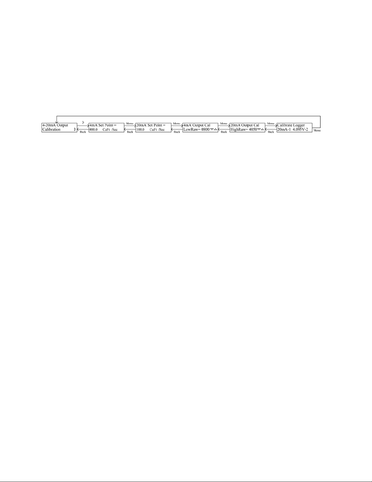
Enter the sub-menus and note the 4mA and 20mA Setpoints. Using the MENU
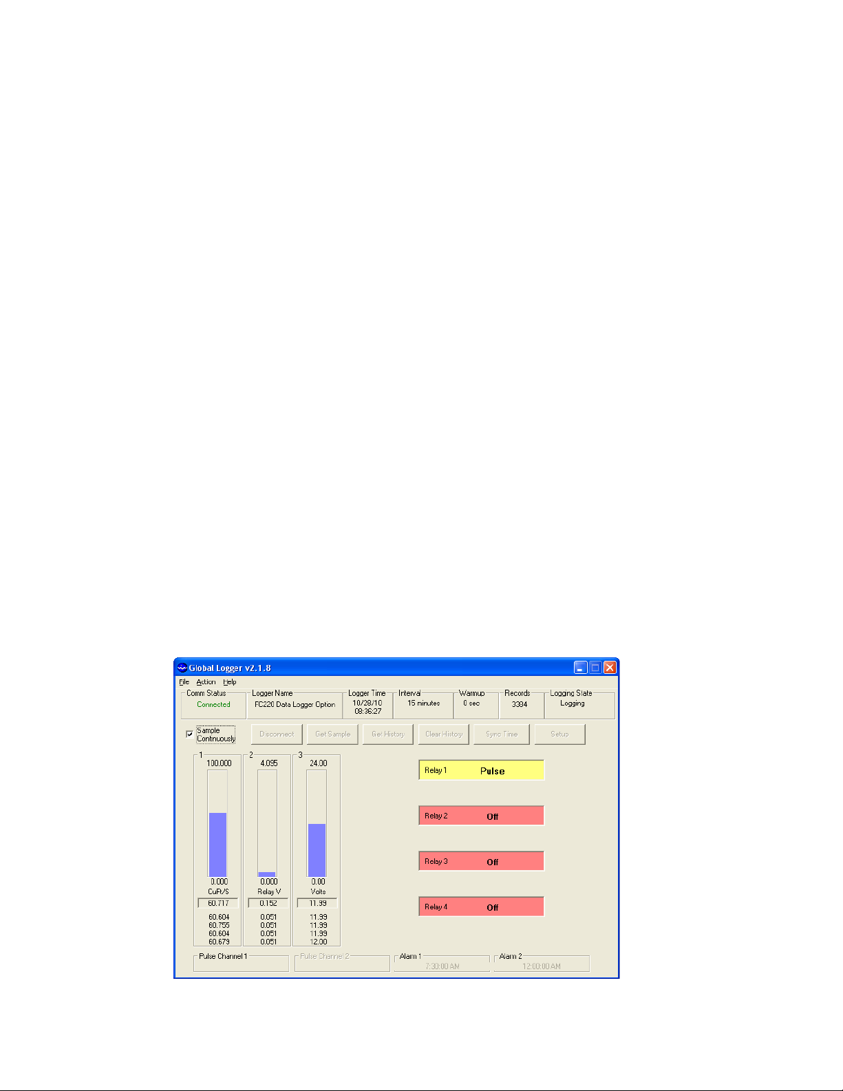
button, advance to the 20mA Output Cal menu. From the Global Logger II
software, click the Calibrate button at the bottom of the Channel 1 field in the
Analog Channels tab. In the first of four calibration screens, enter the value of the
20mA Set Point programmed into the FC220 or PC320, then click Next. When the
value has settled, click Next again. On the FC220 or PC320, press the BACK
button to return to the 4mA Output Cal menu. In the Channel 1 Calibrate screen of
Global Logger II, Enter the value of the 4mA Set Point programmed into the
FC220 or PC320, then click Next. When the value has settled, click Next. Enter
the engineering units into the Units field that correspond to the units used in the
4mA and 20mA Set Points in the FC220 or PC320. The Display High Value and
Low Value fields are used to set the range of the bar graph of the main display only,
they are not part of the calibration process. Enter values to scale the bar graph to
the desired range.
Calibrating Channel 2
On the FC220 or PC320, advance to the “Calibrate Logger 20mA-1 4.095V-2”
menu. In the Analog Channels setup menu of Global Logger II, click the Calibrate
button for channel 2. For the High Engineering Value, enter 4.095 and click next.
When the value has settled, click Next again. Enter zero into the Low Engineering
Value, then click Next. Click Next one more time to exit the calibration menus.
Click on the Low Raw Value box and enter zero. In the Display High Value box,
enter 4.095. In the Display Low Value, enter zero. For the Channel 2 Units, enter
Volts. Select the desired number of decimal places for channel 1, select 3 decimal
places for channel 2. Click the Program Settings button to program the logger.
Click the Back to Main Window button to return to the main screen. The
calibration process is complete.

Global Water
800-876-1172 •globalw.com
7
IV. Historical Record
To view the historical record in the data logger, click the Get History button.
The historical record shows the data recorded at the normal sample intervals
programmed into the logger; in the above case, at 1 minute intervals. The data at
the normal logging intervals will show the voltage as zero and the relay states as
undefined, or ---. In addition to these records, the changing states of all 4 relays
are also recorded. These records will not interrupt the normal logging interval of
the logger. In the record shown above, the FC220 Flow Monitor is programmed to
output a pulse on relay 1 for every 20,000 cubic feet of water. At an average flow
rate of 60.6 cubic feet per second, relay 1 will pulse about every 5-1/2 minutes as
shown in the historical data. In this example, relays 2-4 are disabled. For the
PC320 Process Controller, the record will indicate pulse events, as well as the time
when any or the relays turned on or off in a steady state mode.

Global Water
800-876-1172 •globalw.com
8
V. Determining Relay States
The changing states of the relays are recorded as an analog voltage, generally on
channel 2. The voltage represents the state the relay was changed to at that time;
according to the equation:
Voltage in Volts = (50 + 50*S1 + 150*S2 + 450*S3 + 1350*S4) / 1000
Where S1 is the state of Relay1, S2 for Relay 2 ...
Off State, S =0
On State, S = 1
Pulse State, S = 2
Thus a voltage between 0.050 and 4.050 Volts represents the states of all 4 relays.
The 4 relays have 81 possible combinations of states. The voltage is first
converted to an integer from 0-80 using this equation:
StateValue = INTEGER ((Voltage + 0.025) / 0.05) – 1
In base 3 this number 0-80 is in the range of 0000 to 2222. The most significant
digit is the state of relay 4, the least is the state of relay 1;
0 = Off
1 = On
2 = Pulse
These states are separated using these equations:
Relay 1 State = MODULUS (StateValue / 3)
Relay 2 State = MODULUS ( INTEGER (StateValue / 3), 3)
Relay 3 State = MODULUS ( INTEGER (StateValue / 9), 3)
Relay 4 State = INTEGER (StateValue / 27)

Global Water
800-876-1172 •globalw.com
9
VI. Excel Macro
This Visual Basic macro can be used in an Excel spreadsheet to extract the relay
state information from the recorded analog voltage:
Function RelayStatus(RelayVoltage As Double, RelayNumber As Integer) As String
Dim Alpha As String
Application.Volatile
On Error GoTo FixError
' Convert relay voltage to integer from 0-80, in base 3 this value represents the state of all 4 relays
' Most significant digit is relay 4, least is relay 1
' 0 = Off, 1 = On, 2 = Pulse
RelayVoltage = Int((RelayVoltage + 0.025) / 0.05) - 1
' Test for invald data
If RelayVoltage < 0 Then GoTo Interval
If RelayVoltage > 80 Then GoTo FixError
If RelayNumber < 1 Then GoTo FixError
If RelayNumber > 4 Then GoTo FixError
' Perform relay number base 3 conversion
If RelayNumber = 1 Then RelayStatus = RelayVoltage Mod 3
If RelayNumber = 2 Then RelayStatus = Int(RelayVoltage / 3) Mod 3
If RelayNumber = 3 Then RelayStatus = Int(RelayVoltage / 9) Mod 3
If RelayNumber = 4 Then RelayStatus = Int(RelayVoltage / 27)
GoTo RelayStates
' RelayVoltage of <0 indicates a normal sample interval
Interval:
Alpha = "---"
RelayStatus = Alpha
Exit Function
' Test for relay state
RelayStates:
If RelayStatus = 0 Then Alpha = "Off"
If RelayStatus = 1 Then Alpha = "On"
If RelayStatus = 2 Then Alpha = "Pulse"
RelayStatus = Alpha
Exit Function
FixError:
RelayStatus = "#Value"
End Function

Global Water
800-876-1172 •globalw.com
10
VII. Technical Support
a. Call Global Water for tech support: 800-876-1172 or (979) 690-5560
(many problems can be solved over the phone). Fax: (979) 690-0440
or E-mail: globalw@globalw.com.
When calling for tech support, please have the following information
ready;
1. Model #.
2. Unit serial number.
3. P.O.# the equipment was purchased on.
4. Our sales number or the invoice number.
5. Repair instructions and/or specific problems relating to the
product.
Be prepared to describe the problem you are experiencing including
specific details of the application, installation, and any additional
pertinent information.
b. In the event that the equipment needs to be returned to the factory for
any reason, please call to obtain an RMA# (Return Material
Authorization). Do not return items without an RMA# displayed on
the outside of the package.
Clean and decontaminate the equipment if necessary.
Include a written statement describing the problems.
Send the package with shipping prepaid to our factory address. Insure
your shipment, Global Water’s warranty does not cover damage
incurred during transit.
Other manuals for FC220
1
This manual suits for next models
1
Table of contents
Other globalwater Measuring Instrument manuals
Popular Measuring Instrument manuals by other brands

Novus
Novus N1500FT instruction manual

Niigata seiki
Niigata seiki S Series instruction manual

Rosemount
Rosemount Wireless Pressure Gauge quick start guide

D-tect Systems
D-tect Systems Mini Rad-V Installation and operating instructions

Milwaukee
Milwaukee MW11 user manual

Apera Instruments
Apera Instruments LabSen 851-H user manual