STEP 4 —IP INTERFACE CONNECTIONS
If you are using the ethernet Port, connect a straight through CAT5 cable between the GL45-3G and the local
router or network port.
The GL45-3G will automatically obtain an IP address if it is set to DHCP (default).
If IP conguration is required refer to the GL45-3G Installation and User Manual.
STEP 5 — POWER SUPPLY
Connect power to the power terminals.
Power is normally obtained from the Alarm Panel. If you are using an independent power supply make sure that
you have a common negative.
STEP 6 — ALARM PANEL CONFIGURATION
It is important that you disable PSTN line monitoring in the Alarm Panel. If line monitoring is not disabled, the
panel may report “Telco Line Faults” or “Telco 1 Faults”. This is standard practice when using 3G/GPRS units.
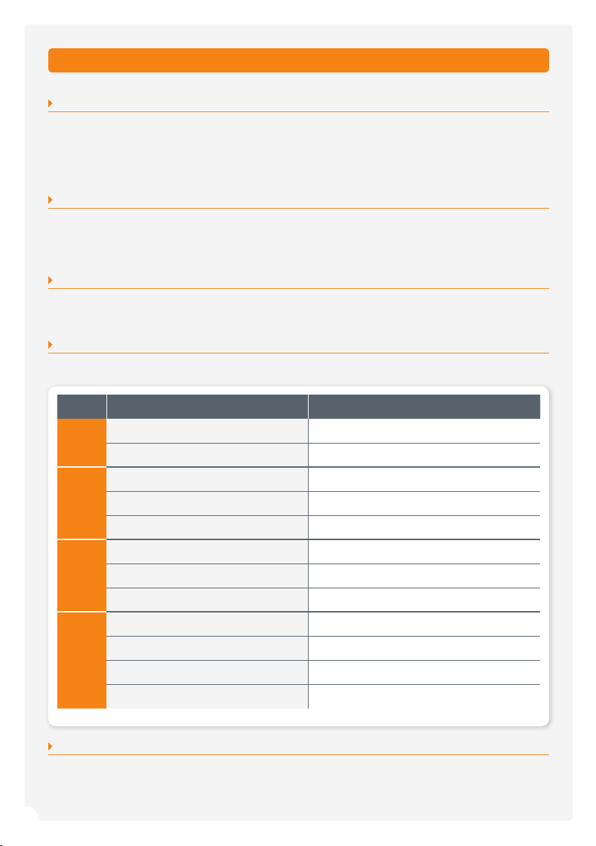
STEP 7 —LED OPERATION
The LEDs on the product provide information on the operational status of the GL45-3G Unit.
STEP 8 —COMMISSIONING
The Unit should now be ready to report back to your Control Room. Please note that it can take up to three (3)
minutes to register onto the cellular network and be authorised by the Servers.
*Normal operation
LED ACTIVITY INDICATION
HB
Green Flash* Signal strength OK / processor OK
Red Flash Signal strength low or trying to connect
MOBILE
Green On* Unit is online
Red Blinking Data trafc on 3G/GPRS
Not On No connection on 3G/GPRS network
IP
Green On* Unit is connected to IP network
Red Flash Data trafc on IP network
Not On No connection to IP network
CID
Green On* Alarm Panel has sent a valid Contact ID event
Red On (permanently) Alarm Panel dialler lead faulty
Red On (3 secs) followed by Green Blinking The line has been captured and data is being sent
Not On No valid Contact ID event has occurred
3
5 easy steps for activation and commissioning
SafeDial™ Toolbox
Installation and Connection Details (continued)
Fit the antenna and ensure all cabling is completed.
Before applying power to the unit, activation must be
completed via the SafeDial Toolbox App.
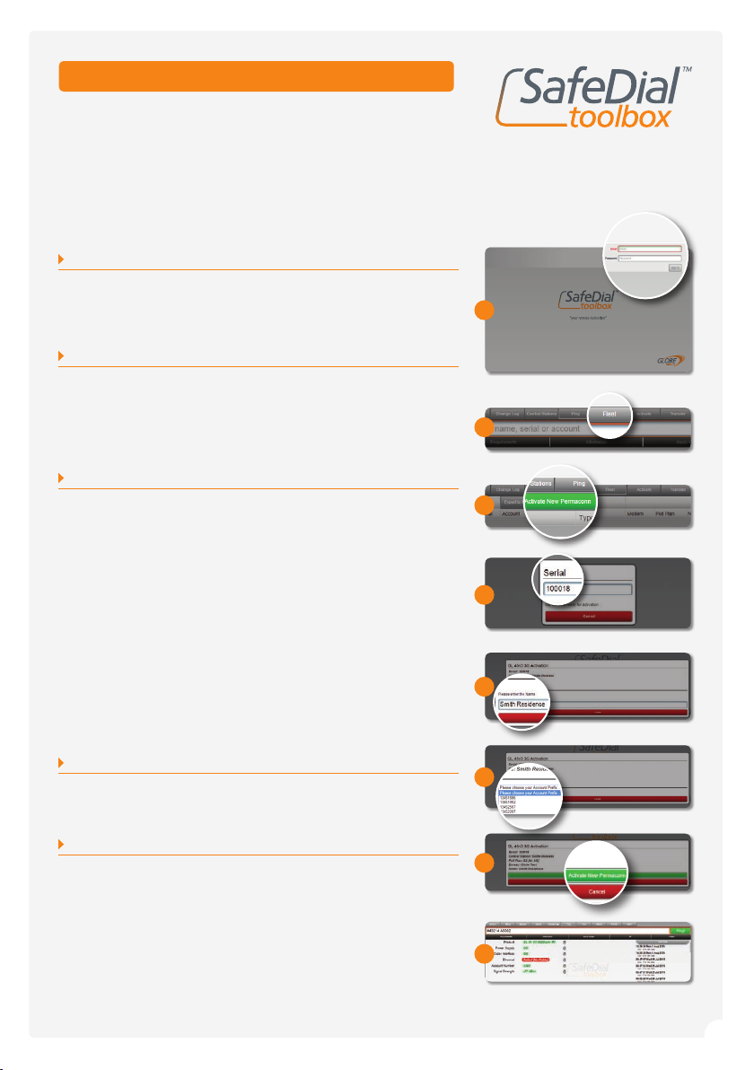
STEP 1 —LOG INTO SAFEDIAL TOOLBOX
Go to https://safedial.permaconn.com on your PC, tablet or
smartphone to arrive at the login portal. Login using the “Email”
and “Password” sent with your order conrmation. [Screen 1]
STEP 2 —TAB SELECTION
Once you sign in, you will be greeted with the Ping tab.
Select the Fleet tab. [Screen 2]
(NB: For smartphone users, this is selected from the menu
at the bottom right hand side of your screen).
STEP 3 —ACTIVATING A NEW SAFEDIAL UNIT
Once in the Fleet tab, click on “Activate new Permaconn”. [Screen 3]
A text box will open in the screen, please follow the prompts as
the screens progress.
a) Enter the serial number, which can be located on the product box or
on the back of the product. The next window will automatically load.
b) Enter the description you would like to have associated to the unit
(i.e. customer name, address etc.)
Press “Tab” for the next window to load.
c) Select your 1345 number from the dropdown box.
(NB: this screen will not appear if you only have one (1) 1345 number
registered with Globe Wireless).
d) Check this information is correct, and click
“Activate New Permaconn”.
STEP 4 —POWER UP AND CHECK LED INDICATORS
Successful power-up and operation is indicated by the LED patterns
being displayed. Refer to page 2 of this user guide.
STEP 5 —OPERATING AND TESTING
After activation, click on the Ping tab and enter the unit’s serial number
or your CMS Account number into the text box and select the unit from
the drop down list that will appear. This will automatically “Ping” the
unit. If the activation was successful, SafeDial Toolbox will respond with
the unit’s conguration details. [Screen 5]
For detailed instructions regarding each screen within the Ping tab,
please refer to the User Manual.
5
3
2
a
b
c
d
1