Supplied By www.heating spares.co Tel. 0161 620 6677
3221462C
Instructions for Use
General Notes and Information
Please read these instructions and follow them carefully for the
safe and economical use of your boiler.
Important Notice
This boiler is for use only on G20 gas.
The convection air openings on the boiler must NEVER be
obstructed.
The Gas Safety (Installation and Use)
Regulations
In your interests and that of gas safety it is the Law that ALL gas
appliances are installed by a competent person in accordance
with the current issue of the above regulations.
Maintenance
To ensure the continued efficient and safe operation of the boiler
it is recommended that it is checked and serviced at regular
intervals.Thefrequencyofservicingwilldependupontheparticular
installation and usage, but in general once a year should be
enough.
To obtain service, please call your installer, or Heatcall (Glow-
worm’s own service organisation) using the telephone number
given on the controls tray.
If the appliance is installed in a rented property there is a duty of
careimposedon the owner of thepropertyby the current issue of
the Gas Safety (Installation and Use) Regulations, Section 35.
It is the Law that servicing is carried out by a competent person.
Please be advised that the ‘Benchmark’ logbook should be
completed by the installation engineer on completion of
commissioning and servicing.
AllCORGIRegisteredInstallerscarryaCORGIIDcard,andhave
a registration number. Both should be recorded in your boiler
Logbook. You can check your installer is CORGI registered by
calling CORGI direct on :- 01256 372300.
Gas Leak or Fault
Ifagasleakorfaultexistsorissuspectedtheboilermustbeturned
offalsotheelectricalsupply. Advice/helpshouldbeobtainedfrom
your installation/servicing company or the local gas company.
Protection Against Freezing
If the boiler is to be out of use for any long period of time during
severe weather conditions we recommend that the whole of the
system, including the boiler be drained off to avoid the risk of
freezing up. If an immersion heater is fitted in the domestic hot
water cylinder make sure that it is switched off.
If you have a sealed water system you should contact your
installer/servicingcompanyasasealedwatersystemshouldonly
be drained, refilled and pressurised by a competent person.
Boiler Clearance
The boiler must be positioned so that at least the minimum
operational and servicing clearances are provided, see diagram
1.
If fixtures are positioned close to the boiler they should be made
removable for access to pipework.
Enough space must be left in front of the boiler for servicing.
Boiler in a Compartment
If the boiler is fitted in a compartment or cupboard, purpose built
ventilation must be provided and kept clear.
Do not use the enclosed space for storage.
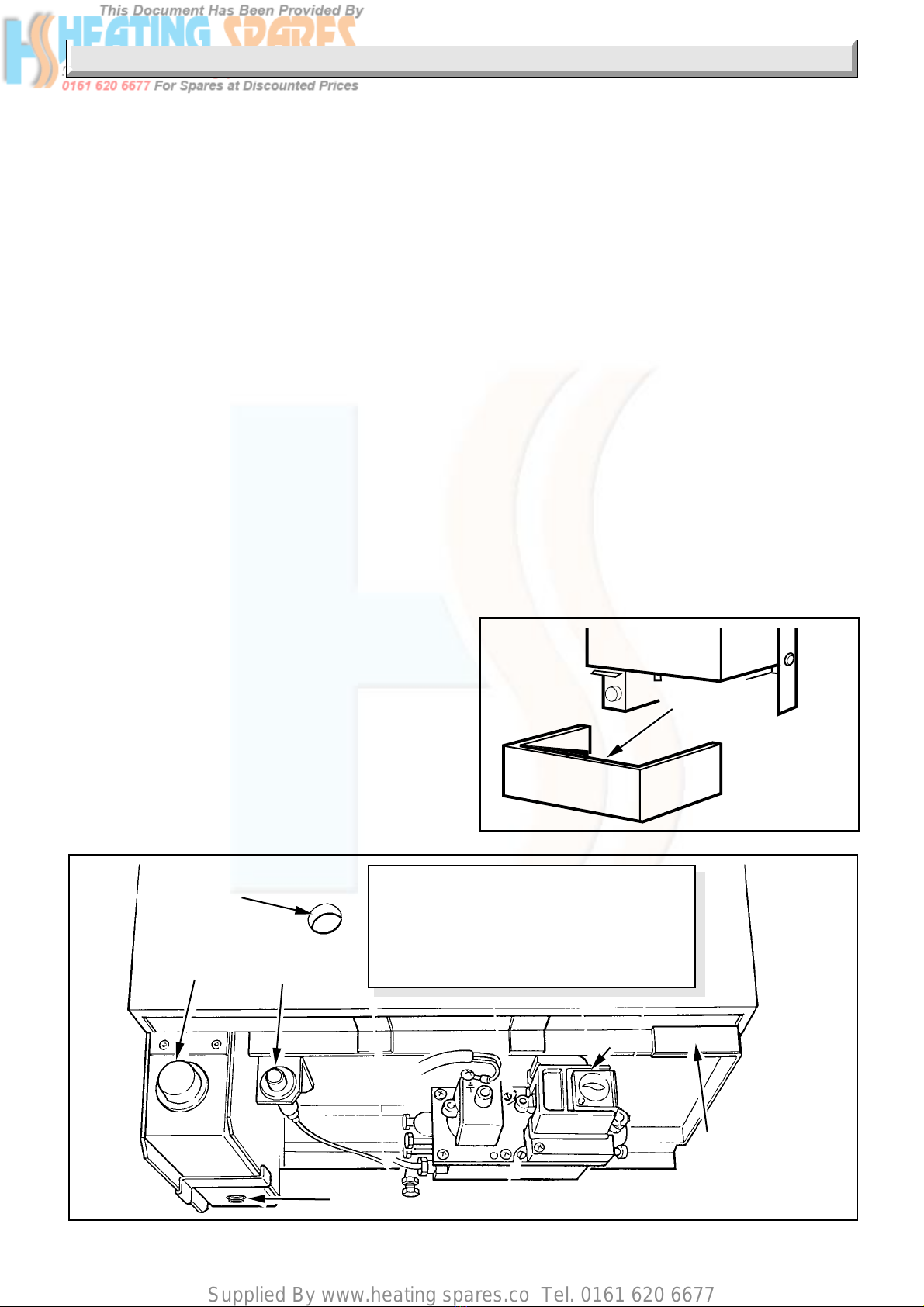
Boiler Identification
The type of boiler and its output can be checked against the
details inside the controls cover.
Overheat Cutoff Device
The boiler is fitted with a safety device to prevent damage
throughoverheating. Shouldthe boiler go out togetherwiththe
pilotfornoapparentreason,allowthesystemtocooldown,then
relight the boiler.
Should the problem persist, turn the boiler off and consult your
installation/servicing company.
Electrical Supply
WARNING. The boiler must be earthed.
The boiler must only be connected to a 240V~50Hz supply,
protected by a 3A fuse, maximum.
All wiring must be in accordance with the current issue of
BS7671.
Heat resistant cable having a conductor size of 0.75mm2, (24/
0.20mm) to BS6500 Table 16 must be used.
The colours of three core flexible cable are, Brown - live, Blue -
neutral, Green and yellow - earth.
As the marking on your plug may not correspond with these
colours continue as follows:
The wire coloured brown must be connected to the terminal
marked “L” or “Red”.
The wire coloured blue must be connected to the terminal
marked “N” or “Black”.
The wire coloured green and yellow must be connected to the
terminal marked “E”, Green or the earth symbol .
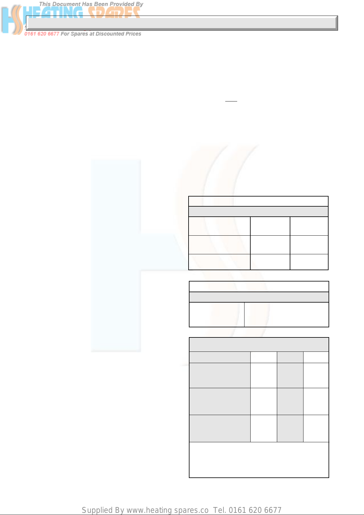
AL.H. and R.H. side of casing 25
BTop of casing 75
CBottom of casing 150
DFront of boiler (from a
permanent surface 305
OPEN FLUE BOILERS
Minimum Clearances from
Walss, Ceiling, Floor, etc.
Diagram 1
MINIMUM
CLEARANCES
A
B
2390
A
C