Glowworm Clearly Solar User manual

1
www.glow-worm.co.uk
Solar Thermal Flat Plate Collector
Installation Instructions
Clearly Solar
Horizontal On-roof mounting
15°- 75°
SRH 2.3

2
Guarantee Registration
Customer Service:
01773 596510
Technical Helpline:
01773 828300
General and Sales enquiries:
Tel. 01773 824639
Fax: 01773 820569
To register your Glow-worm appliance call:
0800 0732142
Benchmark places responsibilities on both manufacturers and installers. The purpose is to ensure that customers are provided
with the correct equipment for their needs, that it is installed, commissioned and serviced in accordance with the manufacturer’s
instructions by competent persons and that it meets the requirements of the appropriate Building Regulations. The Benchmark
Checklist can be used to demonstrate compliance with Building Regulations and should be provided to the customer for future
reference.
Installers are required to carry out installation, commissioning and servicing work in accordance with the Benchmark Code of
Practice which is available from the Heating and Hotwater Industry Council who manage and promote the Scheme.
Visit www.centralheating.co.uk for more information.
These Clearly Solar Flat Plate collectors come with a comprehensive manufacturer’s guarantee.
Details of the guarantee, and the terms and conditions that apply can be found on the Guarantee
registration card. We recommend you complete and return this as soon as possible.

3
These instructions must be handed to the user on completion of the installation.
CONTENTS DESCRIPTION SECTION PAGE
Warnings 4
Important Information 4
Statutory Requirements 5
Technical Specication 1 6
Technical Data 2 7
Solar Collector and Hydraulic
Connection Arrangement 3 8
Hydraulic Connection Kits 4 9
Roof Anchor - Type P 5 10
Roof Anchor - Type S 6 12
On-Roof Installation 7 13
GENERAL
INFORMATION
TECHNICAL
SPECIFICATION
ROOF MOUNTING

4
Important Information
General
These instructions must be handed to the user on completion
of the installation.
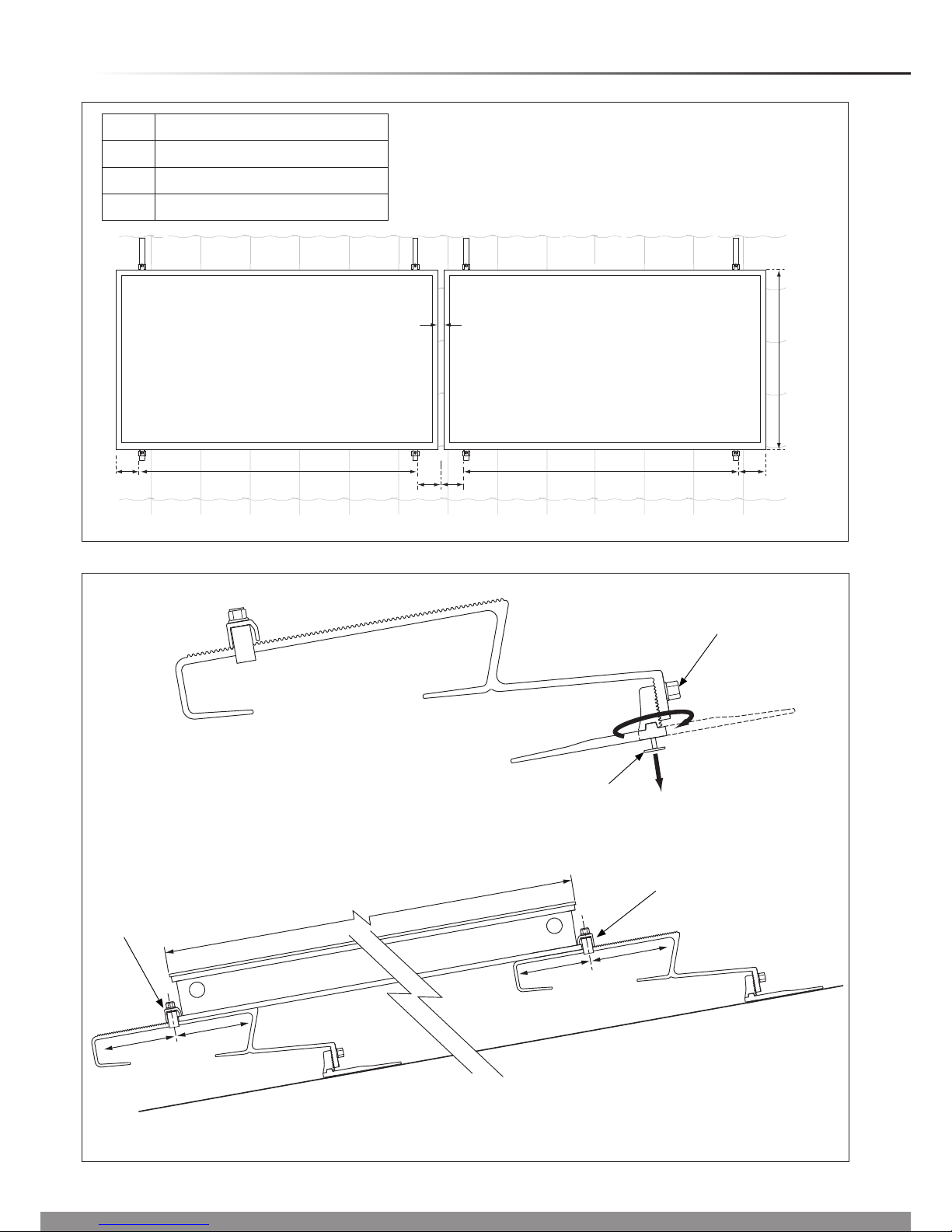
This installation instruction applies exclusively to the on-roof
mounting of the Clearly Solar, solar collector panel.
The solar collector panel is one component in a solar system
and it is recommended that you read all other component(s)
literature prior to installation.
We accept no liability for any damage caused by failure to
observe these instructions.
Manual Handling
With regards to the “Manual Handling Operations, 1992
Regulations”, this product exceeds the recommended weight
for a one man lift.
Recommend 2 person lift. Ensure safe lifting techniques are
used – keep back straight – bend using legs. Keep load as
close to body as possible. Ensure co-ordinated movements
during lift. Clear the route before attempting the lift. If
removing from truck straddle the load and tilt forwards to
facilitate secure grip. Do not twist – reposition feet instead.
Take care to avoid trip hazards, slippery or wet surfaces and
when climbing steps or ladders. Always use assistance if
required.
Installation of the solar collector panel will require a risk
assessment.
Testing and Certication
This solar collector panel is tested and certicated for safety
and performance. It is, therefore, important that no alteration
is made, without permission, in writing, by Glow-worm.
Any alteration not approved by Glow-worm, could invalidate
the certication, warranty and may also infringe the current
issue of the statutory requirements.
CE Mark
The CE mark on the solar collector panel indicates that
it complies with the basic requirements of the applicable
directives as stated on the data badge.
Damage from lightning
If the installation height is more than 20m or if the solar
panels are projected above the roof ridge, electro-conductive
components must be connected to a lightning protection
device.
Frost Protection
Under no circumstances should water be in the solar collector
panel if there is a danger of frost.
After pressurisation and ushing, the solar collectors panels
may contain water residues.
Immediately ll the solar system with solar uid. Check
the uid concentration with a frost protection tester. Water
remaining in the solar circuit may dilute the uid.
WARNINGS
Metal Parts
This solar panel contains metal parts (components) and care should be taken when handling,
with particular regard to edges.
Risk of death from falls and falling objects
Observe the national regulations for working at heights.
Danger of burning and scalding
In case of solar irradiation inside the units, solar panels can reach 200°C.
Remove the sun protection lm installed at the factory only after the solar energy system has been started up.
Sealed Components
Under no circumstances must the user interfere with or adjust sealed parts.

5
Statutory Requirements
IMPORTANT
Where no British Standards exists, materials and equipment
should be t for their purpose and of suitable quality and
workmanship.
The installation of this solar collector panel must be carried
out by a competent person in accordance the rules in force
in the countries of destination.
Manufacturer’s instructions must not be taken as overriding
statutory requirements.
Statutory Requirements
In GB, the installation of the solar collector panel must comply
with the requirements of the current issue of the following
regulations:
The manufacturer’s instructions supplied.
The appropriate Buildings Regulations either The Building
Regulations, The Building Regulations (Scotland),The
Building Regulations (Northern Ireland).
Working at Heights Regulations 2005.
Connecting thermal solar appliances.
Lightning protection requirements.
Equipotential bonding of electrical installations.
The Health and Safety at Work Act
Control of Substances Hazardous to Health (COSHH).
The Current I.E.E. Wiring Regulations.
The Water Supply (water ttings) Regulations 1999 or the
Water Byelaws 2000 (Scotland).
Where no specic instructions are given, reference should be
made to the relevant British Standard Code of Practice.
Regulations for the prevention of accidents
At all times follow the national regulations on working at
heights.
Make sure there is suitable safety equipment such as
scaffolding or protective walls to prevent falling from roofs.
Fall protection systems such as the Glow-worm fall protection
system (item no. 0020054985) also has a fall arresting device
if the roof scaffold and protective roof wall are inappropriate
for the specic task.
Only use tools and equipment such as lifting gear or ladders
in accordance with the lifting regulations.
Cordon off areas below the working area sufciently to protect
people from falling objects.
Mark the working area, for example with warning signs as
described by the national regulations.

6
Design Description
The Clearly Solar, solar at plate collector, collects the
available solar radiation and transfers the heat through the
solar uid to be utilised by the system.
It has been designed to compliment the complete range of
Glow-worm solar system components.
The kits are suitable for roof pitches between 15°- 75°, please
choose from the table below.
The solar thermal at plate collector includes a saltwater-
resistant aluminium frame as well as a copper surface
absorber with a high selective coating.
The at plate collector has a CFC-free, standstill temperature-
resistant mineral wool insulation for long-life and excellent
heat insulation.
Hydraulic connections are tool free with double ‘O’ ring
sealing. The sensor sleeve is integrated into the hydraulic ow
connection.
The following kits are available and dependant upon the
number of collectors, the quantities required are listed in the
following tables and illustrated in the appropriate sections:-
1 Technical Specication
On-roof installation components
1.1 On-roof mounting
With on-roof mounting, at collectors are fastened to
horizontal mounting rails quickly and reliably with attachment
clips. To ensure compatibility with different roongs, two
different roof anchors are available:
- Type P for high prole (pantile)
- Type S for at prole (slate) and extremely high protruding
tiles (e.g. Mediterranean clay tiles).
High profile tiled roof (pantile)
Number of collectors 12345678910
Type P anchor part no. 0020060302 - Section 5 12345678910
Easy fit hydraulic connection set
part no. 0020060207 1111111111
Easy fit hydraulic extension set
part no. 0020055175 -123456789
Collector panel 1 2 3 4 5 6 7 8 9 10
Low profile tiled roof (slate)
Number of collectors 12345678910
Type S anchor part no. 0020055184 - Section 6 12345678910
Easy fit hydraulic connection set
part no. 0020060207 1111111111
Easy fit hydraulic extension set
part no. 0020055175 -123456789
Collector panel 1 2 3 4 5 6 7 8 9 10

7
2 Technical Data
80
2033
1178
1233
1978
79
79 1075
14921
Diagram 2.1
Horizontal Collector
Appliance designation Unit. Clearly Solar
Absorber type Serpentine
Gross area m22.51
Aperture surface area m22.35
Absorber surface area m22.33
Absorber Aluminium (vacuum coated) 0.5 x 1178 x 1978
Dimensions (L x W x H) mm 1233 x 2033 x 80
Weight (Dry) kg 38
Fluid content l 2.16
Copper pipe connection, at-face Ø mm G 3/4" (DN16)
Insulation thickness mm 40
Max. operating pressure bar 10
Glass type Solar safety glass (prismatic structure)
Glass covering mm 3.2 (thickness) x 2033 x 1233
Coating High selective (blue) α = 95% ε = 5%
Solar safety glass transmission t(dew) %t = 91
Absorber emission ε(epsilon) % 5 ± 2
Back wall insulation mm, W/mk, kg/m 95 ± 2
Stagnation temperature °C 210
Efciency η0% 80
Heat capacity Ws/ (m•K) 5014
Efciency coefcient k1 W/(m2•K) 3.7
Efciency coefcient k2 W/(m2•K2) 0,012

8
3 Solar Collector and Hydraulic Connection Arrangement
Solar Collector
The recommended collector arrangements are shown below.
Hydraulic Connections
It is recommended that the hydraulic connections should be
made as shown below.
14 5
...
19 10
...
Diagram 3.2
15045
6 and up to 10 max Collectors
THE HYDRAULIC FLOW MUST BE DIAGONAL
1-5 Collectors
THE HYDRAULIC FLOW CAN BE DIAGONAL OR TOP AND BOTTOM

9
4 Hydraulic Connection Kits
Diagram 4.1
15188
2
1
3
5
5
4
7
56
7
Easy fit hydraulic connection set - Kit No. 0020060207
Part Description Qty.
1 Upper supply (with probe) 1
2 Return (inlet) 1
3 Lower plug 1
4 Upper plug (with ventilation) 1
5 Securing clip 4
Easy fit hydraulic extension set - Kit No. 0020055175
Part Description Qty.
6 Pipe coupling 2
7 Securing clip 4

10
5 Roof Anchor - Type P
Diagram 5.1
Distance in milimetres
A1233
B200 - 300
C1433 - 1633
Diagram 5.2
SECURING
SCREW
ROOF ANCHOR TYPE P
B
CCB
BB
A
74
15153
15186
BOTTOM PLATE
SECURING SCREW
*120 *120
1233
*120 *120
COLLECTOR CLAMP
COLLECTOR
CLAMP
15408
* Total adjustment of collector clamp can
be 240mm to suit site conditions and
reduce the need to cut tiles

11
IMPORTANT
● With due regard to the complete weight of the solar
collector system, (refer to technical data) ensure the roof
rafters and battens are in good condition and have
sufcient load carrying capacity and the battens are
secure.
5.1 Fixing roof anchor type P
Remove the roof tiles to expose the roof battens and rafters
where required, please refer to diagram 5.1 and 5.2 for
position of brackets.
If required loosen the securing screw, see diagram 5.2.
Using a 5mm Allen key, release the bottom plate securing
screw and swivel 180oand secure.
Position the roof anchor on the rafter, see diagram 5.3.
Ensure that the roof anchor is secured to the rafter with the
screws supplied.
Re-position the tiles ensuring that the roof is water tight before
tting the collector.
5 Roof Anchor - Type P
15405
Diagram 5.3

12
6 Roof Anchor - Type S
IMPORTANT
● With due regard to the complete weight of the solar
collector system, (refer to technical data) ensure the roof
rafters and battens are in good condition and have
sufcient load carrying capacity and the battens are
secure.
6.1 Roof anchor type S
Refer to diagram 6.1.
Remove the tiles where required, refer to diagram 5.1.
The roof anchor must be secured to a rafter.
Ensure that the roof anchor is secured with the screws
supplied.
Slide the tiles back to their original position.
15162
Diagram 6.1

13
7 On-Roof Installation
7.1 Collector installation
Ensure the mounting brackets are level before securing, see
diagram 7.1.
Position the collector, protective side uppermost, on the
mounting bracket and beneath the clamp, see diagram 7.2.
NOTE: The design is symmetrical and does not have a top or
bottom.
IMPORTANT: Do not remove the protective lm until the
system is to be commissioned
Move the clamp into position ensuring the correct
engagement of both clamps onto the collector.
Secure the clamps.
Diagram 7.1
15177
Diagram 7.2
15178
STRAIGHT EDGE
COLLECTOR CLAMP (UPPER)
MOUNTING
BRACKET
MOUNTING BRACKET

14
7 On-Roof Installation
Insert the pipe couplings up to the limit stop into the
corresponding openings on the side of the collectors, see
diagram 7.3.
Secure the pipe coupling with the securing clip
Place the next collector on the lower mounting bracket. Slide
the collector up to the rst collector paying attention to the
pipe couplings, see diagram 7.4.
When fully inserted to the limit stops, ensure that the pipe
couplings are secured with the securing clips.
Diagram 7.3
15168
Diagram 7.4
15180
SECURING
CLIP
PIPE COUPLING
PIPE COUPLING
SECURING
CLIP

15
7 On-Roof Installation
Diagram 7.5
15181
With regards to the hydraulic system you have chosen, insert
and secure the hydraulic connections, see diagrams 7.5 and
7.6.
Connect the collector Flow and Return to the system circuit.
Ensure that all of the following steps have been performed:-
- All the connections have been xed with securing clips.
- All hydraulic connections laid properly.
- The collector sensor has been connected.
- The collectors are connected to a lightning protection
device.
- A pressure test carried out and all connections are tight.
- All insulation is intact.
NOTE: After initial commissioning and according to the
season, high outside temperature oscillations can cause
condensation in the collector, this is normal.
Diagram 7.6
15182
COLLECTOR SENSOR
COLLECTOR SENSOR
1 - 5 Collectors
6 or more Collectors

16
Glow-worm, Nottingham Road, Belper, Derbyshire. DE56 1JT
Because of our constant endeavour for improvement, details
may vary slightly from those shown in these instructions.
0020080932-02 03.09
Table of contents