Installation requirements
#When preparing the installation site please take into consideration that this
equipment is for restricted access locations only!
•Never install the processor in explosive environments.
•It is the responsibility of the owner and operator/s of this processor, that the
installation is made in accordance with local regulations, and by engineers
authorized to carry out plumbing and electrical installations.
•Installation must be performed only by service technicians who are trained in
installing the equipment.
•The manufacturer cannot be held responsible for any damage caused by incorrect
installation of this processor.
Technical data
•Observe technical data from the processor name plate located on the rear panel of
the processor.
Notes, Cautions, and Warnings
Throughout the manual notes, cautions, and warnings are indicated with various icons
and written in bold like the example below:
$When lifting be careful not to damage any of the drain equipment at the right
side of the processor.
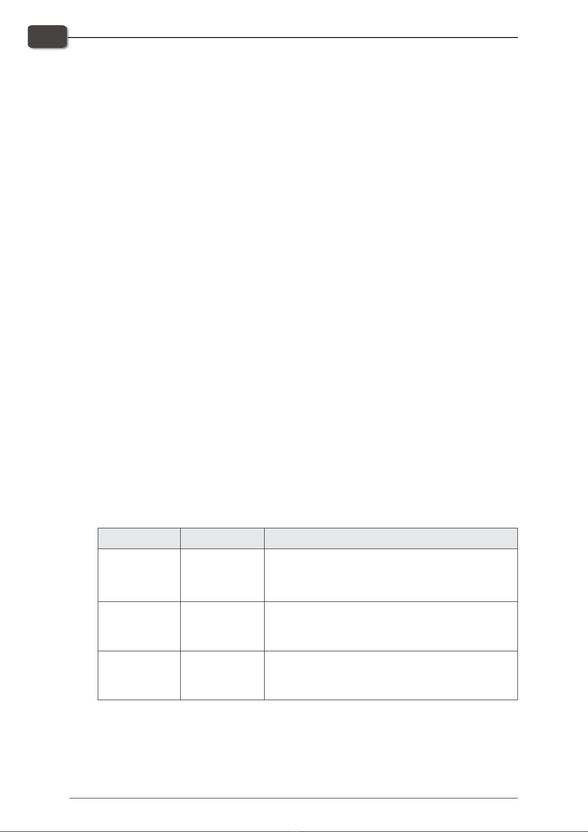
Explanations:
Symbol Meaning Explanation
"Note
The operator should observe and/or act according to the
information in order to obtain the best possible function of
the equipment.
$Caution
The operator must observe and/or act according to the
information in order to avoid any mechanical or electrical
damage to the equipment.
#Warning
The operator must observe and/or act according to the
information in order to avoid any personal injury.
Important
Always refer to this manual. If the warnings, cautions and notes given here are ig-
nored, then the warranty may be invalidated.
Installation Manual - Plate Processor 150 1049
1-2 Introduction
Installation requirements