Binks 183S-211-CE User manual

183 RANGE PRESSURE FEED TANKS with and without
AGITATION, 9.5, 40 and 60 Litre capacities
Important: Read and follow all instrucons and SAFETY
PRECAUTIONS before using this equipment. Retain for future
reference.
DESCRIPTION
These Pressure Tanks are CE marked in accordance with the
Pressure Equipment Direcve 97/23/EC and ATEX Direcve
94/9/EC Cat 2 G X for use in Zones 1 and 2. The agitators used
in the agitated models are ATEX cered to Cat 1/2 Gc T4.
They are suitable for use with ammable materials. 183S
models are suitable for use with water based and more
corrosive materials.
These pressure tanks are designed as a pressure container to
supply liquid material at a constant preset pressure up to a
maximum of 7.6 bar (110 psi). The tanks are built to ASME BPV
XIII standards. 183G models are constructed from Galvanised
carbon steel. 183S models are constructed from stainless steel. A
polyethylene liner is included for easy clean up.
Tank Model Capacity Material Type Agitaon
183S-210-CE 9.5 litre Stainless Steel None
183S-211-CE 9.5 litre Stainless Steel Direct Drive
183S-212-CE 9.5 Litre Stainless Steel Manual
183S-213-CE 9.5 Litre Stainless Steel Gear-reduced (Heavy-duty)
183S-1010-CE 40 litre Stainless Steel None
183S-1012-CE 40 litre Stainless Steel Manual
183S-1013-CE 40 litre Stainless Steel Gear-reduced (Heavy-duty)
183G-1010-CE 40 litre Galvanised Steel None
183G-1012-CE 40 litre Galvanised Steel Manual
183G-1013-CE 40 litre Galvanised Steel Gear-reduced (Heavy-duty)
183S-1510-CE 60 litre Stainless Steel None
183S-1512-CE 60 litre Stainless Steel Manual
183S-1513-CE 60 litre Stainless Steel Gear-reduced (Heavy-duty)
Part Sheet
77-2931/2
EN

2© ITW FINISHING SYSTEMS AND PRODUCTS
READ THE MANUAL
Before operating finishing equipment, read and understand all
safety, operation and maintenance information provided in the
operation manual.
GET IMMEDIATE MEDICAL ATTENTION
To prevent contact with the fluid, please note the following:
a) Never point the gun/valve at anyone or any part of the body.
b) Never put hand or fingers over the spray tip.
c) Never attempt to stop or deflect fluid leaks with your hand, body
glove or rag.
d) Always have the tip guard on the spray gun before spraying.
e) Always ensure that the gun trigger safety operates before spraying.
f) Always lock the gun trigger safety when you stop spraying
READ THE MANUAL
All personnel must be trained before operating finishing
equipment.
EQUIPMENT MISUSE HAZARD
Equipment misuse can cause the equipment to rupture,
malfunction, or start unexpectedly and result in serious injury.
MEDICAL ALERT
Any injury caused by high pressure liquid can be serious. If you are
injured or even suspect an injury;
a) Go to an emergency room immediately.
b) Tell the doctor you suspect an injection injury.
c) Show the doctor this medical information or the medical alert card
provided with your airless spray equipment.
d) Tell the doctor what kind of fluid you were spraying or dispensing.
e) Refer to the Material Safety Data Sheet for specific information.
DE-ENERGIZE, DEPRESSURIZE, DISCONNECT AND
LOCK OUT ALL POWER SOURCES DURING
MAINTENANCE
Failure to De-energize, disconnect and lock out all power
supplies before performing equipment maintenance could
cause serious injury or death.
HIGH PRESSURE CONSIDERATION
High pressure can cause serious injury. Relieve all pressure
before servicing. Spray from the spray gun, hose leaks, or
ruptured components can inject fluid into your body and cause
extremely serious injury.
WEAR RESPIRATOR
Toxic fumes can cause serious injury or death if inhaled. Wear a
respirator as recommended by the fluid and solvent manufacturer’s
Material Safety Data Sheet.
PRESSURE RELIEF PROCEDURE
Always follow the pressure relief procedure in the equipment
instruction manual.
TOXIC FLUID & FUMES
Hazardous fluid or toxic fumes can cause serious injury or death if
splashed in the eyes or on the skin, inhaled, injected or swallowed.
LEARN and KNOW the specific hazards or the fluids you are using.
KEEP EQUIPMENT GUARDS IN PLACE
Do not operate the equipment if the safety devices have been
removed.
FIRE AND EXPLOSION HAZARD
Improper equipment grounding, poor ventilation, open flame or sparks
can cause hazardous conditions and result in fire or explosion and
serious injury.
AUTOMATIC EQUIPMENT
Automatic equipment may start suddenly without warning.
PROJECTILE HAZARD
You may be injured by venting liquids or gases that are released under
pressure, or flying debris.
INSPECT THE EQUIPMENT DAILY
Inspect the equipment for worn or broken parts on a daily
basis. Do not operate the equipment if you are uncertain about
its condition.
ELECTRIC SHOCK / GROUNDING
Improper grounding or sparks can cause a hazardous condition and
result in fire, explosion or electric shock and other serious injury.
NEVER MODIFY THE EQUIPMENT
Do not modify the equipment unless the manufacturer
provides written approval.
PINCH POINT HAZARD
Moving parts can crush and cut. Pinch points are basically any areas
where there are moving parts.
KNOW WHERE AND HOW TO SHUT OFF THE EQUIPMENT
IN CASE OF AN EMERGENCY
NOISE HAZARD
You may be injured by loud noise. Hearing protection may be required
when using this equipment.
STATIC CHARGE
Fluid may develop a static charge that must be dissipated
through proper grounding of the equipment, objects to be
sprayed and all other electrically conductive objects in the
dispensing area. Improper grounding or sparks can cause a
hazardous condition and result in fire, explosion or electric
shock and other serious injury.
PROP 65 WARNING
WARNING: This product contains chemicals known to the State of
California to cause cancer and birth defects or other reproductive harm.
WEAR SAFETY GLASSES
Failure to wear safety glasses with side shields could result in
serious eye injury or blindness.
IT IS THE RESPONSIBILITY OF THE EMPLOYER TO PROVIDE THIS INFORMATION TO THE OPERATOR OF
THE EQUIPMENT.
FOR FURTHER SAFETY INFORMATION REGARDING BINKS AND DEVILBISS EQUIPMENT, SEE THE
GENERAL EQUIPMENT SAFETY BOOKLET (77-5300).
WARNING CAUTION NOTE
Hazards or unsafe practices which
could result in severe personal
injury, death or substantial property
damage.
Hazards or unsafe practices which
could result in minor personal injury,
product or property damage.
Important installation, operation or
maintenance information.
Read the following warnings before using this equipment
In this part sheet, the words WARNING, CAUTION and NOTE are used to emphasize important safety information as follows:

3© ITW FINISHING SYSTEMS AND PRODUCTS
The following hazards may occur during the normal use of this equipment. Please
read the following chart before using the equipment.
HAZARD CAUSE SAFEGUARDS
Fire
Solvents and coangs can be highly ammable
or combusble, especially when sprayed.
Adequate exhaust must be provided to keep the air free
of accumulaons of ammable vapours.
Smoking must never be allowed in the spray area.
Fire exnguishing equipment must be present in the spray
area.
Fire-
Pressure tank
Vapours from ammable liquids can catch re or
explode.
Keep tank at least 10 feet away from sources of ignion.
Ignion sources include hot objects, mechanical sparks,
and arcing (non -explosion proof) electrical equipment.
Explosion Hazard –
Pressure Tank –
Stac Electricity
Stac electricity is created by the ow of uid
through the pressure tank and hose. If all parts
are not properly grounded, sparking may occur.
Sparks can ignite vapours from solvents and the
uid being sprayed.
Ground the pressure tank by connecng one end of 12
gauge (minimum) ground wire to the pressure tank and
the other end to a true earth ground. Local codes may
have addional grounding requirements.
See illustraon g 3 on page 7 for grounding and
grounding hardware required.
Explosion Hazard –
Pressure Tank –
Rupture
Making changes to a pressure tank will weaken
it.
Never drill into, weld, or modify the tank in any way.
Do not adjust, remove, or tamper with the safety valve. If
replacement is necessary, use the same type and rang of
valve.
Explosion Hazard –
Galvanized Tanks –
Material Compability
Halogenated hydrocarbon solvents – for
example 1-1-1 Trichloroethane and methylene
chloride – can chemically react with aluminium
parts and components and cause an explosion
hazard. These solvents will also corrode the
galvanized tank coang.
Read the label or data sheet for the material. Do not use
materials containing these solvents with galvanized
pressure tanks. Stainless steel tank models may be used
with halogenated solvents.
Refer to specicaons chart to ensure that uids are
chemically compable with the tank weed parts. Before
placing uids or solvents in tank, always read
accompanying manufacturer’s literature.
General Safety Improper operaon or maintenance may create
a hazard.
Operators should be given adequate training in the safe
use and maintenance of this equipment. Refer to Pressure
Systems Safety Regulaons 2000 Approved Code of
Pracce (UK) or relevant naonal regulaons in the
country of use.
WARNING PRESSURE RELIEF PROCEDURE
To reduce the risk of injury, follow the pressure relief procedure below
Before checking or servicing any part of the spray system
Before aempng removal of ll port cap or tank cover
Whenever the tank is le unaended
1. Turn o the main air supply to the tank.
2. Close the air inlet valve located on the tank air manifold.
3. Bleed o air in the tank by turning the air relief valve (5) thumb screw counter clockwise. Wait unl all the air has
escaped through the valve before removing the pressure tank cover or ll port cap.
4. Leave the air relief valve open unl you have reinstalled the tank cover or ll port cap.
High pressure can cause
serious injury.
Pressure is maintained in
a pressure tank aer the
system has been shut
down.
Always follow this
procedure to relieve
pressure from the tank.

4© ITW FINISHING SYSTEMS AND PRODUCTS
SPECIFICATIONS
183G GALVANIZED TANKS 183S STAINLESS STEEL TANKS
Maximum Working Pressure 110 psi
Tank Shell SA-414 Steel, Galvanized (Zinc) 304 Stainless Steel
Tank Lid SA-414 Steel, Galvanized (Zinc) 304 Stainless Steel
Fluid Tube 3/8 in. Steel Pipe, Galvanized 3/8 in. SS Pipe, 316 Stainless Steel
Fluid Outlet (Elbow) Steel, Zinc Plate 316 Stainless Steel
Fluid Valve, Outlet Brass, Nickel Plate
3/8-18 NPS(M)
316 Stainless Steel
3/8-18 NPS(M)
Agitator Paddle/Propeller Conducve Nylon, Glass Filled
Agitator Sha 303 Stainless Steel
Agitator Sha Seal Engineered PTFE, Stainless Steel
Air Manifold Steel, Zinc Plate
Plug (Air Manifold Coupling) Steel, Zinc Plate 18-8 Stainless Steel
Boom Outlet (Oponal Kit) 304 Stainless Steel 3/4-14 NPS(M)
AGITATION OPTIONS
Type Applicaon
No Agitaon Materials that require minimal or no mixing and/or readily hold any solids
in suspension.
Direct Drive Agitaon Low to medium viscosity materials that require mixing and/or solids
suspension.
Gear-reduced Drive Agitaon Heavy-duty agitator for medium to high viscosity materials that require
mixing and/or solids suspension.

5© ITW FINISHING SYSTEMS AND PRODUCTS
INSTALLATION
Regulator Assembly
1. Unbox the regulator assembly and mount
it on the manifold connecon with the
swivel connecon .
2. If BSP thread is required, aach adaptors
to the ball valve uid outlet ball valve and
the air inlet/outlet connecons on the
regulator.
3. For agitator models, connect the air hose
from the adjusng valve on the drive
motor to the swivel elbow on the
regulator.
Air Supply
1. The air supply line should pass through an
air lter/regulator to lter dirt from air
and remove entrained water and oil.
Connect the air supply hose to the air inlet
ng on tank regulator. Connect the
atomisaon air hose to the air outlet
ng which is directly opposite air inlet
ng.
2. Connect material hose to the uid outlet
ball valve.
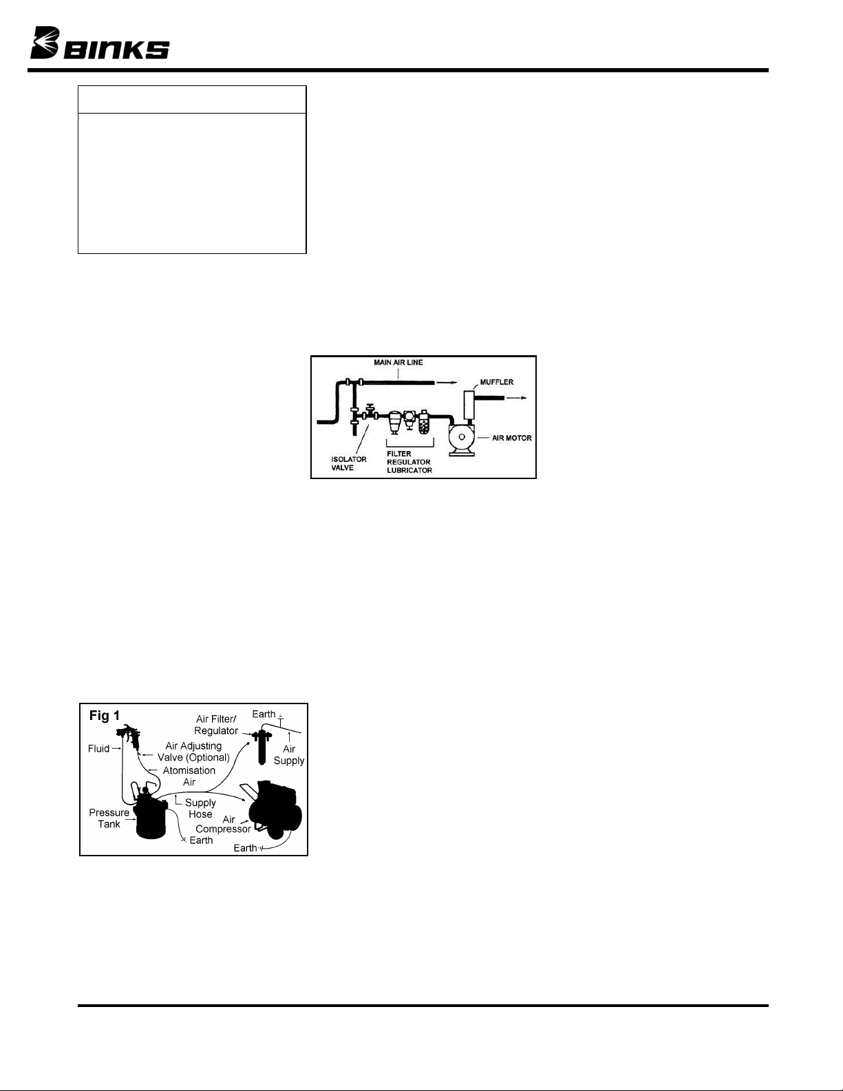
3. See Figure 1 below for a typical
installaon.
4. To avoid hazards from electrostac
discharges, the tank should be earthed
directly via an earth clamp. There is an
earth connecon point on the lower part
of the tank shell. See p7 for connecon
diagram. Air supply hoses should be
conducve to avoid creang electro stac
charges. Check connuity to earth before
using the equipment.
LUBRICATION – Agitated
Models
1. An automac air line lter/lubricator
should be installed in the air supply line no
more than 0.5m from the air motor. The
lter should be 5 micron. Install the
lubricator level with or above the motor
so the oil mist will blow directly into or
down into the motor (see Fig. 2).
2. Fill the oil reservoir with SAE 10W motor
oil. Adjust lubricator to feed 1 drop of oil
for every 1400 litres (50 cfm) of air or 1
drop per minute for connuous running.
PREPARATION
Mix and prepare material to be used
according to manufacturer’s instrucons.
Strain material through a ne mesh screen to
remove lumps, skin, and foreign maer that
might enter and clog uid passages and/or
spray equipment.
Follow pressure relief procedure on page 3..
To add material to the tank, remove the lid
and pour directly into the tank or container.
Replace the lid assembly and ghten thumb
screws securely.
Connect the material hose to the uid outlet
ball valve.
OPERATION
1. Close the air inlet valve to tank. Turn
handle on regulator counter clockwise
unl spring tension is relieved.
2. Turn on air supply to the tank.
3. Open the air inlet valve to the tank.
4. Open the uid outlet valve.
5. Turn handle on tank pressure regulator
clockwise to pressurize tank.
6. Turn on atomizaon air to spray gun at
source of supply.
7. Test spray. For further instrucons
consult literature provided with spray gun.
8. If an air motor driven agitator is used,
start the agitator by slowly opening up the
needle valve. Air motor speed should be
regulated according to the nature of the
material being agitated.
MAINTENANCE
To clean equipment, proceed as follows:
1. Turn o the air supply.
2. Follow the pressure relief procedure.
3. Turn T-handle adjusng screw on tank
uid pressure regulator counter clockwise
unl no spring pressure is felt.
4. Loosen thumb screws (17), p clamps (16)
back and p lid (11) to one side of tank.
Do not remove lid from tank.
5. To drain down the uid supply hose to the
gun, remove the Aircap and replace with
about 2 turns. Trigger the spaygun into
the booth , which will create a back
pressure in the uid line and force the
uid back into the tank.
6. Now remove the lid, empty and clean the
parts that have come into contact with the
material with compable cleaning
material.
7. When clean, pour a lile cleaning material
into the tank and replace the lid.
8. Repeat 1 to 5 of the OPERATION.
9. Do not turn on the atomising air to the
Gun. Make sure the Aircap is fully ght.
Trigger the gun and jet the cleaning
material into a container unl clean
material is visible.
10. Remove solvent and replenish with new
material as from INSTALLTION secon 1
onwards.
LUBRICATION – Agitated
Models
Refer to the service manual SBBI-E-19-095
provided with the air motor for lubricaon
informaon.
The bearings in the agitator bearing assembly
are impregnated with special non-gumming
oil. Addional lubricaon is not required.
The agitator sha seal does not require
lubricaon.
PREVENTATIVE MAINTENANCE
1. Keep the safety valve clean at all mes.
Check regularly by pulling the ring to
ensure the valve is free to operate.
WARNING
High pressure can cause serious injury.
Pressure is maintained in a pressure
tank aer the system has been shut
down.
Follow the pressure-relief procedure on
page 3 before opening the lid or ll port
or performing maintenance on the tank.
Fig 2

6© ITW FINISHING SYSTEMS AND PRODUCTS
SERVICE CHECKS
FAULT CONDITION CAUSE CORRECTION
Air escaping from port on regulator cap. Broken or damaged diaphragm Replace diaphragm.
Pressure creepage registered on gauge. Dirty or worn valve seat in regulator. Clean or replace valve seat.
Material tends to sele out rapidly. Not enough agitaon of material. Increase agitaon.
Air leakage at agitator seal. Defecve seal assembly. Replace.
Paint geng into bearing assembly of
agitator.
Paint level in tank too high.
Defecve agitator sha seal.
Keep uid level under bearing ass’y.
Replace.
Fluid or air leak at lid gasket. Thumb screw not ght.
Defecve lid gasket.
Tighten.
Replace.
Fluid or air leak at ll port gasket. Fill port cap not ght.
Defecve ll port gasket.
Tighten uid tube into lid.
Reduce speed of agitator.
Air mixing with paint Fluid tube not sealed to lid.
Excessive agitaon.
Tighten uid tube into lid.
Reduce speed of agitator.
FOR FURTHER SAFETY INFORMATION REGARDING BINKS AND DEVILBISS EQUIPMENT, SEE THE
GENERAL EQUIPMENT SAFETY BOOKLET (77-5300).

7© ITW FINISHING SYSTEMS AND PRODUCTS
PG
For boom outlet
conversion remove and
discard plug.
PG
PETROLEUM
JELLY/GREASE
Note
Use PTFE based thread sealant on all
air and uid connecons
183S RANGE - 9.5 LITRE TANK ASSEMBLIES
For regulator parts see page 13

8© ITW FINISHING SYSTEMS AND PRODUCTS
Note
Open side of sha seal (31) faces
downwards.
Retainer (32) required only for vacuum
operaon.
DIRECT DRIVE AGITATOR-REGULATOR HOOK-UP
DIRECT DRIVE AGITATOR
PG
PETROLEUM
JELLY/GREASE
PG
PG
Refer to SBBI-E-19-095 for
informaon about the
Agitator drive unit. Complete
drive ref is QMS-430-CE
FIG 3
For regulator parts
see page 13

9© ITW FINISHING SYSTEMS AND PRODUCTS
GEAR-REDUCED AGITATOR
Note
Use PTFE based thread sealant on all
air and uid connecons
Refer to SBBI-E-19-095 for informaon about
maintenance of the agitator assembly. Agitator
ref is QMS-431-CE, Drive motor QS-5012-CE
PG
PETROLEUM
JELLY/GREASE
PG
PG
GEAR-REDUCED DRIVE AGITATOR-REGULATOR
HOOK-UP
Note
Open side of sha seal (46) faces
downward.
Retainer (47) required only for
vacuum operaon.
For regulator parts see page 13

10 © ITW FINISHING SYSTEMS AND PRODUCTS
PARTS LIST—183S RANGE 9.5 LITRE STAINLESS STEEL TANK ASSEMBLIES
83S-210-CE 83S-211-CE 83S-213-CE
ITEM PART NO. DESCRIPTION QTY QTY QTY
1QN-97 HANDLE 1----- -----
2QMS-2PLUG (NON-AGITATED MODELS ONLY) 1----- -----
3SSG-8184-K2 O-RING (KIT OF 2) 111
4QMG-21 AIR MANIFOLD 111
5SS-2707 AIR RELIEF VALVE 1/4 NPT-M111
6TIA-4110-CE SAFETY VALVE ASSY, 110 PSI 111
7•SSP-1939 (S.S.) STR ELBOW (3/8-18) 111
8VA-527 BALL VALVE 3/8 NPS OUTLET 111
983-524-KFILL PORT CAP (INCL ITEM 10) 111
10 83-1207-K5 FILL PORT CAP GASKET (QTY PACK) 111
11 QMS-416-1TANK LID 111
12 20-6858 PLUG (1/2-14) 111
13 QMS-80-1TANK GASKET 2 GAL 111
14 QMS-9-1FLUID TUBE (DIR DRIVE AGIT) 11-----
15 QMS-53-1FLUID TUBE (GEAR REDUCED AGIT) ----- ----- 1
16 QMG-43-CE CLAMP (SEE ITEM 20) 444
17 QMG-46-CE THUMBSCREW (SEE ITEM 20) 444
18 QMG-40-CE CLEVIS PIN (SEE ITEM 20) 444
19 SSN-2404-ZN COTTER PIN, 1/8 DIA. X 1" LG. (SEE ITEM 20) 444
21 PT-78-K10, K60 DISPOSABLE TANK LINER (10 OR 60 EACH) 111
22 QMS-502-1TANK & LUG ASSY 111
23 ----- BOTTOM PLUG 111
24 QMS-428 AIR MOTOR ASSY ----- 1-----
25 HAV-500-BAIR ADJUSTING VALVE ----- 1-----
26 H-2008 NIPPLE 1/4 NPS x 1/4 NPT ----- 1-----
27 •----- STREET ELBOW (1/4-18 NPT, BRASS) ----- 1-----
28 ----- SET SCREW (1/4-20 X 1/4) ----- 2-----
29 #----- ADAPTER (SEE ITEM 30) ----- 1-----
30 KK-4991 SEAL RETAINER KIT (INCL 28, 29, 34,35) ----- 1-----
31 ----- SHAFT SEAL 1/2 I.D. (DIR. DRIVE AGIT) ----- 1-----
32 ----- INTERNAL RETAINING RING (DIR. DRIVE AGIT) ----- 1-----
33 KK-5041 SHAFT SEAL KIT (DIR. DRIVE AGIT) ----- 1-----
34 •----- SET SCREW (1/4-20 X 1/4) S.S. ----- 2-----
35 #----- SHAFT COUPLING (SEE ITEM 30) ----- 1-----
36 QMS-73 AGITATOR SHAFT ----- 1-----
37 •----- SQ HD SET SCREW, 1/4-20 X 3/8, S.S. ----- 1-----
38 ----- PROPELLOR ----- 1-----
39 QMS-448-CE AGITATOR PROPELLER KIT (DIR. DRIVE) ----- 1-----
40 QMS-46 RETAINING NUT ----- ----- 1
41 KK-5049 THRUST WASHER (KIT OF 2/EA) ----- ----- 1
42 ----- THRUST COLLAR ----- ----- 1
43 •----- SET SCREW, 5/16-18 X 3/8 ----- ----- 1
44 QMS-447 THRUST COLLAR KIT (INCL. 42 and 43) ----- ----- 1
45 QMS-407 BEARING ASSY. ----- ----- 1
46 ----- SHAFT SEAL 5/8 I.D. (GEAR REDUCED AGIT) ----- ----- 1
47 ----- INTERNAL RETAINING RING (GEAR REDUCED AGIT) ----- ----- 1
48 KK-5042 SHAFT SEAL KIT (GEAR REDUCED AGIT) ----- ----- 1
49 QMS-5AGITATOR SHAFT ----- ----- 1
50 ----- AGITATOR PADDLE ----- ----- 1
51 ----- SOC HD CAP SCREW, 5/16-18 X 1-1/4, S.S. ----- ----- 1
52 QMS-449-CE AGITATOR PADDLE KIT (INCL 51 AND 52) ----- ----- 1
53 QS-5012-CE AIR MOTOR/GEARBOX DRIVE ----- ----- 1
54 HA-57011 AIR HOSE ASSY ----- ----- 1
55 SSP-30-ZN SWIVEL ELBOW ----- ----- 1
56 85-470 AIR CONTROL (NON-AGITATOR TANKS) 1----- -----
57 85-471 AIR CONTROL (AGITATOR TANKS) ----- 11
58 ¶CT-453 ADAPTOR 1/4” BSP (M) - 1/4” NPS (F) 222
59 ¶CT-454 ADAPTOR 3/8” BSP (M) - 3/8” NPS (F) 111
¶ BSP MODELS ONLY • Purchase locally

11 © ITW FINISHING SYSTEMS AND PRODUCTS
183S & G, 40 AND 60 LITRE TANK ASSEMBLIES
Note
Open side of sha seal (8)
faces downward.
Retainer (9) required only for
vacuum operaon.
PG
PETROLEUM
JELLY/GREASE
The Staonary Paddle Kit
(28) comes standard
only on 10 and 15 gallon
tanks.
The 5 and 10 gallon
tanks come standard
with one Agitator
Paddle Kit (26).
The 15 gallon
tanks come
standard with two
Agitator Paddle
Kits (26).
For boom outlet
conversion, remove and
discard plug
Note
Use PTFE based thread sealant on all air
and uid connecons
PG
PG
Agitator-Regulator Hook-Up
with Standard Regulaon.
Refer to SBBI-E-19-095 for informaon about
the Agitator drive unit, ref QS-5012-CE.
Complete drive ref is QMS-433-CE (40L) and
QMS-434-CE (60L)
For regulator parts see page 13

12 © ITW FINISHING SYSTEMS AND PRODUCTS
PARTS LIST - 183S - 40 AND 60 LITRE STAINLESS STEEL TANK ASSEMBLIES
183S-1010 183S-1013 183S-1510 183S-1513
ITEM PART NO. DESCRIPTION QTY QTY QTY QTY
1QMS-46 RETAINING NUT ----- 1----- 1
2QMG-85 THRUST WASHER ----- 2----- 2
3----- THRUST COLLAR ----- 1----- 1
4•----- SET SCREW (5/16-18 X 3/8) ----- 1----- 1
5QMS-447 THRUST COLLAR KIT (INCL 4 & 5) ----- 1----- 1
6QMS-407 BEARING ASSY-PLAIN STEEL ----- 1----- 1
7SSG-8184-K2 O-RING (KIT OF 2) 1111
8----- SHAFT SEAL 5/8 I.D. ----- 1----- 1
9----- INTERNAL RETAINING RING ----- 1----- 1
10 KK-5042 SHAFT SEAL KIT (INCL 8 & 9) ----- 1----- 1
11 QMS-3PLUG (NON-AGITATED MODELS ONLY) 1----- 1-----
12 TIA-4110-CE SAFETY VALVE ASSY, 110 PSI 1111
13 QMG-21 AIR MANIFOLD 1111
14 SS-2707 AIR RELIEF VALVE 1/4 NPT(M) 1111
15 83-524-KFILL PORT CAP (INCL ITEM 16) 1111
16 83-1207-K5 FILL PORT CAP GASKET 1111
17 SSP-1939 STREET ELBOW, 3/8-18 NPT, S.S. 1111
18 VA-527 BALL VALVE, 3/8 NPS OUTLET, S.S. 1111
19 QMS-417-1TANK LID 1111
20 QM-1458-1TANK GASKET 1111
21 •----- PLUG, 1/2-14 NPT, S.S. 1111
22 QMS-11-1FLUID TUBE 11----- -----
22 QMS-12-1FLUID TUBE ----- ----- 11
23 QMS-7AGITATOR SHAFT ----- 1----- -----
23 QMS-8AGITATOR SHAFT ----- ----- ----- 1
24 ----- AGITATOR PADDLE ----- 12
25 •----- SOC HEAD CAP SCREW, 5/16-18 X 1-1/4, S.S. ----- 2----- 3
26 QMS-444-CE AGITATOR PADDLE KIT (INCL 24 & 25) ----- 1----- 2
27 ----- STATIONARY PADDLE ----- 1----- 1
28 QMS-445-CE STATIONARY PADDLE KIT (INCL 25 & 27) ----- 1----- 1
29 PTL-412-K8 DISPOSABLE TANK LINER, 10-GAL ----- 1----- -----
29 PTL-415-K10 DISPOSABLE TANK LINER, 15-GAL ----- ----- ----- 1
30 QM-1352-CE THUMB SCREW (SEE ITEM 34) 6666
31 •SSN-2404-ZN COTTER PIN, 1/8 DIA. X 1" LG. (SEE ITEM 34) 6666
32 QMG-38-CE CLEVIS PIN (SEE ITEM 34) 6666
33 QMG-9-CE CLAMP (SEE ITEM 34) 6666
35 QMS-510-1TANK & LUG ASSY, 10-GAL ----- 1----- -----
35 QMS-515-1TANK & LUG ASSY, 15-GAL ----- ----- ----- 1
36 ----- BOTTOM PLUG 1111
37 HA-57011 AIR HOSE ASS'Y (INCL W/ ITEM 39) ----- 1----- 1
38 85-470 AIR CONTROL—NON AGITATED TANKS 1----- 1-----
38 85-471 AIR CONTROL—WITH AGITATORS ----- 1----- 1
39 QS-5012-CE AIR MOTOR/GEARBOX DRIVE ----- 1----- 1
40 ¶CT-453 ADAPTOR 1/4” BSP (M) - 1/4” NPS (F) 2222
41 ¶CT-454 ADAPTOR 3/8” BSP (M) - 3/8” NPS (F) 1111
¶ BSP MODELS ONLY • Purchase locally

13 © ITW FINISHING SYSTEMS AND PRODUCTS
PARTS LIST - 183G - 40 LITRE GALVANIZED STEEL TANK ASSEMLBIES
183G-1010 183G-1013
ITEM PART NO. DESCRIPTION QTY QTY
1QMS-46 RETAINING NUT ----- 1
2QMG-85 THRUST WASHER ----- 2
3----- THRUST COLLAR ----- 1
4•----- SET SCREW (5/16-18 X 3/8) ----- 1
5QMS-447 THRUST COLLAR KIT (INCL 4 & 5) ----- 1
6QMG-409 BEARING ASSY-PLAIN STEEL ----- 1
7SSG-8184-K2 O-RING (KIT OF 2) 11
8----- SHAFT SEAL 5/8 I.D. ----- 1
9----- INTERNAL RETAINING RING ----- 1
10 KK-5042 SHAFT SEAL KIT (INCL 8 & 9) ----- 1
11 QMG-19 PLUG (NON-AGITATED MODELS ONLY) 1-----
12 TIA-4110-CE SAFETY VALVE ASSY, 110 PSI 11
13 QMG-21 AIR MANIFOLD 11
14 SS-2707 AIR RELIEF VALVE 1/4 NPT(M) 11
15 83-524-KFILL PORT CAP (INCL ITEM 16) 11
16 83-1207-K5 FILL PORT CAP GASKET 11
17 •----- STREET ELBOW, 3/8-18 NPT (Brass) 11
18 VA-540 BALL VALVE, 3/8 NPS OUTLET 11
19 QMG-402-1TANK LID 11
20 QM-1458-1TANK GASKET 11
21 •----- PLUG, 1/2-14 NPT (PLATED STEEL) 11
22 QMG-33 FLUID TUBE 1-----
23 QMG-29 AGITATOR SHAFT ----- 1
24 ----- AGITATOR PADDLE ----- 2
25 •----- SOC HEAD CAP SCREW, 5/16-18 X 1-1/4, S.S. ----- 3
26 QMS-444-CE AGITATOR PADDLE KIT (INCL 24 & 25) ----- 2
27 ----- STATIONARY PADDLE ----- 1
28 QMS-445-CE STATIONARY PADDLE KIT (INCL 25 & 27) ----- 1
29 PTL-412-K8 DISPOSABLE TANK LINER, 10-GAL 1-----
30 QM-1352 THUMB SCREW (SEE ITEM 34) 66
31 •SSN-2404-ZN COTTER PIN, 1/8 DIA. X 1" LG. (SEE ITEM 34) 66
32 QMG-38-CE CLEVIS PIN (SEE ITEM 34) 66
33 QMG-9-CE CLAMP (SEE ITEM 34) 66
35 QMG-510-1TANK & LUG ASSY, 10-GAL 1-----
36 ----- BOTTOM PLUG 11
37 HA-57011 AIR HOSE ASS'Y (INCL W/ ITEM 39) ----- 1
38 85-470 AIR CONTROL—NON AGITATED TANKS 1-----
38 85-471 AIR CONTROL—WITH AGITATORS ----- 1
39 QS-5012-CE AIR MOTOR/GEARBOX DRIVE ----- 1
40 ¶CT-453 ADAPTOR 1/4” BSP (M) - 1/4” NPS (F) 22
41 ¶CT-454 ADAPTOR 3/8” BSP (M) - 3/8” NPS (F) 11
¶ BSP MODELS ONLY • Purchase locally

14 © ITW FINISHING SYSTEMS AND PRODUCTS
SINGLE REGULATOR AIR CONTROL
85-470 for non-agitated tanks
85-471 for agitated tanks
Single Regulator Air Control 85-470 and 85-471
ITEM PART NO. DESCRIPTION 85-470 85-471
1§HAR-511 AIR REGULATOR 11
2•---------
BUSHING-STL-PLTD- 3/8 (m) x
1/4 (f) 22
3VA-542 BALL VALVE 22
483-1290 GAUGE - 150 PSI 11
5SSP-8217-ZN SWIVEL ADAPTER 11
6•---------
1/4 NPT PLUG (SUPPLIED W/
REGULATOR) 1---
10 H-2008 NIPPLE 1/4 NPS x 1/4 NPT --- 1
11 SSP-30-ZN
SWIVEL ELBOW - 1/4 NPS(m) x
1/4 NPS (sw) --- 1
• Purchase locally
§ Refer to 77-2781 for regulator service parts
11
KK-4977 KIT REGULATOR SERVICE KIT
85-469 CONVERSION TO DOUBLE REGULATOR ASSEMBLY KIT
Convert standard single regulator to a double regulator air control.
85-469 Double Regulator Conversion Kit
ITEM PART NO. DESCRIPTION QTY
1•---------
1/4 NPT PLUG (SUPPLIED
W/ REGULATOR) 1
283-4233 D.M. NIPPLE 1/4 x 3/8 1
3HAR-507 AIR REGULATOR 1
483-1355 GAUGE - 100 PSI 1
• Purchase locally
REGULATOR SERVICE KIT 1
KK-4977 KIT
ACCESSORIES

15 © ITW FINISHING SYSTEMS AND PRODUCTS
1
4
3
2
1
Legs can be oriented either inward or outward to provide
exibility in mounng.
BOTTOM OUTLET KIT WITH LEGS
Allows conversion of tank from standard top outlet to boom
outlet.
All boom outlet weed parts are stainless steel.
183-3000 for 2-gallon tanks with ¾” boom outlets
Includes three 183-3005 Leg Kits
183-3001 for 10/15-gallon tanks with ¾” boom outlets
Includes three 183-3005 Leg Kits
183-3000/1 Boom Outlet Kit
ITEM PART NO. DESCRIPTION QTY
1--------- ADAPTER, 3/4 NPT-NPS UNIVERSAL 2
2--------- ELBOW, 3/4 NPT (F) 1
3--------- PIPE NIPPLE 1
4--------- BALL VALVE, 3/4 NPT FULL PORT 1
5183-3005 LEG KIT 3
Inwards orientaon
Outwards orientaon
5
BOTTOM OUTLET KIT

16 © ITW FINISHING SYSTEMS AND PRODUCTS
ITW Industrial Finishing:
Ringwood Road, Bournemouth
BH11 9LH England
Tel: +44(0) 1202 571111 Fax: +44(0) 1202 573488
Email: industrial.mktg@itwnishing.co.uk
ITW Oberächentechnik GmbH:
Justus-von-Liebig-Straße 31
D-63128 Dietzenbach Germany
Tel: +49 (0) 6074-403-1 Fax: +49 (0) 6074-403-300
Email: markeng@itw-nishing.de
U.S./Canada Technical Service Oce:
195 Internaonale Blvd.
Glendale Heights, IL 60139
Toll-Free Telephone: 1-888-992-4657 (U.S.A. and Canada only)
Toll-Free Fax: 1-888-246-5732
Binks European Sales and Service Lisng: www.itwifeuro.com
This manual suits for next models
13
Table of contents
Other Binks Industrial Equipment manuals
Popular Industrial Equipment manuals by other brands

SMC Networks
SMC Networks AS1000 Operation manual

morse
morse 285G Operator's manual

Fröling
Fröling TGR 110 installation instructions

360
360 Y-DROP Replacement instructions

Chore-Time
Chore-Time Chore-Tronics 3 Auto Adjust PDS 4 Station Installation and operator's manual

Flintec
Flintec KEK-4 Technical manual