Glunz & Jensen Flex-i-Line 520 XP User manual

Pre-installation Guide
Flex-i-Line 520 (XP)
Dry/Compact/Standard/Max
IMPORTANT
Please follow the instructions in this guide when installing the equipment.
May 12th, 2022
Edition AE, Part No 10084430
English (en-us) Original version

2
( Blank )
Pre-installation Guide |Flex-i-Line 520 (XP) Dry/Compact/Standard/Max May, 2022

About this manual 3
About this manual
This manual applies to the All-in-one-System Flex-i-Line 520 (XP) Dry/Compact/Standard/Max.
This manual is published by:
Glunz &Jensen A/S
Selandia Park 1
DK-4100 Ringsted
Denmark
Phone: +45 57 68 81 81
E-mail: gj@glunz-jensen.com
Internet: www.glunz-jensen.com
Copyright © May, 2022 by Glunz &Jensen A/S
May, 2022 Pre-installation Guide|Flex-i-Line 520 (XP) Dry/Compact/Standard/Max

4Table of Contents
Table of Contents
About this manual 3
Table of Contents 4
Introduction 5
Reservations 5
Introduction 5
Notes, Cautions and Warnings! 5
Transportation 7
When the equipment arrives 7
Storing of the equipment prior to the installation 7
The crate 7
Checking the crate for damage 7
Handling the crate 7
Crate dimensions 8
Weights 8
Lifting the crate 10
Required width of passage and doorways 11
Installation requirements 13
Heating and ventilation 13
Installation kit 13
Floor stability 13
Space requirements 14
Free space around the equipment 14
Dimensions and connections 15
Compressed air 17
Solvent connection 17
Exhaust connection 17
Electrical requirements 18
Main power outlet 18
Power cable 18
Electrical specifications 19
Power supply requirements 19
Power consumption 19
Checklist 21
Pre-installation Guide |Flex-i-Line 520 (XP) Dry/Compact/Standard/Max May, 2022

Introduction 5
Introduction
Reservations
• This manual was written and illustrated using the best possible information available at the time of
publication.
• Any differences between this manual and the equipment reflect improvements introduced after the
publication of the manual.
• Changes, technical inaccuracies and typographic errors will be corrected in subsequent editions.
• As a part of our policy of continuous improvement, we reserve the right to alter design and
specifications without further notice.
Introduction
The instructions in this Pre-installation Guide help the customer and the Service Technician to prepare the
installation site for the arrival and installation of the equipment.
Notes, Cautions and Warnings!
Notes, cautions, and warnings in this manual are used and categorized as described below:
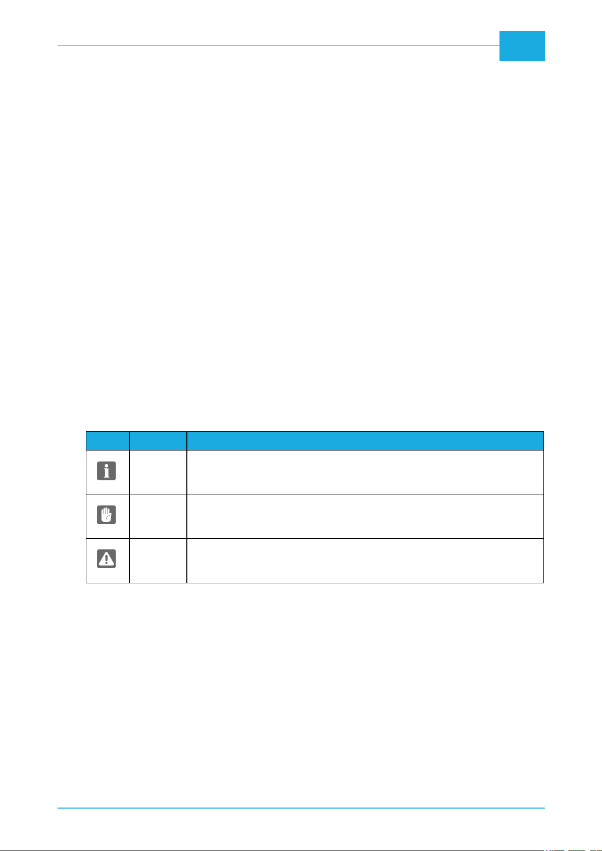
Symbol Meaning Explanation
NOTE
The operator should observe and/or act according to the information in order to
obtain the best possible function of the equipment.
CAUTION
The operator must observe and/or act according to the information in order to
avoid any mechanical or electrical damage to the equipment.
WARNING
The operator must observe and/or act according to the information in order to
avoid any personal injury.
May, 2022 Pre-installation Guide|Flex-i-Line 520 (XP) Dry/Compact/Standard/Max

Pre-installation Guide |Flex-i-Line 520 (XP) Dry/Compact/Standard/Max May, 2022

Transportation 7
Transportation
When the equipment arrives
Storing of the equipment prior to the installation
The equipment will usually be delivered some time before the arrival of the service technician. Provide for
an appropriate place indoor to store the crated equipment until the service technician arrives.
The crate
Checking the crate for damage
Check if the crate is damaged on delivery at the customer's address. Make notes of any damages, before
opening the crate. Provide a detailed description and take a photograph of the damage.
Report any damage of the crate to the shipping company and notify the insurance agent, if appropriate,
before the mishandled package is opened.
Check the Tilt watch and the Shock watch label that the red mark has not appeared and compare their
serial numbers with those on the box label whether they match.
Handling the crate
The icons on the crate indicate how to handle the crate during transport and storage:
May, 2022 Pre-installation Guide|Flex-i-Line 520 (XP) Dry/Compact/Standard/Max

8Transportation
Crate dimensions
Configuration:
Processor
520
Processor
520 XP Tower1 Elevator Tower2
Standard/Max ● ● ● ●
Compact/Dry ● ● ●
Processor 520 Processor 520 XP
L3000 mm (118.1") 4380 mm (172.4")
W2320 mm (91.3") 2320 mm (91.3")
H2000 mm (78.7") 2000 mm (78.7")
Tower 1 Elevator
(Standard/Max)
Elevator
(Compact/Dry) Tower 2
L2720 mm (107.1") 2270 mm (89.4") 2720 mm (107.1") 2570 mm (101.2")
W2300 mm (90.6") 2300 mm (90.6") 2300 mm (90.6") 2300 mm (90.6")
H2480 mm (97.6") 2480 mm (97.6") 2480 mm (97.6") 2480 mm (97.6")
Weights
Equipment only Equipment with crate
Processor 520 1800 kg (3970 lbs) 2050 kg (4520 lbs)
Processor 520 XP 2400 kg (5290 lbs) 2940 kg (6480 lbs)
Tower 1 1900 kg (4190 lbs) 2350 kg (5180 lbs)
Pre-installation Guide |Flex-i-Line 520 (XP) Dry/Compact/Standard/Max May, 2022

Transportation 9
Equipment only Equipment with crate
Elevator (Standard/Max) 1860 kg (4100 lbs) 2250 kg (4960 lbs)
Elevator (Compact/Dry) 1900 kg (4190 lbs) 2300 kg (5070 lbs)
Tower 2 1400 kg (3090 lbs) 1800 kg (3970 lbs)
Tower 2 Max 2000 kg (4410 lbs) 2400 kg (5290 lbs)
May, 2022 Pre-installation Guide|Flex-i-Line 520 (XP) Dry/Compact/Standard/Max

10 Transportation
Lifting the crate
The equipment is supplied in a wooden crate on a pallet.
A forklift truck is required for lifting the crate on arrival and for lifting the equipment off the pallet.
WARNING: The equipment is very heavy equipment.
It is only possible to lift the equipment off the pallet using a forklift truck or a pallet mover.
CAUTION: Make sure to provide a forklift designed and adequate for lifting a crate of the size and
weight as specified in this manual.
Pre-installation Guide |Flex-i-Line 520 (XP) Dry/Compact/Standard/Max May, 2022

Transportation 11
Required width of passage and doorways
Depending on the width of the passage- and doorways through which the equipment has to be transported
to the installation site, the service technician may have to perform the actions described in the table below:
If width of the doorway
is… Then…
More than 2400 mm
(94.5")
The crated equipment can be transported immediately to
the installation site.
CAUTION: May require machine moving skates
suitable for transport of very heavy equipment.
Less than
but
more than
2400 mm
(94.5")
2200 mm
(86.6")
The Service Technician has to unpack the equipment.
CAUTION: May require machine moving skates
suitable for transport of very heavy equipment.
May, 2022 Pre-installation Guide|Flex-i-Line 520 (XP) Dry/Compact/Standard/Max

Pre-installation Guide |Flex-i-Line 520 (XP) Dry/Compact/Standard/Max May, 2022

Installation requirements 13
Installation requirements
WARNING: The equipment must be installed in restricted access locations only.
NOTE: Check the delivery route to the installation location for necessary clearance and remove all
obstructions.
Heating and ventilation
Provide a heat and ventilation system capable of maintaining room temperature between 17°C (63°F) and
25°C (77°F) and a relative humidity (non condensing) of min. 40% and max. 60%.
For heat emission see "Power consumption" on page1.
Installation kit
Installation kit is included with the equipment. It comprise the parts necessary to make the installation.
Ord. code Name Quantity
10104022 FRESH, SOLVENT, LEVEL, SENSOR, COMPLETE 1 pc
10066844 CASTROL SPHEEROL 4601 GREASE 1 pc
10104023 DIRTY, SOLVENT, LEVEL, SENSOR, COMPLETE 1 pc
10104014 CABLE, EXT, PUMP, CONTROL, FLEX-i-PRO 1 pc
0-BA-057 SA, INLET, SOLVENT, EXTERNAL, BARREL 1 pc
0-BA-058 SA, OUTLET, SOLVENT, EXTERNAL, BARREL 1 pc
5-DP-003 KEY LOCK TRIANGLE 1 pc
5-FA-027 HOSE, AIR EXHAUST D140 5 m
5-FA-021 TUBE, POLYURETHANE D4 × 6 5 m
7-HA-010 HOSECLAMP 122-142 2 pcs
1-330-029 SAFETY TANK 1 pc
10103482 SA, OUTLET, SOLVENT, EXT, LINK 1 pc
Floor stability
WARNING: Note the very heavy weight of the equipment!
Please refer to weight and dimensions of the equipment when calculating footprint and load for
preparation of the installation site.
The floor should have a variation in height of no more than 6 mm per meter (1/4” over 40” length). If in doubt
about the floor loading, please consult a structural engineer.
May, 2022 Pre-installation Guide|Flex-i-Line 520 (XP) Dry/Compact/Standard/Max

14 Installation requirements
Space requirements
Free space around the equipment
Decide for a proper installation site for the equipment and make sure that the free space around the
equipment makes servicing possible.
The recommended minimum free space around the equipment is specified in the next illustration.
Pre-installation Guide |Flex-i-Line 520 (XP) Dry/Compact/Standard/Max May, 2022

Installation requirements 15
Dimensions and connections
May, 2022 Pre-installation Guide|Flex-i-Line 520 (XP) Dry/Compact/Standard/Max

16 Installation requirements
Standard/Max
Compact/Dry
Pre-installation Guide |Flex-i-Line 520 (XP) Dry/Compact/Standard/Max May, 2022

Installation requirements 17
Compressed air
Description Value
Min. pressure 6 bar (87 psi)
Max. pressure 10 bar (145 psi)
Volume 100 Nl/min
Hose size ø 6 mm
Solvent connection
Provide a solvent connection for a ø 20 mm diameter hose, which is located no more than 5 meters from
machine connections.
CAUTION: Always check if there is some air in the solvent system. The solvent distribution
system must not contain any air bubbles.
If the solvent barrels are more than 5 meters from the processor and the piping is lifted higher than the
solvent tanks, it is recommended to mount a non-return valve at the barrels to prevent back flow of solvent
or air in the hoses during process. Also use an auxiliary pump.
In case of need to turn off the solvent supply to the processor, it is recommended to install hand valves in
the end of the solvent installation.
CAUTION: Never lead solvent into a drain, as most solvents are strong pollutants. It is also illegal
to empty these types of chemicals into the public sewer system.
Under all circumstances local regulations applying to the treatment of chemical waste must be
followed strictly.
Exhaust connection
Processor exhaust must be connected to the appropriate location (directly to the outside). If the length of
the exhaust hose to the outside is more then 5 meters you have to add an external exhaust pump. Don't
use sharp 90 degrees bends but soft bends.
Dryer exhaust must be connected to the appropriate location (directly to the outside).
Light finisher exhaust must be connected to the appropriate and separate location (directly to the outside).
WARNING: Do not connect the dryer and light finisher exhausts together as the mixing of vapors
could create explosive fumes emission depending of the solvent used to wash the plates.
Make sure that the airflow is correct and minimum exhaust capacity is according to the Exhaust
specification table.
Minimum flow rate
Dryer, min. 600 m³/h (353 ft³/min)
Processor, min. 600 m³/h (353 ft³/min)
Light finisher (each), min. 600 m³/h (353 ft³/min)
May, 2022 Pre-installation Guide|Flex-i-Line 520 (XP) Dry/Compact/Standard/Max

18 Installation requirements
Electrical requirements
Main power outlet
Provide an mains power-outlet with an electrical plug lockout close to the installation site. The table
showing "Power supply requirements" on the facing page indicates the applicable power supply types.
WARNING: Electrical installation, all cabling and cabling connections, fusing and isolation must
conform to local and/or national regulations and guidelines.
WARNING
HIGH LEAKAGE CURRENT
EARTH CONNECTION ESSENTIAL
BEFORE CONNECTING SUPPLY
AVERTISSEMENT
COURANT DE FUITE ÉLÉVE
RACCORDEMENT Á LA TERRE INDISPENSABLE
AVANT DE RACCORDEMENT AU RÉSEAU
Power cable
NOTE: The cable for the main power connection is included with the equipment.
WARNING: The equipment is Class 1 equipment. Therefore, the equipment must be connected to
earth to avoid electrical shocks.
Please be aware of double pole/neutral fusing.
CAUTION:
The conductors in the power supply cable should be of copper.
Provide for additional cable protection, e.g. cable covers, if cable is exposed to heavier transport
such as fork-lift trucks etc.
WARNING: Connection to mains shall be permanent connection.
Connection via wall plug isn't allowed.
Pre-installation Guide |Flex-i-Line 520 (XP) Dry/Compact/Standard/Max May, 2022

Installation requirements 19
Electrical specifications
Power supply requirements
CAUTION: The requirements below are specifications for preparing the installation protection.
The fuses/circuit breakers must be prepared according to local regulations, and with adequate
capacity as specified here. The circuit breakers must be suitable for inventor operation.
NOTE: Specifications on the equipment's name plate is the actual input current and will thus not be
identical to below mentioned.
Supply *
EUR 3W + N + PE,
400 VAC, 50/60 Hz
Fused by 3 × 40 Amps
Cable type: Min. 5 × 16 mm², type H07 RNF
*) Voltage tolerance ± 10%
NOTE: The power cable(s) must be in accordance with local regulations.
WARNING: Please be aware of double pole/neutral fusing.
CAUTION: The fuses must have a breaking capacity of min. 100 kA.
CAUTION: If a circuit breaker of type ELCB, RCCB, or GFCI is used where leakage to ground is
detected, the trip sensitivity must be 300 mA.
Power consumption
Dry Compact Standard Max
In operate, per phase
(±10%), max.
35000 W (119400
BTU)
37500 W (128000
BTU)
40000 W (136500
BTU)
45000 W (153500
BTU)
May, 2022 Pre-installation Guide|Flex-i-Line 520 (XP) Dry/Compact/Standard/Max

Pre-installation Guide |Flex-i-Line 520 (XP) Dry/Compact/Standard/Max May, 2022
This manual suits for next models
1
Table of contents
Other Glunz & Jensen Industrial Equipment manuals
Popular Industrial Equipment manuals by other brands

Kobelt
Kobelt 7174 Owner's Operation, Installation & Maintenance Manual

Sullair
Sullair 65 II Use and Maintenance Spare Parts List

Siemens
Siemens 3TL81 operating instructions

BSS Audio
BSS Audio BOSS I Series instruction manual

Meler
Meler MICRON+ GEAR Series instruction manual

LNS
LNS Hydrobar Express 332 Startup manual