Novexx Solutions EIDOS XTO Series User manual

User Manual XTO intermittent series
Edition C - 01/2024
Original Instructions - keep for future reference
RT805
USER MANUAL
XTO2i.20 / XTO2i.40 / XTO2i.60
XTO22i.40 / XTO22i.60 / XTO22i.90
Intermittent Thermal Transfer Overprinter
(TTO)
This manual contains the EC Declaration of Conformity


User Manual XTO intermittent series
Edition C - 01/2024
1
Contents
Contents
Information ................................................................................................................................ 2
NOTES ON THE CORRECT USE OF THE PRINTER ..............................................................................2
GENERAL NOTES...............................................................................................................................2
SAFETY NOTICES...............................................................................................................................3
GENERAL PRECAUTIONS ..................................................................................................................3
DANGEROUS AREAS ON THE PRINTING UNIT..................................................................................4
PROTECTION ELEMENTS PROVIDED ON THE PRINTER ....................................................................8
Product Description ................................................................................................................. 13
FUNCTIONALITY .............................................................................................................................13
PECULIARITY ...................................................................................................................................13
CARRIAGE STROKE LENGTHS AND MACHINE TYPE........................................................................14
SYSTEM MODELS............................................................................................................................15
REAR CONNECTION PANEL ............................................................................................................19
OPERATING PANEL.........................................................................................................................20
BASIC SETTINGS..............................................................................................................................23
Operation ................................................................................................................................ 30
INSERTING CONSUMABLES ............................................................................................................30
THE THERMAL RIBBONS .................................................................................................................31
PRINTING........................................................................................................................................32
CREATION AND SENDING OF THE LABEL WITH EASYCODE ...........................................................33
HOW TO STORE LABEL FILES (.LM1)...............................................................................................35
HOW TO BACK UP ..........................................................................................................................35
SETTING AND MONITORING ..........................................................................................................36
STATUS MESSAGES.........................................................................................................................58
Multipitch motorized positioner ............................................................................................... 60
DEVICE MANAGEMENT..................................................................................................................61
Preventive Maintenance .......................................................................................................... 64
CLEANING INSTRUCTIONS..............................................................................................................64
CLEANING THE PRINT HEAD...........................................................................................................65
CLEANING THE PRINTING PLATE....................................................................................................65
CLEANING ROLLS AND RIBBON PASSAGES ....................................................................................66
CLEANING THE CARRIAGE SLIDING GUIDE.....................................................................................67
Appendix 1 ............................................................................................................................... 68
EC DECLARATION OF CONFORMITY...............................................................................................68
Appendix 2 ............................................................................................................................... 69
CE LABEL.........................................................................................................................................69
Appendix 3 ............................................................................................................................... 70
ZEBRA and EIDOS NICELABEL EMULATION FILE MANAGEMENT (.prn, .zpl) .................................70

User Manual XTO intermittent series
Edition C - 01/2024
2
Information
Information
NOTES ON THE CORRECT USE OF THE PRINTER
Read these notes together with Chapter “Safety notices" to ensure that the printer is used correctly.
Switching on the printer.
•If the printer has been left in a cold or excessively hot environment for a considerable time, wait
at least 1 hour before switching it on to prevent humidity collecting on the internal circuits.
•After switching off, wait for a few seconds before switching on the printer again.
Use in particularly places
If the printer is going to be used in particularly humid conditions (for example cheese factories) the
protection kits are necessary. Do not use it where there is a lot of oil, iron particles, or dust.
Disposal
The device may not be disposed of with household rubbish. This appliance is labelled in
accordance with European Directive 2012/19/UE concerning used electrical and
electronic appliances (waste electrical and electronic equipment - WEEE).
The guideline determines the framework for the return and recycling of used appliances
as applicable throughout the EU. To return your used device, please use the return and
collection systems available to you.
GENERAL NOTES
Validity of this manual and required compliance
This user manual refers exclusively to the electronic printer for thermal transfer to film named XTO.
It is used for proper operation and adjustment of the printer.
The printer must be properly installed and configured to allow for operation and settings.
For information about installation and maintenance, see the Installation manual.
For technical questions not covered in this operating manual request a service technician.
Technical release
Software version XTO: 2.9
Hardware version XTO: 68XTO2I20E, 68XTO2I40E, 68XTO2I60E
68XTO22I40B, 68XTO22I60B, 68XTO22I90C
These instructions have to be kept for future reference and must be
available throughout the expected life of the product.
Liability and Copyright
All rights to this manual are reserved. This manual may not be reproduced in any form, either wholly
or partially, without the express written authorisation of Eidos Srl. The contents of this manual are
subject to modifications and improvements without prior warning. Every effort has been made to
ensure the accuracy of the contents. If errors and/or inaccuracies are detected, inform Eidos Srl in
order to make the manual as exhaustive as possible. Eidos Srl accepts no responsibility for any
accidental errors or for any damage arising from the supply, scope or use of this manual.

User Manual XTO intermittent series
Edition C - 01/2024
3
Information
How information is represented
Explanation of symbols
WARNING!
A warning symbol refers to risks that can result in severe or fatal injuries! The text
within this area contains instructions for preventing damage.
➔
Instructions must be followed without exception.
WARNING! The text within this area contains important recommendations as well as additional
information or information to use the product correctly and efficiently.
SAFETY NOTICES
The printer is provided with a “EC Declaration of conformity” according to the "Machinery Directive
2006/42/EC" which includes the reference standards for "Electromagnetic Compatibility" and
"Electrical Safety":
1.
Do not start up the machine without first reading and implementing the prescriptions of the
“USER MANUAL” and the present “SAFETY NOTICES”.
2.
The printing unit is equipped with two covers: the first [RM1] is removable while the second
[RM2] can be opened by rotating it on two hinges. The removable cover [RM1] is monitored
by two sensors [SENS_C1] and [SENS4] which switch off the power supply to the motors when
the cover is open. The presence of a mechanical interlock [IB1] does not allow you to open
the cover [RM2] without first removing the cover [RM1] and it does not allow you to insert
and close the cover [RM1] before closing the cover [RM2]. To prevent finger access in the
carriage [C1/C2] movement area [A/B], the XTO print unit and the print plate must always be
aligned with each other.
3.
The printer must not be used in an explosive environment or be used to treat explosive
materials.
4.
The printer must not be used in irregular situations such as working without guards being
correctly fitted to the machine; working with products other than those prescribed.
5.
After 7 years of operation on an 8-hour daily shift, a complete overhaul of the product is
recommended.
GENERAL PRECAUTIONS
1.
Be careful when moving or carrying the printer. Wear safety shoes when installing or removing
the printer from the packaging machine: dropping the printer may cause injury or property
damage. The machine must NOT be used by the lid or the handle. (See the "LIFTING AND
TRANSPORT" Chapter of the Technical Manual RT806).
2.
Do not open the printer during printing.
3.
When cleaning the surface of the printer case, do not use the cloth that is soaked in thinner,
trichloroethylene, benzine, ketone or similar chemicals.
4.
Do not spill liquids or spray insecticide on the printer.
5.
When printer trouble occurs, do not try to dissemble it. Instead, consult our service personnel.

User Manual XTO intermittent series
Edition C - 01/2024
4
Information
DANGEROUS AREAS ON THE PRINTING UNIT
Dangerous areas on XTO2i.nn - front and bottom view
Note:
During the installation it is necessary to fix the printing plate and the
printing unit so that the plate prevents finger access to the areas [A] and [B]
where the carriage with the print head moves.
Figure 1: dangerous areas on XTO2i.nn - front viewl
Figure 2: dangerous areas on XTO2i.nn – bottom viewl
s2
s1
S
H
T
t
X
Y
A
B
[RM1]
[RM2]
[C1]

User Manual XTO intermittent series
Edition C - 01/2024
5
Information
Dangerous areas on XTO22i.nn (model with double carriage) - front and bottom view
Note:
During the installation it is necessary to fix the printing plate and the
printing unit so that the plate prevents finger access to the areas [A] and [B]
where the carriage with the print head moves.
Figure 3: dangerous areas on XTO22i.nn - front view
Figure 4: dangerous areas on XTO22i.nn – bottom view
s2
s1
S
H
T
t
S
H
T
t
A
B
[RM1]
[RM2]
[C1]
[C2]
B
[C2]
[C1]
A

User Manual XTO intermittent series
Edition C - 01/2024
6
Information
Dangerous areas - rear view
Dangerous areas on - side views
Dangerous areas - carriage.
Figure 5: Dangerous areas - rear view
W
P
Figure 6: Dangerous areas - side views
Figure 7: Dangerous areas - carriage
M2
M3
M1
Y
U
P
X
Ct
Sm
t

User Manual XTO intermittent series
Edition C - 01/2024
7
Information
Passive (non-motorized) rotating rollers
Definitions
H
Movement of the carriage during printing or positioning in the "Service" area.
Danger of crushing the fingers
S
Movement of the carriage when returning to Home after printing or during a return from
"Service". Danger of crushing the fingers.
A
Access from the lower right side: carriage moving to the right (home position return)
B
Access from the lower left side: carriage moving to the left (print)
T
Movement of the print head
s1
Rotation of the mandrel holding the ribbon release coil
s2
Rotation of the mandrel holding the ribbon rewinding coil
X
Movement of the carriage during printing or positioning in the "Service" area.
Danger of crushing the fingers.
Y
Movement of the carriage when returning to Home after printing or during a return from
"Service". Danger of crushing the fingers.
P
Rotation movement of the pulley and the belt for transmitting motion to the carriage
W
Rotation movement of the pulley and the belt for transmitting motion to the carriage
Ct
Print head movement servomotor cam
R1
Rubberized ribbon encoder roller
R2…7
Free rollers for ribbon guide
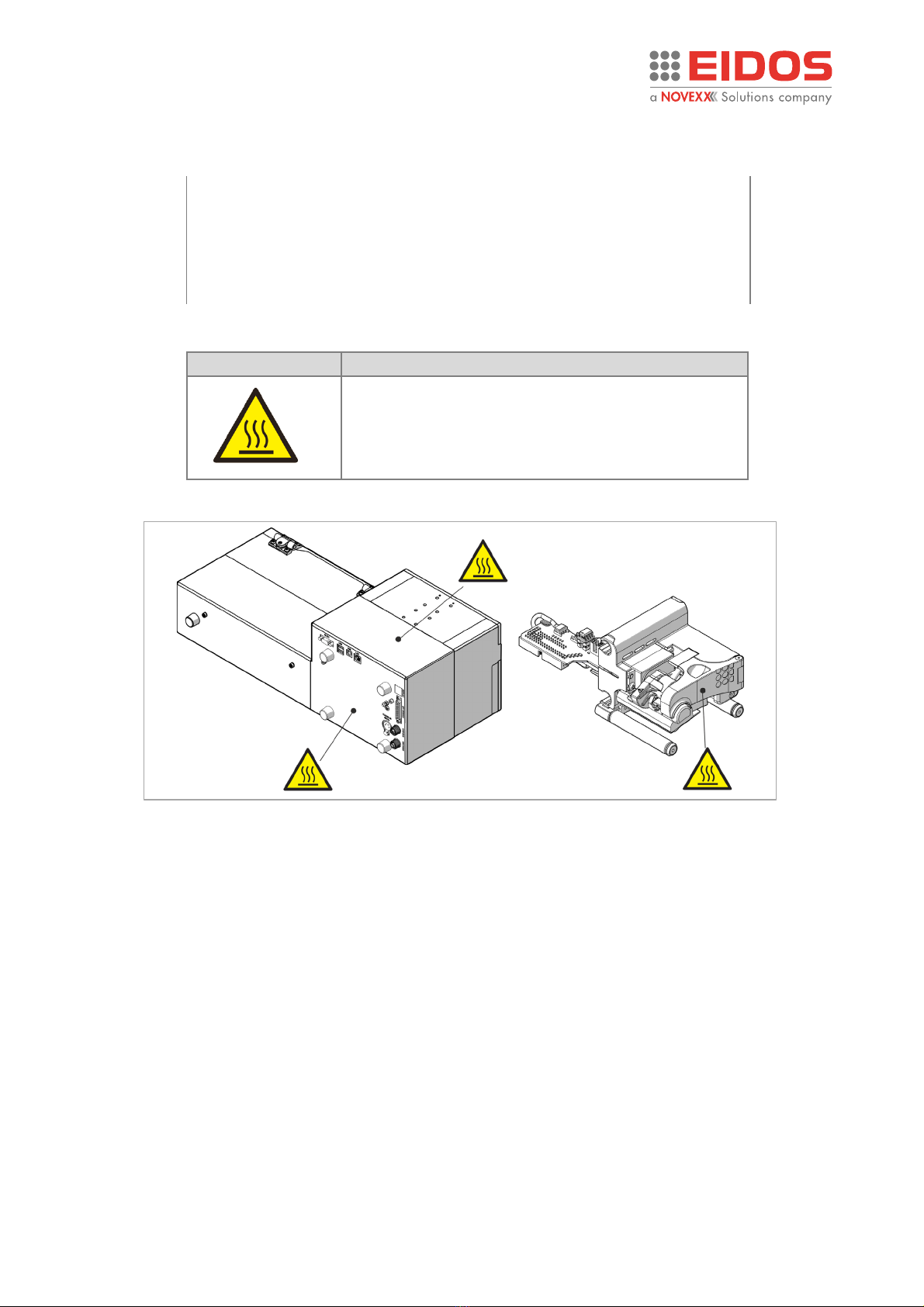
Hot parts highlight on XTO:
Part temperatures were measured at ambient temperatures of 20 ° C and after the XTO ran at
full cadence for 7 hours.
M1
Ribbon unwinding motor body
T max. 45°C
M2
Ribbon rewinding motor body
T max. 50°C
M3
Carriage movement motor body
T max. 60°C
U
CPU Heatsink
T max. 50°C
t
Print head
T max. 60°C
sm
Print head motion servo motor body
T max. 55°C
Figure 8: free rollers
R1
R2
R3
R4
R6
R7
R5
R3
R4
for
XTO22
i.nn only

User Manual XTO intermittent series
Edition C - 01/2024
8
Information
PROTECTION ELEMENTS PROVIDED ON THE PRINTER
Covers fixed with screws
WARNING!
Disconnect the 48Vdc power supply to the printer before removing the fixed guards
[RF1], [RF2], [RF3a], [RF3b]. The fixed guards must be removed only for extraordinary
maintenance or repairs.
Movable interlocked guard [RM1] and openable guard [RM2]
Figure 9: fixed cover
Figure 10: movable interlocked guard and openable guard
RM1
RM2
RF3a
RF2
RF1
RF3b

User Manual XTO intermittent series
Edition C - 01/2024
9
Information
Fixed guard but not solidly screwed to the Printing Unit:
The Printing Plate [PP] cannot be strongly screwed to the Printing Unit [PU] because it is necessary
to leave the passage to the packaging film [PF] to be printed.
Note:
During the installation it is necessary to fix the printing plate [PP] and the
printing unit [PU] so that the plate prevents finger access to the areas [A]
and [B] (Figure 2-Figure 4) where the carriage with the print head moves.
On supports where there is an independent adjustment of the Printing Unit [PU] and the Printing
Plate [PP], it is always necessary to maintain a relative position between the two parts that prevents
access to dangerous areas. Also to obtain a good print quality, the print head must be positioned at
a distance from the edge of the rubber layer, not less than 5 mm and that the Printing Plate [PP] is
always centred with respect to the Printing Unit [PU].
[PU]
[PF]
[PP]
Figure 11: Printing plate
Figure 12: Printing plate and Print Unit position

User Manual XTO intermittent series
Edition C - 01/2024
10
Information
Monitoring sensors movable guard [RM1] inserted
Figure 14: monitoring sensors
Figure 13: printing plate alignment
SENS4
SENS_C1
Magnetic sensor
IB1*
Mechanical interlock
*ATTENTION: in case of
breakage of the IB1 block, it
will be necessary to replace
the opening cover, otherwise
the printer will be NOT safe.

User Manual XTO intermittent series
Edition C - 01/2024
11
Information
External safety contacts: SAFETY_A and SAFETY_B (SAF_EXT)
NOTE: If not used, they must be jumpered.
Not interlocked movable guard [RM3]
The guard is accessible only after removing the interlocked mobile guard [RM1].
Magnets and magnets ring
To ensure good fastening of the movable guard [RM1] to the printing unit, magnets [mg1], [mg2]
have been provided on the printer body and magnetic rings [am1], [am2] on the ribbon inserter.
Figure 15: safety contacts
[SAF_EXT]
SAFETY_A
SAFETY_B
SAFETY_SAF
Figure 16: guard - in figure the XTO22i.nn with double carriage
mg2
am2
mg1
am1
Figure 17: magnets
RM3
User Manual XTO intermittent series
Edition C - 01/2024
12
Information
Warning symbols on the machine
CAUTION!
Warning symbols on the machine provide important information for the
operating personnel.
➔Do not remove warning symbols.
➔Replace missing or illegible warning symbols.
Meaning of the warning symbols:
Warning symbol
Meaning
The "Hot surface" symbol informs the operator and
the staff assigned to the
maintenance of the
presence of potentially dangerous hot surfaces.
Allow the device to cool off before touching it.
Figure 18: warning symbols

User Manual XTO intermittent series
Edition C - 01/2024
13
Product DESCRIPTION
Product Description
FUNCTIONALITY
The XTO intermittent is an electronic printer for "thermal transfer to film" that is able to write
automatically and directly on the plastic or paper film used in packaging machines by means of an
inked thermal ribbon. The packaging film must be stationary during printing.
The XTO intermittent codes the different production batches with variable text, barcodes and logos
extremely flexibly, ensuring high quality and fast printing.
In stand-alone operation, the label files created with the EASYCODE program installed in a PC can
be loaded in the printer using the USB memory key.
With the XTO22i.nn model, with double carriage, it is possible to halve the printing time and
considerably increase the operating speed. It is also possible to manage and print different print
formats and texts for each of the two printheads.
PECULIARITY
•Print Unit very light and compact, easy to be installed.
•Easy to service and repair; easy system of ribbon passage for changing operation.
•Programmable printing steps and format printing parameters loadable by the touch screen
display (optional) or the P.C. through the use of a browser (Chrome, Edge ...).
•Improve unit uptime: not necessary to uninstall the print unit from the line.
•Modular assembly: mechanic + electronic.
•Easy and fast replacement of electronic components (no interference with mechanical parts).
•HMI (Human-Machine Interface) user friendly.
•Simply ribbon changing operation.
•Simply print head and print plate cleaning and replacing directly on board the printer.
•Printer management (parameters, labels, diagnostic etc..) with local EIDOS Touch panel or
remote PC with a Web Browser.

User Manual XTO intermittent series
Edition C - 01/2024
14
Product DESCRIPTION
CARRIAGE STROKE LENGTHS AND MACHINE TYPE
XTO model
Carriage stroke [C]
Print head type
The maximum print length (carriage stroke
length) is autodetected when the printer is
switched on.
XTO2i.20
200 mm
53 mm
XTO2i.40
400 mm
53 mm
XTO2i.60
600 mm
53 mm
Distance between the two print heads [C1]
XTO model
Carriages stroke [C1+C2]
Print head type
Minimum
Maximum
XTO22i.40
400 mm
2 x 53 mm
180 mm
350 mm
XTO22i.60
600 mm
2 x 53 mm
250 mm
550 mm
XTO22i.90
900 mm
2 x 53 mm
350 mm
850 mm
The “XTO model” is shown on the red bar of the Help page.
The Printer is available as right hand (RH) version, i.e. printing occurs when the carriage moves from
left (home position) to right.
Figure 20: printer model
Figure 19: film passage and carriage stroke length
S00074

User Manual XTO intermittent series
Edition C - 01/2024
15
Product DESCRIPTION
SYSTEM MODELS
WARNING!** the 45CV914/1 cable is supplied 7 meters long, but during installation
it must be cut as short as possible, to avoid the error signalling (E207) when closing
the front cover. The cable must pass far from the cables that supply motors or
electrovalves, to avoid noises and spikes.
Note: The I/O SIGNALS Junction Box 49KS0162 is not intended for Industrial use.
Figure 21: XTO2i.nn system models
(capacitor kit to be connected
on the 48Vdc power supply
V+/V- output pins)
2 m
2 m
*nn = Carriage length (in cm) identifier
XTO
49KS0162
+
XTO
49KS0162
+
XTO
49KS0162
+
XTO
49KS0162
+
7XTO2Inn-2
7XTO2Inn*-1
7XTO2Inn-3
7XTO2Inn-4
45CV910/1
(capacitor kit to be connected
on the 48Vdc power supply
V+/V- output pins)
45CV910/1
45CV914/1
+48Vdc 220W
L = 7 m**
45CV914/1
+48Vdc 220W
L = 7 m**
2 m
2 m

User Manual XTO intermittent series
Edition C - 01/2024
16
Product DESCRIPTION
WARNING! *** the 45CV914/1 cable is supplied 7 meters long, but during
installation it must be cut as short as possible, to avoid the error signalling (E207)
when closing the front cover. The cable must pass far from the cables that supply
motors or electrovalves, to avoid noises and spikes.
Note: The I/O SIGNALS Junction Box 49KS0162 is not intended for Industrial use.
45CV932/1 + CE300434
45CV914/1
XTO
49KS0162
+
XTO
49KS0162
+
XTO
49KS0162
+
+48Vdc 320W
L = 7 m**
XTO
49KS0162
+
7XTO22Inn-2
7XTO22Inn*-1
7XTO22Inn-3
7XTO22Inn-4
45CV910/1
(capacitor kit to be connected
on the 48Vdc power supply
V+/V- output pins)
45CV910/1
Figure 22: XTO22i.nn system models
45CV932/1 + CE300434
45CV914/1
+48Vdc 320W
L = 7 m**
(capacitor kit to be connected
on the 48Vdc power supply
V+/V- output pins)
*nn = Carriage length (in cm) identifier
2 m
2 m

User Manual XTO intermittent series
Edition C - 01/2024
17
Product DESCRIPTION
IP Version: 7XTO2Inn*-1TR, 7XTO22Inn*-1TR / 7XTO2Inn-1IP, 7XTO22Inn-1IP
The TR printer version offers an IP30 protection degree, having electronic boards and print head
tropicalized. An IP printer version is available, with IP33 protection degree. It is equipped with
tropicalized electronic boards and print head, as well as a rear cover with adequate protection for
the connectors.
The optional 53SDK20 touch panel offers IP55 protection. An IP version of the Touch Panel, code
53SDK21, is also available, to be installed on the electrical cabinet of the packaging machine (a hole
is required).
Figure 23: IP model
Figure 24: IP protected components
L = 7 m***
Touch panel
53SDK20
Touch panel
53SDK21
Rear cover
with IP
33
protection and
angled connectors
(for
-IP model only)
Tropicalized
interface board
Tropicalized
CPU board
Tropicalized
Power board
Tropicalized
Led board
Tropicalized
carriage board
Tropicalized
Cryptomemory
Tropicalized
encoder board
Tropicalized
print head
USB port
XTO
45CV914/1
45CV910/1
(capacitor kit to be connected
on the 48Vdc power supply
V+/V- output pins)
*nn = Carriage length (in cm) identifier
** = see note on previous page
***= 320W forr XTO22i.nn
48Vdc-220W
48Vdc
-320W***

User Manual XTO intermittent series
Edition C - 01/2024
18
Product DESCRIPTION
53SDK21 Touch panel
It is a 7 "TFT color graphic display with capacitive touch connected via ethernet to the printer, from
which it is also powered.
To fix the EIDOS Touch Panel to the packaging machine, a hole must be made, to be made as per
the drawing below. Fixing is ensured by means of an IP55 protection class sealing gasket. The EIDOS
Touch Panel is therefore also suitable for applications in humid or dusty environments.
Note: The maximum thickness of the plate on which the "EIDOS Touch Panel" can be applied is
4.5 mm
Figure 25: Touch Panel EIDOS 53SDK21
Drilling template
Place the panel, centring it within
the hole on the electrical cabinet of
the packaging machine, by
tightening the metal plate from the
inner side, by means of the screws
and the washers.
This manual suits for next models
6
Table of contents
Other Novexx Solutions Industrial Equipment manuals


