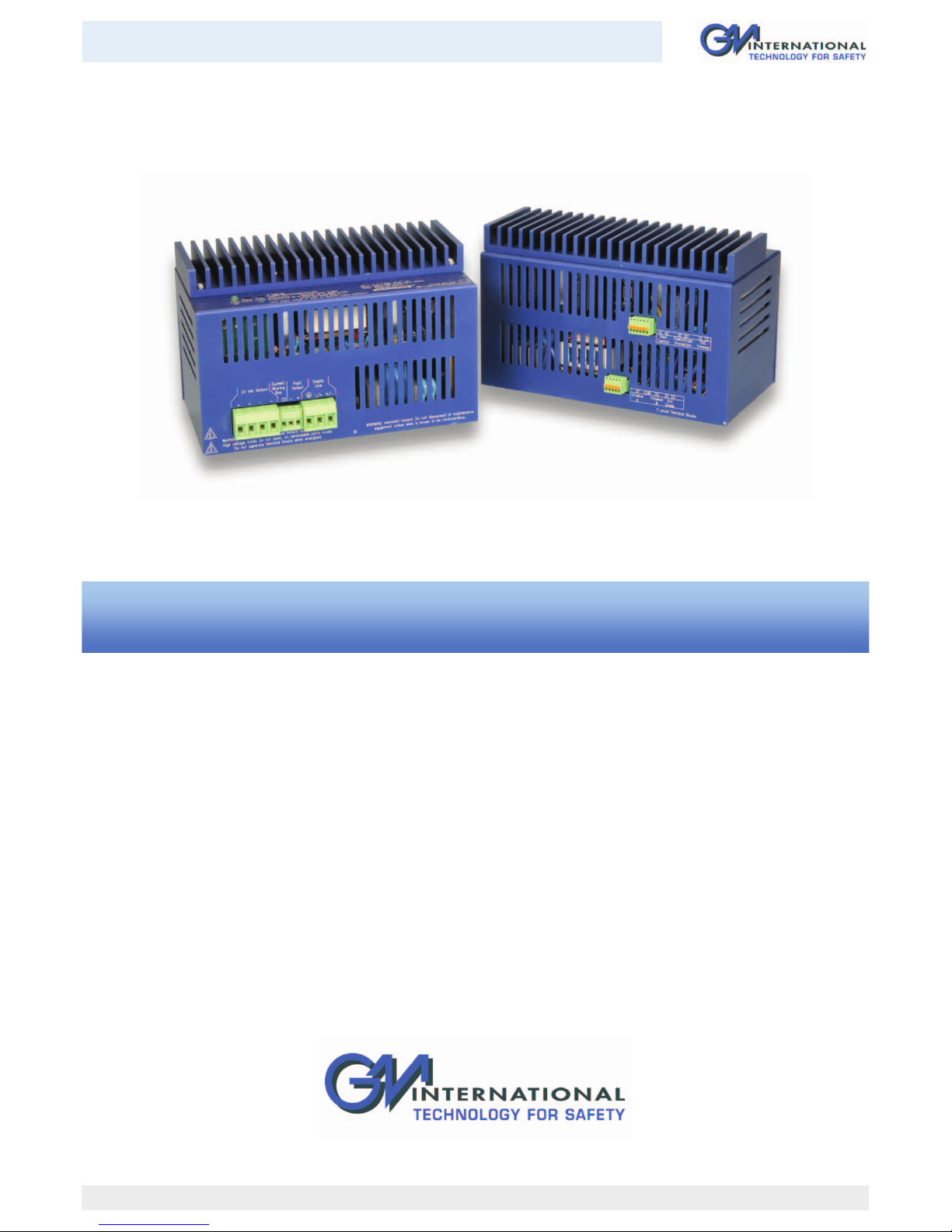
4 PSD1206 - PSD1210 - SIL 3 - SIL 2 Switching Power Supply 24 Vdc G.M. International ISM0076-7
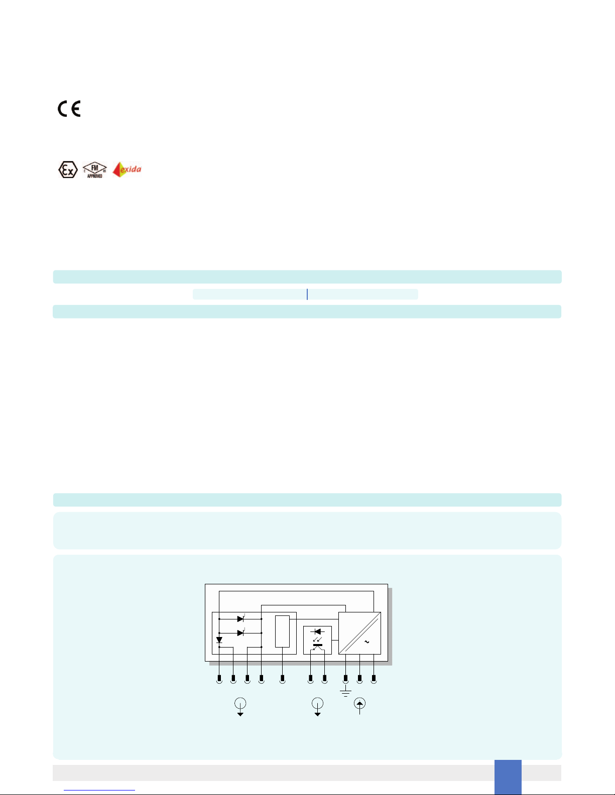
SAFE AREA, ZONE 2 GROUP IIC T4,
NON HAZARDOUS LOCATIONS, CLASS I, DIVISION 2, GROUPS A, B, C, D T-Code T3, CLASS I, ZONE 2, GROUP IIC T3
Function Diagram
Non-incendive field wiring is not recognized by the Canadian Electrical Code, installation is permitted in the US only.
For installation of the unit in a Class I, Division 2 or Class I, Zone 2 location, the wiring between the control equipment and the PSD1206, PSD1210 shall be accomplished via conduit
connections or another acceptable Division 2, Zone 2 wiring method according to the NEC and the CEC.
For Intrinsic Safety application limits the line supply voltage to a maximum of 250 Vrms, not to be connected to control equipment that uses or generates more than
250 Vrms or Vdc with respect to earth ground.
PSD1206, PSD1210 must be installed, operated and maintained only by qualified personnel, in accordance to the relevant national/international installation standards
(e.g. IEC/EN60079-14 Electrical apparatus for explosive gas atmospheres - Part 14: Electrical installations in hazardous areas (other than mines), BS 5345 Pt4, VDE 165, ANSI/ISA
RP12.06.01 Installation of Intrinsically Safe System for Hazardous (Classified) Locations, National Electrical Code NEC ANSI/NFPA 70 Section 504 and 505, and the Canadian Electrical
Code CEC) following the established installation rules.
The power supply must be placed in an enclosure with IP4X protection degree when used in locations providing adequate protection against the entry of solid foreign
objects or water capable of impairing safety, or be placed in an enclosure with IP54 protection degree for other locations.
De-energize main power source (turn off power supply voltage), wait at least 3 minutes to discharge internal capacitors before plug or unplug the terminal blocks when installed in
Hazardous Area/Hazardous Locations or unless area is known to be nonhazardous. Hazardous voltage are present at the input terminal block and inside the unit when connected to the
main supply voltage, do not touch electrical connection and do not put conductive object inside the unit.
Warning: substitution of components may impair Intrinsic Safety and suitability for Division 2, Zone 2.
Explosion Hazard: to prevent ignition of flammable or combustible atmospheres, disconnect power before servicing or unless area is known to be nonhazardous.
Failure to properly installation or use of the equipment may risk to damage the unit or severe personal injury.
The unit has no serviceable parts inside, do not open the enclosure. The unit cannot be repaired by the end user and must be returned to the manufacturer or his authorized
representative, any unauthorized modification must be avoided.
Warning
PSD1206, PSD1210
Power Supply
FM Approved under
non-incendive field wiring
Unclassified Locations or
Hazardous (Classified) Locations
Class I, Division 2, Groups A, B, C, D, T-Code T3
Class I, Zone 2, Group IIC, IIB, IIA, T-Code T3
Hazardous (Classified) Locations
Class I, Division 2, Groups A, B, C, D
Class II, Division 2, Groups E, F, G
Class III, Division 2
Class I, Zone 2, Group IIC, IIB, IIA
FM Approved under non-incendive field
wiring (permitted only for US installations),
UL Listed or third party approval
Non-incendive
Equipment
Unclassified Locations
-24Vdc
+24Vdc+
-
FLT+
L/+
N/-
FLT- -
+
Supply Line
Control
Equipment
Must not use or generate
more than 250 Vrms or Vdc
Storage
If after an incoming inspection the unit is not installed directly on a system (parts for spare or expansion with long storage periods) it must be conveniently stocked. Stocking area
characteristics must comply with the following parameters: Temperature: –20 to +60 °C, the –45 to +80 °C in the data sheet is meant for limited periods, mainly to arrange for air
transport, -10 to +30 °C are preferred. Humidity: 0 to 90 %, long period high humidity affects the package integrity, 0 to 60 % humidity is preferred.
Vibration: no prolonged vibration should be perceivable in the stocking area to avoid loosening of parts or fatigue ruptures of components terminals.
Pollution: presence of pollutant or corrosive gases or vapors must be avoided to prevent corrosion of conductors and degradation of insulating surfaces.
Disposal
The product should not be disposed with other wastes at the end of its working life. It may content hazardous substances for the health and the environment, to prevent possible harm
from uncontrolled waste disposal, please separate this equipment from other types of wastes and recycle it responsibly to promote the sustainable reuse of material resources.
This product should not be mixed with other commercial wastes for disposal.
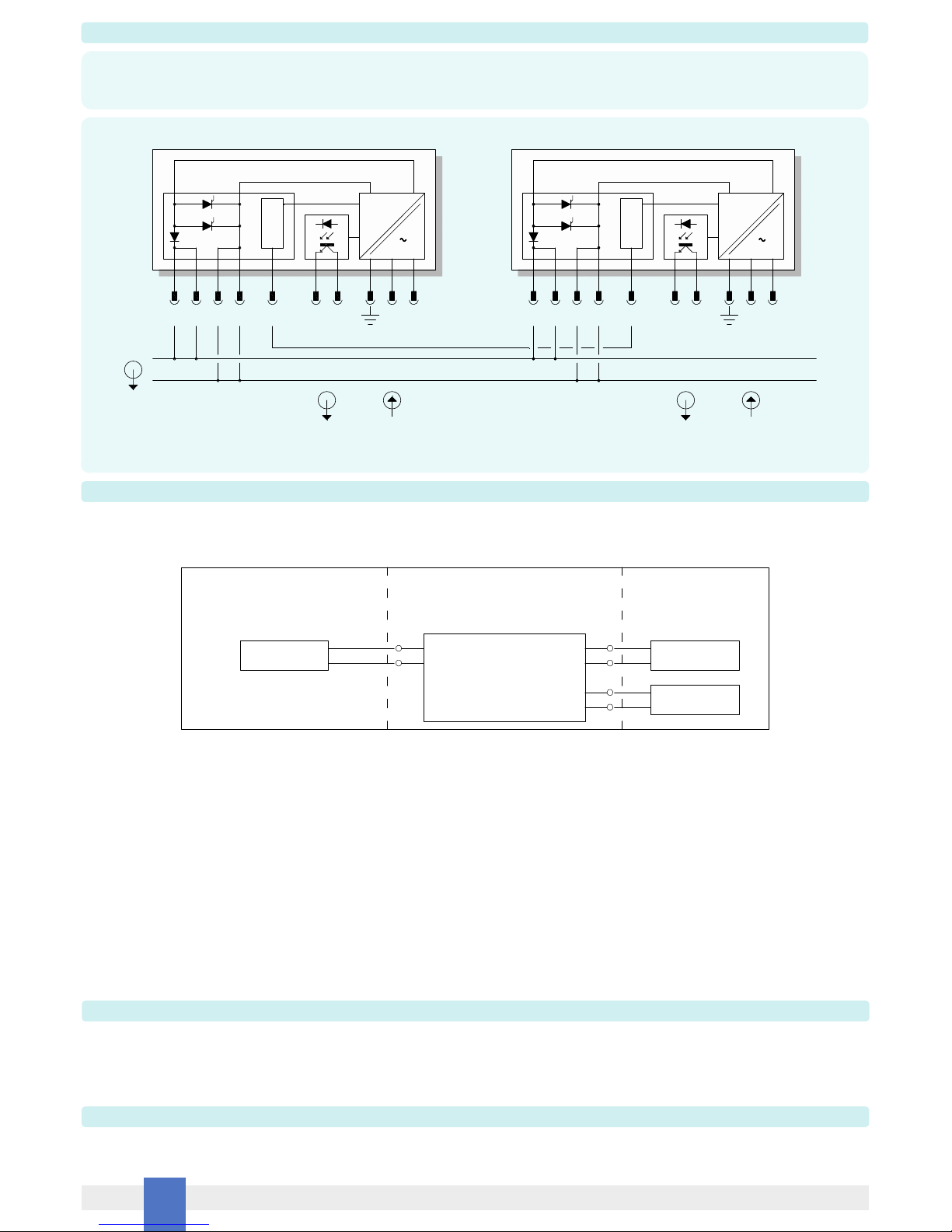
MODELS PSD1206 - PSD1210
++-- -+ L/+N/-
=
_
CS
Current
Sharing
Fault
Output 1
Supply
Input 1
24 Vdc
Output Bus
MODELS PSD1206 - PSD1210
++-- -+ L/+N/-
=
_
CS
Current
Sharing
Fault
Output 2
Supply
Input 2
Connection for current sharing
SIL 3
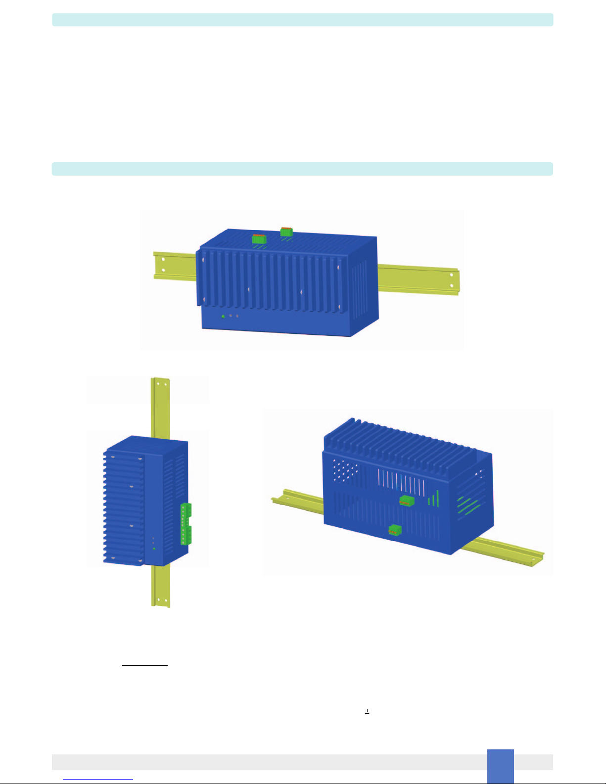
PSD1206 or PSD1210 is an isolated Switching Power Supply unit installed on a standard EN50022 T35 DIN Rail located in Safe Area/Non Hazardous Locations or Zone 2, Group IIC,
Temperature Classification T4, Class I, Division 2, Groups A, B, C, D, Temperature Code T3 and Class I, Zone 2, Group IIC, IIB, IIA Temperature Code T3 Hazardous Area/Hazardous
Locations (according to EN/IEC60079-15, FM Class No.3611, CSA-C22.2 No. 213-M1987, CSA-E60079-15) within the specified operating temperature limits Tamb -20 to +60 °C and
mounting conditions.