GM Pickup GMT900 C User manual

BAER Your Complete Performance Brake Supplier!
Baer, Incorporated 3108 W. Thomas Road, Suite 1201 Phoenix, Arizona 85017
Page 1 of 4
Installation Instructions
Product: Rear GT disc conversion Instruction Part Number: 6000269
Vehicle
Make: GM Pickup
Model: GMT900 C or K10
Year(s): 2005>
Notices – Read and Follow BEFORE ATTEMPTING INSTALLATION
• All installations require proper safety procedures and protective eyewear.
• All installations assume basic mechanical skill and a factory service manual for the vehicle on
which the installation is to be performed.
• All references to LEFT side of vehicle always refer to the Driver’s side of the vehicle.
• Any installation requiring you to remove a wheel or gain access under the vehicle requires use of
jack stands appropriate to the weight of the vehicle. In all cases Baer recommends jack stands
rated for at least 2-tons.
• A selection of hand tools sufficient to engage in the installation of these products is assumed and
is the responsibility of the installer to have in his/her possession prior to beginning this
installation. All installations, which require removal of hydraulic hoses and/or bleeding of the
brakes, require appropriate fitting/line wrenches, as well as a safety catch can and protective
eyewear. Other than these items, if unique or special tools are required they are listed in the
section for that step.
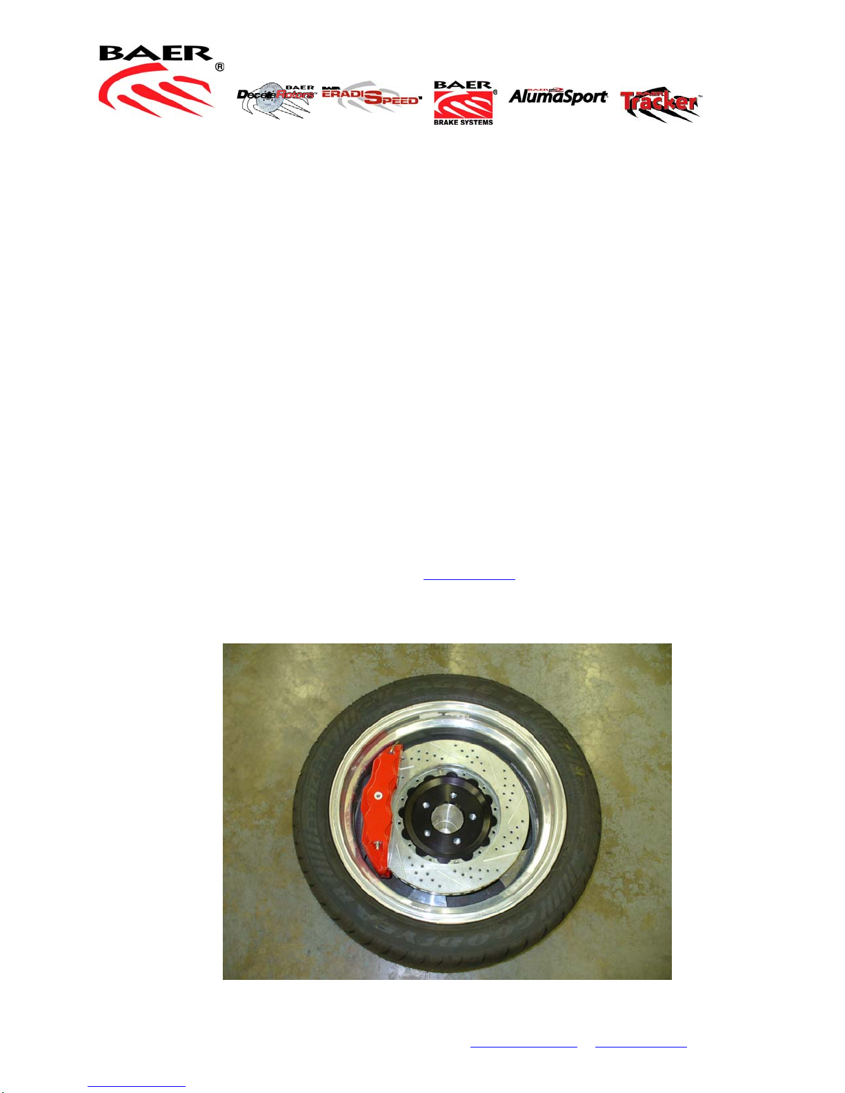
• ALWAYS CONFIRM WHEEL FIT PRIOR TO BEGINNING INSTALLATION OF ANY BRAKE
SYSTEM OR “UPSIZED” ROTOR UPGRADE! In addition to already having checked fit using the
Baer Brake Fit Templates available online at www.baer.com, always place the actual corner
assembly or a combination of the caliper assembly fit onto the rotor into the actual wheel to
reconfirm proper clearance is available between the caliper and the wheel before proceeding with
the actual installation.

BAER Your Complete Performance Brake Supplier!
Baer, Incorporated 3108 W. Thomas Road, Suite 1201 Phoenix, Arizona 85017
Page 2 of 4
• When installing rotors on any Baer Products be sure to follow the direction of rotation indicated on
• A proper professional wheel alignment is required for any system requiring replacement of the
front spindles, or tie rod ends. Follow factory prescribed procedures and specifications unless
otherwise indicated.
• At all times stop the installation if anything is unclear, or the parts require force to install. Consult
directly with Baer Technical Staff in such instances to confirm details. Please have these
instructions, as well as the part number machined on the component that is proving difficult to
install, as well as the make, model, and year (date of vehicle production is preferred) of your
vehicle available when you call. Baer’s Tech Staff is available from 8:30-am to 5-pm Mountain
Standard Time (Arizona does not observe Daylight Savings Time) at 602 233-1411 Monday
through Friday.
Raise the truck and support with appropriate jack stands. Remove the differential cover. Locate and
remove the differential retaining pin. (see photo 1) Slide axles inward and remove c-clips. Slide axles
completely out of the housing using care not to damage axle seals
Photo 1
Disconnect both park brake cables. Disconnect fluid lines from backing plates and cap with supplied vinyl
caps.
the rotor hat area with either
an arrow, or an “L” for left, or
an “R” for right, or both. “L” or
left, always indicates the
driver’s side of US spec
vehicles.
Images shown are “L” left
rotors.

BAER Your Complete Performance Brake Supplier!
Baer, Incorporated 3108 W. Thomas Road, Suite 1201 Phoenix, Arizona 85017
Page 3 of 4
Remove the 4 bolts holding the backing plate to the housing. Retain these bolts for Banksia installation.
Installation note: Both Banksia assemblies are identical. The left side (drivers) caliper will be in the 10
o’clock position with the park actuator at the rear. Right side will be in the 2 o’clock position. Install these
assemblies and torque bolts to 85 ft-lbs. Photo of left side below.
Photo 2
Carefully bend the factory hardlines forward and down as shown in photo 3. This is the right side. Install
the clamp and hose bracket from the Hardline Retainer Assy. Position as shown in photo 3.
Photo 3
Inspect bearings and seals for wear or damage and replace as necessary

BAER Your Complete Performance Brake Supplier!
Baer, Incorporated 3108 W. Thomas Road, Suite 1201 Phoenix, Arizona 85017
Page 4 of 4
Using care not to damage seals, reinstall axles, c-clips, differential pin and pin retainer bolt. Install
differential cover and refill with lubricant.
Install correct side rotor and hold in place with one lug nut. Install caliper, with bleeder screw pointed up,
using supplied 14mm x 35mm bolts. Torque these to 110 ft-lbs.
Install supplied steel braided hose as shown in photo 4, using supplied banjo bolts and copper washers.
Use one new copper washer on each side of the banjo fitting. Connect to factory hardline and secure to
bracket using supplied hose lock. Torque hardline and banjo to 15-18ft-lbs. Check to be sure hose does
not rub on leaf springs, wheels or any other components in the area.
Photo 4
Connect park cables as shown in photo 2. If the cables on your truck have the bead end rather than the
loop (the vast majority have the loop, we have seen very few bead ends) you will need to purchase the
replacement cables from GM for your specific application. Cab style, bed length, 2 or 4WD will need to be
specified. All cables from GM are loop only. If you have questions on this, call your Sales or Tech
Representative at Baer.
Before driving, review the Rotor seasoning/Pad bedding procedures. These are supplied with your
system or can be downloaded from www.baer.com/bedding
For service and replacement parts, contact your Baer Brake Systems Representative at 602-233-1411,
8:30 to 5:00 Monday through Friday.7
Table of contents
Popular Automobile Accessories manuals by other brands

Westfalia
Westfalia SIARR 8845 Installation and operating manual

LSD
LSD 500 25 009 installation instructions

Pyle
Pyle PLCM34WIR instruction manual

Whelen Engineering Company
Whelen Engineering Company L41E installation guide

National Products
National Products RAM No-Drill RAM-VB-162 manual

MARLINK
MARLINK SMALLTRACK Mounting guide