2 D6048 - SIL 3 Digital Output Driver, NE Loads, Loop Powered G.M. International ISM0413-0
General Description: The single channel Loop Powered Digital Output Isolator, D6048S, is suitable for driving solenoid valves, visual or audible alarms to alert a plant operator,
or other process control devices from a driving signal. It can also be used as a controllable supply to power measuring or process control equipment.
Its use is allowed in applications requiring up to SIL 3 level (according to IEC 61508:2010 Ed. 2) in safety related systems for high risk industries.
The Safety PLC or DCS driving signal powers the field device through the D6048S, which provides isolation and is capable of monitoring the conditions of the line.
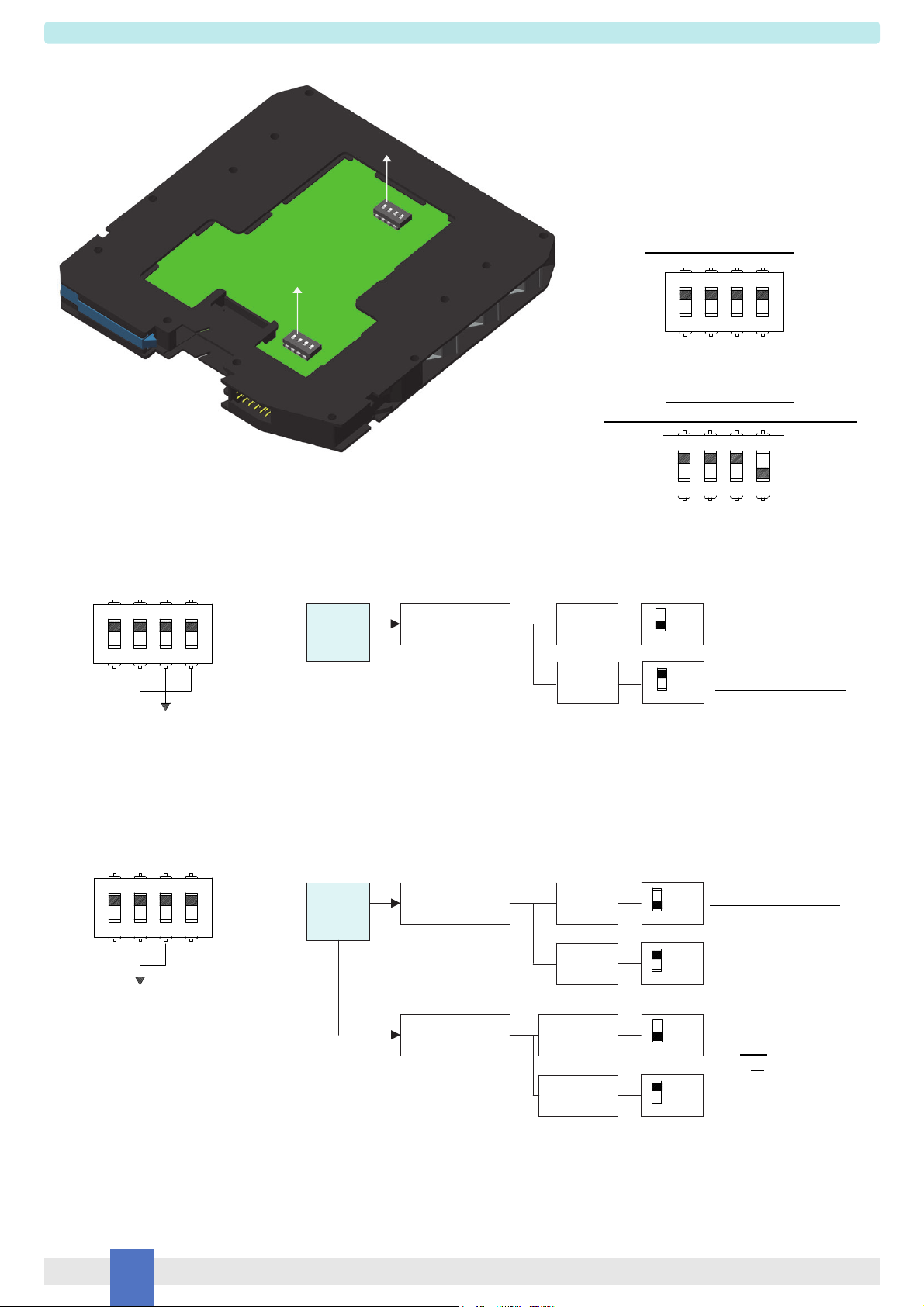
Short and open circuit diagnostic monitoring, dip-switch selectable and active when input power is present, provides LED indication and NC transistor output signaling.
When fault is detected output is de-energized until normal condition is restored. Line short and open output circuit fault detection is also reflected on the PLC / DCS input circuit
providing less than 10 mA consumption. In alternative, input impedance can be set to a value always lower than 2 k.
An override input, dip-switch selectable, is provided to permit a safety system to override the control signal. When enabled, a low input voltage always de-energizes the field device
regardless of the input signal.
Three basic output circuits are selectable, with different parameters, to interface the majority of devices on the market.
The selection among the three output characteristics is obtained by connecting the field device to a different terminal block.
Mounting on standard DIN-Rail, with or without Power Bus to provide fault signal, or on customized Termination Boards.
Functional Safety Management certification:
G.M. International is certified by TÜV to conform to IEC61508:2010 part 1 clauses 5-6 for safety related systems up to and included SIL3.
Technical Data
Characteristics
Loop Input: loop powered control signal.
Loop Supply: 24 Vdc nom (20 to 30 Vdc) reverse polarity protected, 2 A time lag fuse internally protected. Supplies also diagnostic monitoring control circuit.
Current consumption @ 24 V: 65 mA with 45 mA output typical in normal operation, 10 mA when fault circuit enabled and fault condition detected.
Power dissipation: 1.1 W with 24 V supply, output energized at 45 mA nominal load.
Override Input: override control signal de-energizes output when enabled by dip-switch.
Override range: 24 Vdc nom (20 to 30 Vdc) to disable (field device controlled by input), 0 to 5 Vdc to de-energize field device, reverse polarity protected.
Current consumption @ 24 V: 15 mA max.
Isolation (Test Voltage): Out/In 2.5 KV; Out/Fault 2.5 KV; Out/Override 2.5 KV; In/Fault 500 V; In/Override 500 V; Fault/Override 500 V.
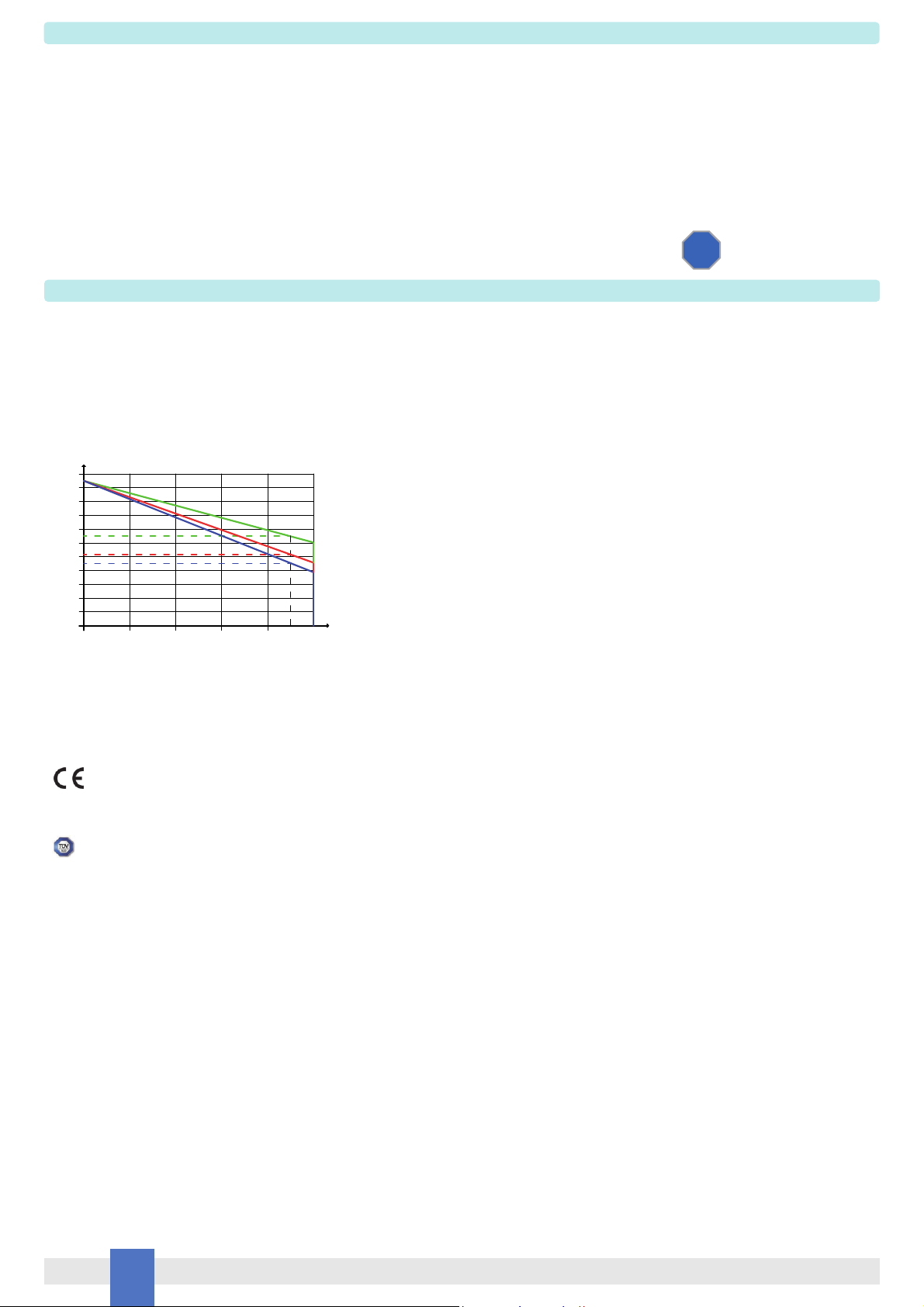
Output: 45 mA at 13.0 V (21.0 V no load, 174 series resistance) at terminals 7-10 Out A.
45 mA at 10.2 V (21.0 V no load, 236 series resistance) at terminals 8-10 Out B.
45 mA at 8.5 V (21.0 V no load, 275 series resistance) at terminals 9-10 Out C.
Short circuit current: 50 mA (55 mA typical).
Response time: 75 ms.
Fault detection: field device and wiring open circuit or short circuit detection dip-switch selectable. When fault is detected output is de-energized until normal condition is restored.
Short output detection: load resistance 50 (2 mA forcing to detect fault).
Open output detection: load resistance > 10 K.
Fault signaling: voltage free NE SPST optocoupled open-collector transistor (output de-energized in fault condition and when input power not present).
Open-collector rating: 100 mA at 35 Vdc (1.5 V voltage drop).
Leakage current: 50 µA at 35 Vdc.
Input impedance: Iin < 10 mA when fault detected or Rin < 2 k(dip-switch selectable).
Response time: 75 ms.
Compatibility:
CE mark compliant, conforms to Directive: 2014/30/EU EMC, 2014/35/EU LVD, 2011/65/EU RoHS.
Environmental conditions:
Operating: temperature limits – 40 to + 70 °C, relative humidity 95 %, up to 55 °C.
Storage: temperature limits – 45 to + 80 °C.
Approvals:
TÜV Certificate No. C-IS-722134640-01, SIL 3 conforms to IEC61508:2010 Ed.2.
TÜV Certificate No. C-IS-236198-09, SIL 3 Functional Safety Certificate conforms to IEC61508:2010 Ed.2, for Management of Functional Safety.
Mounting:
T35 DIN-Rail according to EN50022, with or without Power Bus or on customized Termination Board.
Weight: about 130 g.
Connection: by polarized plug-in disconnect screw terminal blocks to accomodate terminations up to 2.5 mm2.
Protection class: IP 20.
Dimensions: Width 12.5 mm, Depth 123 mm, Height 120 mm.
FSM
SIL 3
2
4
6
8
10
12
14
16
18
20
22
13
V (V)
I (mA)
0
D5048 Output Diagram
Rout 174 (Out A)
100 20304050
21
10.2
8.5
45
Vo 21.0 V (no load)
Rout 236 (Out B)
Rout 275 (Out C)
Ilim 50 mA
Out A
Out B
Out C
D6048 Output Diagram