GMI SIL 2 User manual

D5072-099 - SIL 2 Temperature Signal Converter G.M. International ISM0389-0
SIL 2 Temperature Signal Converter
Multifunction, DIN-Rail and Termination Board
Models D5072S-099, D5072D-099
D5072S-099 - D5072D-099
INSTRUCTION MANUAL

2 D5072-099 - SIL 2 Temperature Signal Converter G.M. International ISM0389-0
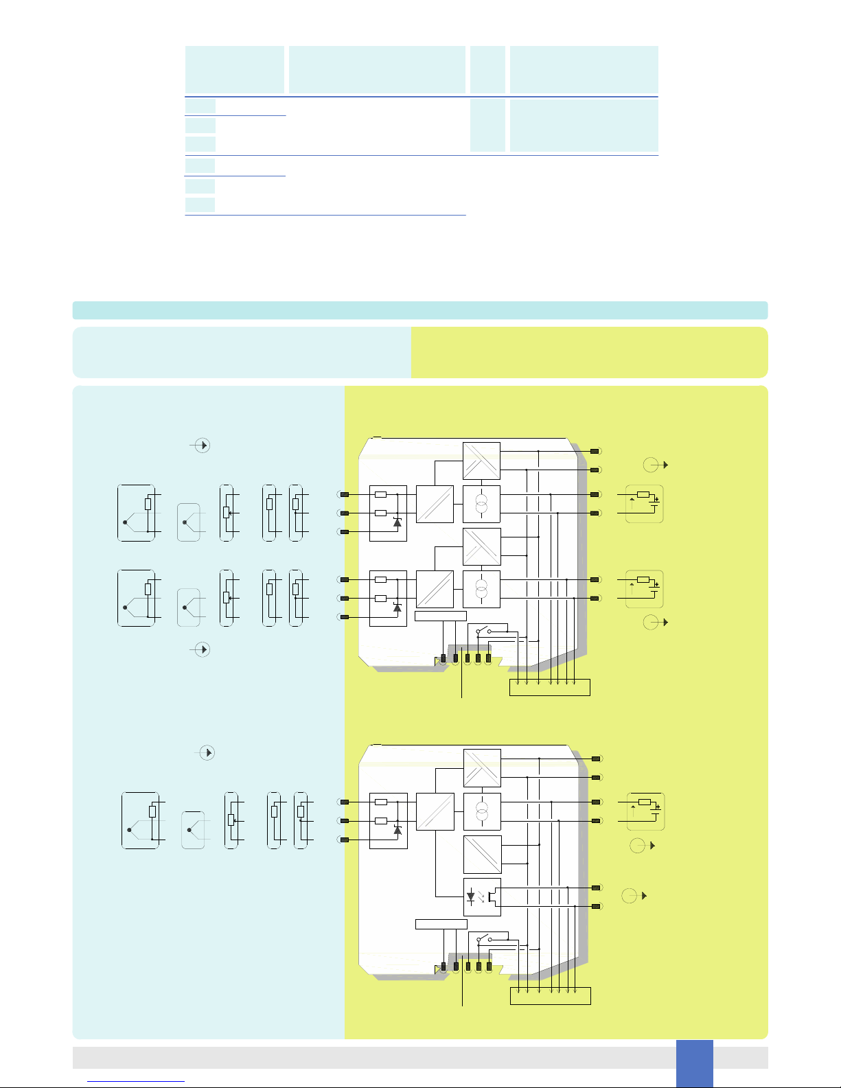
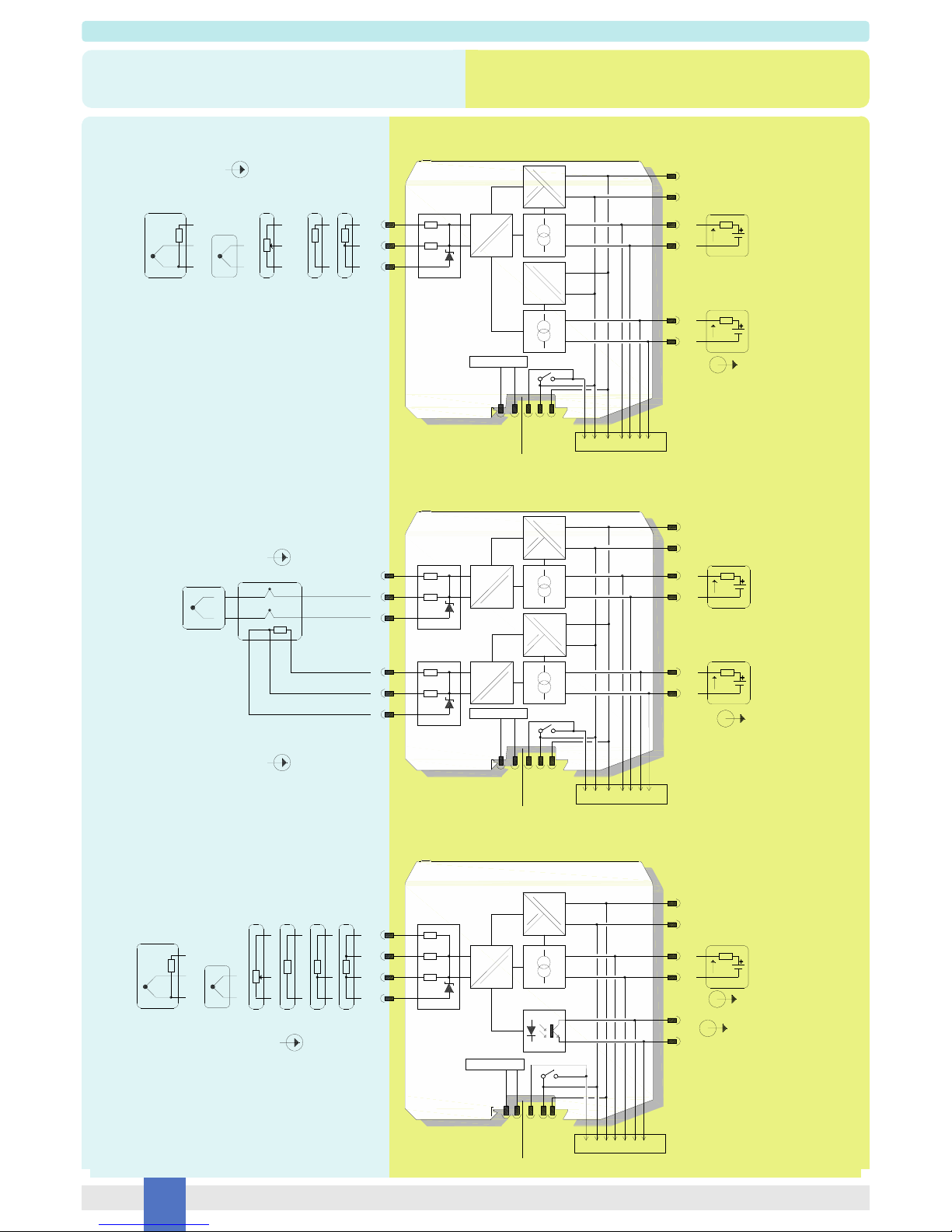
General Description: The single and dual channel Temperature Signal Converter D5072S-099 and D5072D-099 accepts a low level dc signal from millivolt, thermocouple or resistance/
RTD or transmitting potentiometer sensor, located in Hazardous Area, and converts, with isolation, the signal to drive a Safe Area load, suitable for applications requiring SIL 2 level
(according to IEC 61508:2010 ed.2) in safety related systems for high risk industries. Output signal can be direct or reverse. Modbus RTU RS-485 output is available on Bus connector.
Cold junction compensation can be programmed as:
- Automatic: provided by an internal temperature sensor;
- Fixed: to a user-customizable temperature value;
- External: making use of an external RTD;
- Remote: (only D5072D) connecting compensation RTD to one of the two channels.
For D5072D-099 module: duplicator function provides two independent outputs from one single input. Output function can be configured as: average, subtractor, low/high or redundan-
cy selector. Modules are provided with alarm function, which is available via solid state contact output, Termination Board and Power Bus. Mounting on standard DIN-Rail, with or
without Power Bus, or on customized Termination Boards, in Safe Area / Non Hazardous Location or in Zone 2 / Class I, Division 2 or Class I, Zone 2.
Technical Data
Characteristics
Supply: 24 Vdc nom (18 to 30 Vdc) reverse polarity protected, ripple within voltage limits 5 Vpp, 2 A time lag fuse internally protected.
Current cons. @ 24 V: 50 mA (D5072D-099), 35 mA (D5072S-099) with 20 mA out typical.
Power dissip. @ 24 V: 1.0 W (D5072D-099), 0.75 W (D5072S-099) with 20 mA out typical.
Isolation (Test Voltage): I.S. In/Out 2.5 KV; I.S. In/Supply 2.5 KV; I.S. In/I.S. In 500 V; Out/Supply 500 V; Out/Out 500 V.
Input: See section “Input specifications” for more details on Input sensors.
4-wire RTD input only on D5072S-099. Possibility of configuring user customized sensor (TC or RTD). Choice between °C/°F.
Integration time: from 50 ms to 500 ms depending on sensor and fast/slow integration.
Resolution: 1 µV on mV/TC, 1 mon RTD/resistance, 0.0001 % on transmitting pot.
Visualization: 0.1 °C on temp.,10 µV on mV, 10 mon resistance, 0.1 % on pot.
Input range: within sensor limits (-500 to +500 mV for mV, 0-4 kfor resistance).
Measuring RTD current: 0.15 mA.
2 wire RTD line resistance compensation: 50 (programmable).
Thermocouple Reference Junction Compensation: programmable as automatic with internal compensator, fixed (–60 to +100 °C), external with any supported RTD, or remote
using 1 channel (D5072D-099).
Thermocouple burnout current: 50 µA.
Fault: enabled or disabled. Analog output can be programmed to reflect fault conditions via downscale, highscale or customized value forcing. Fault conditions are also signaled via BUS
and by red LED on front panel for each channel. Fault conditions are: Sensor burnout, Sensor out of range, Output saturation, Internal fault, Cable resistance fault.
Output: Fully customizable 0/4 to 20 mA, on max. 300 load source mode, current limited at 24 mA. In sink mode, external voltage generator range is V min. 3.5V at 0load and V
max. 30V. If generator voltage Vg > 10 V, a series resistance (Vg - 10)/0.024 is needed. The maximum value of series resistance is (Vg - 3.5)/0.024 .
Resolution: 1 µA current output.
Transfer characteristic: linear, direct or reverse on all input sensors.
Response time: 20 ms (10 to 90 % step).
Output ripple: 20 mVrms on 250 load.
Damping factor: 30 s, configurable.
Modbus Output: Modbus RTU protocol, from 4800 to 115.200 bps.
Alarm: Trip point range: within rated limits of input sensor (see input step resolution).
ON-OFF delay time: 0 to 1000 s, 100 ms step.
Hysteresis: within rated limits of input sensor.
Output: voltage free SPST photoMOS: 100 mA, 60 Vdc (1 V voltage drop).
Performance: Ref. Conditions 24 V supply, 250 load, 23 ± 1 °C ambient temperature, slow integration mode, 4-wires (for D5072S-099) or 3-wires (for D5072D-099) configuration for
RTD.
Input: Calibration and linearity accuracy: see section “Input Specifications”.
Temperature influence: see section “Input Specifications”.
Ref. Junction Compensation influence: ± 1 °C (internal PT1000 sensor).
Analog Output: Calibration accuracy: ±0.05 % of full scale.
Linearity error: ±0.05 % of full scale.
Supply voltage influence: ±0.02 % of full scale for a min to max supply change.
Load influence: ±0.02 % of full scale for a 0 to 100 % load resistance change.
Temperature influence: ±1µA for a 1 °C change.
Compatibility:
CE mark compliant, conforms to Directive:
2014/34/EU ATEX, 2014/30/EU EMC, 2014/35/EU LVD, 2011/65/EU RoHS.
Environmental conditions:
Operating: temperature limits – 40 to + 70 °C, relative humidity 95 %, up to 55 °C.
Storage: temperature limits – 45 to + 80 °C.
Safety Description:
ATEX: II 3(1)G Ex nA [ia Ga] IIC T4 Gc, II (1)D [Ex ia Da] IIIC, I (M1) [Ex ia Ma] I
IECEx / INMETRO / NEPSI: Ex nA [ia Ga] IIC T4 Gc, [Ex ia Da] IIIC, [Ex ia Ma] I,
EAC-EX: 2Ex nA [ia Ga] IIC T4 Gc X, [Ex ia Da] IIIC, [Ex ia Ma] I.
UKR TR n. 898: 2ExnAiaIICT4 X, ExiaI X
associated apparatus and non-sparking electrical equipment.
D5072S-099: Uo/Voc = 7.2 V, Io/Isc = 23 mA, Po/Po = 40 mW,
Ui/Vmax = 12.8 V, Ci = 0 nF, Li = 0 nH at terminals 7-8-9-10.
D5072D-099: Uo/Voc = 7.2 V, Io/Isc = 16 mA, Po/Po = 27 mW,
Ui/Vmax = 12.8 V, Ci = 0 nF, Li = 0 nH at terminals 7-8-9, 10-11-12.
Um = 250 Vrms or Vdc, -40 °C Ta 70 °C.
Approvals:
BVS 12 ATEX E 053 X conforms to EN60079-0, EN60079-11, EN60079-15.
IECEx BVS 12.0050X conforms to IEC60079-0, IEC60079-11, IEC60079-15.
INMETRO DNV 13.0110 X conforms to ABNT NBR IEC60079-0, ABNT NBR IEC60079-11, ABNT NBR IEC60079-15, ABNT NBR IEC60079-26.
C-IT.MH62.B.04182 conforms to GOST R IEC 60079-0,GOST R IEC 60079-11, GOST R IEC 60079-15.
C16.0036 X conforms to 7113, 22782.5-78, I 60079-15.
GYJ14.1406X conforms to GB3836.1, GB3836.4; GB3836.8, GB3836.20.
SIL 2 according to IEC 61508:2010 ed.2 (pending).
Mounting:
EN/IEC60715 TH 35 DIN-Rail, with or without Power Bus or on customized Termination Board.
Weight: about 135 g D5072D-099, 130 g D5072S-099.
Connection: by polarized plug-in disconnect screw terminal blocks to accommodate terminations up to 2.5 mm2.
Location: installation in Safe Area/Non Hazardous Locations or Zone 2, Group IIC T4 or Class I, Division 2, Group A,B,C,D, T4 or Class I, Zone 2, Group IIC, T4.
Protection class: IP 20.
Dimensions: Width 12.5 mm, Depth 123 mm, Height 120 mm.
The module is fully programmable. Operating parameters can be changed from PC via PPC5092 adapter connected to USB serial line and SWC5090 software.
Measured values and diagnostic alarms can be read on both serial configuration or Modbus output line.
SWC5090 software also allows the Monitoring and Recording of values. For details please see SWC5090 manual ISM0154.
Programming

3
D5072-099 - SIL 2 Temperature Signal ConverterG.M. International ISM0389-0
Ordering Information
Front Panel and Features
SIL 2 according to IEC61508:2010 ed.2 for Tproof=3/10yrs (10% / >10 % of total SIF) with analog current output.
Input from Zone 0 (Zone 20) / Division 1, installation in Zone 2 / Division 2.
mV, thermocouple, 2 or 3 or 4 wire resistance/RTD or transmitting potentiometer Input Signal.
2-wire RTD line resistance compensation.
Internal Reference Junction Compensation.
Fastest integration time: 50 ms
Fully customizable Output range from 0 to 24 mA Output Signal linear or reverse (typical 0/4-20 mA).
Output duplication possible for D5072D-099.
Modbus RTU RS-485 Output.
Independent multiple Fault detection.
Programmable alarm available on solid state contact output or Termination Board connector.
High Accuracy, µP controlled A/D converter.
Three port isolation, Input/Output/Supply.
EMC Compatibility to EN61000-6-2, EN61000-6-4, EN61326-1, EN61326-3-1 for safety system.
Fully programmable operating parameters.
ATEX, IECEx, INMETRO, EAC-EX, UKR TR n. 898, NEPSI Certifications.
TÜV Certification (pending).
High Density, two channels per unit.
Simplified installation using standard DIN-Rail and plug-in terminal blocks, with or without Power Bus, or customized
Termination Boards.
250 Vrms or Vdc (Um) max. voltage allowed to the instruments associated with the barrier.
Data logging and monitoring via software.
D5072S-099: +Input for thermocouple TC or for 3, 4 wire RTD or potentiometer
D5072D-099: +Input Ch1 for thermocouple TC or for 3 wire RTD or potentiometer
Terminal block connections
HAZARDOUS AREA SAFE AREA
D5072S-099: -Input for thermocouple TC or for 2, 3, 4 wire RTD or potentiometer
D5072D-099: -Input Ch1 for thermocouple TC or for 2, 3 wire RTD or potentiometer
D5072S-099: Input for 2, 3, 4 wire RTD or potentiometer
D5072D-099: Input Ch1 for 2, 3 wire RTD or potentiometer
D5072S-099: Input for 4 wire RTD
D5072D-099: Input Ch2 for 2, 3 wire RTD or potentiometer
D5072D-099: +Input Ch2 for thermocouple TC or for 3 wire RTD
or potentiometer
D5072D-099: -Input Ch2 for thermocouple TC or for 2, 3 wire RTD
or potentiometer
7
8
9
10
11
12
+Output Ch1 (sink current mode)
1
-Output Ch1 (sink current mode)
2
D5072S-099 (Alarm), D5072D-099 (Current/Alarm):
+Output Ch2 (sink current) or +Output (Alarm/Fault)
3
D5072S-099 (Alarm), D5072D-099 (Current/Alarm):
-Output Ch2 (sink current) or -Output (Alarm/Fault)
4
+Power Supply 24 Vdc
5
-Power Supply 24 Vdc
6
7 8
9 10
11 12
12
34
56
SIL 2
5 6
2
4
1
3
7 8
12
10
11
9
D5072
-099
CONFIG
PWR
FLT 1
FLT 2
/ ALR
Power Bus and DIN-Rail accessories:
Connector JDFT049 Cover and fix MCHP196
Terminal block male MOR017 Terminal block female MOR022
Model: D5072
1 channel S
2 channels D
-099

4 D5072-099 - SIL 2 Temperature Signal Converter G.M. International ISM0389-0
Parameters Table
Must
be
Hazardous Area/
Hazardous Locations
Device Parameters
D5072-099 Associated
Apparatus Parameters
Must
be
Hazardous Area/
Hazardous Locations
Device + Cable Parameters
Uo / Voc = 7.2 V Ui / Vmax
In the system safety analysis, always check the Hazardous Area/Hazardous Locations devices to conform with the related system documentation, if the device is Intrinsically Safe check
its suitability for the Hazardous Area/Hazardous Locations and group encountered and that its maximum allowable voltage, current, power (Ui/Vmax, Ii/Imax, Pi/Pi) are not exceeded
by the safety parameters (Uo/Voc, Io/Isc, Po/Po) of the D5072 series Associated Apparatus connected to it. Also consider the maximum operating temperature of the field device,
check that added connecting cable and field device capacitance and inductance do not exceed the limits (Co/Ca, Lo/La, Lo/Ro) given in the Associated Apparatus parameters for the
effective group. See parameters indicated in the table below:
D5072-099
Terminals
Ch1 7 - 8 - 9 - 10
D5072S-099
Ch1
Ch2
7 - 8 - 9
10 - 11 - 12
Io / Isc = 23 mA
Io / Isc = 16 mA
Po / Po = 40 mW
Po / Po = 27 mW
Ii/ Imax
Pi / Pi
D5072-099
Terminals
Ch1
Ch2
7 - 8 - 9
10 - 11 - 12
D5072-099 Associated Apparatus
Parameters Cenelec (US)
Ci / Ci device + C cable
IIC (A, B)
Co / Ca = 13.5 µF
Co / Ca = 240 µF
Co / Ca = 1000 µF
IIB (C)
IIA (D)
IIC (A, B)
Co / Ca = 13.5 µF
Co / Ca = 240 µF
Co / Ca = 1000 µF
IIB (C)
IIA (D)
Co / Ca = 1000 µF
Co / Ca = 240 µF
I
IIIC (E, F, G)
I
Co / Ca = 1000 µF
Co / Ca = 240 µF
Ch1 7 - 8 - 9 - 10
Li / Li device + L cable
IIC (A, B)
Lo / La = 67 mH
Lo / La = 268 mH
Lo / La = 537 mH
IIB (C)
IIA (D)
IIC (A, B)
Lo / La = 138 mH
Lo / La = 555 mH
Lo / La = 1111 mH
IIB (C)
IIA (D)
Lo / La = 882 mH
Lo / La = 268 mH
I
IIIC (E, F, G)
I
Lo / La = 1822 mH
Lo / La = 555 mH
Li / Ri device and
L cable / R cable
IIC (A, B)
Lo / Ro = 875 µH/
Lo / Ro = 3500 µH/
Lo / Ro = 7000 µH/
IIB (C)
IIA (D)
IIC (A, B)
Lo / Ro = 1290 µH/
Lo / Ro = 5160 µH/IIB (C)
IIA (D)
Lo / Ro = 11480 µH/
Lo / Ro = 3500 µH/
I
IIIC (E, F, G)
I
IIIC (E, F, G)
Lo / Ro = 16950 µH/
Lo / Ro = 5160 µH/
Lo / Ro = 10330 µH/
IIIC (E, F, G)
IIIC (E, F, G)
D5072D-099
Ch1 7 - 8 - 9 - 10
D5072S-099
Ch1
Ch2
7 - 8 - 9
10 - 11 - 12
D5072D-099
Ch1 7 - 8 - 9 - 10
D5072S-099
Ch1
Ch2
7 - 8 - 9
10 - 11 - 12
D5072D-099
D5072S-099
D5072D-099
Ch1
Ch2
7 - 8 - 9
10 - 11 - 12
Ch1 7 - 8 - 9 - 10
D5072S-099
D5072D-099
Ch1
Ch2
7 - 8 - 9
10 - 11 - 12
Ch1 7 - 8 - 9 - 10D5072S-099
D5072D-099

5
D5072-099 - SIL 2 Temperature Signal ConverterG.M. International ISM0389-0
When used with separately powered intrinsically safe devices, check that maximum allowable voltage, current (Ui/Vmax, Ii/Imax) of the D5072-099 Associated Apparatus are not exceed-
ed by the safety parameters (Uo/Voc, Io/Isc) of the Intrinsically Safe device, indicated in the table below:
For installations in which both the Ci and Li of the Intrinsically Safe apparatus exceed 1 % of the Co and Lo parameters of the Associated Apparatus (excluding the cable),
then 50 % of Co and Lo parameters are applicable and shall not be exceeded (50 % of the Co and Lo become the limits which must include the cable such that Ci device + C cable
50 % of Co and Li device + L cable 50 % of Lo). The reduced capacitance of the external circuit (including cable) shall not be greater than 1 F for Groups I, IIA, IIB and 600 nF for
Group IIC.
If the cable parameters are unknown, the following value may be used: Capacitance 200 pF per meter (60 pF per foot), Inductance 1 µH per meter (0.20 µH per foot).
Must
be
Hazardous Area/
Hazardous Locations
Device Parameters
D5072-099 Associated
Apparatus Parameters
Ui / Vmax = 12.8 V Uo / Voc
D5072-099
Terminals
Ci = 0 nF, Li= 0 nH
Function Diagram
HAZARDOUS AREA ZONE 0 (ZONE 20) GROUP IIC,
HAZARDOUS LOCATIONS CLASS I, DIVISION 1, GROUPS A, B, C, D,
CLASS II, DIVISION 1, GROUPS E, F, G, CLASS III, DIVISION 1,
CLASS I, ZONE 0, GROUP IIC
SAFE AREA, ZONE 2 GROUP IIC T4,
NON HAZARDOUS LOCATIONS, CLASS I, DIVISION 2,
GROUPS A, B, C, D T-Code T4, CLASS I, ZONE 2, GROUP IIC T4
Ch1 7 - 8 - 9 - 10
D5072S-099
Ch1
Ch2
7 - 8 - 9
10 - 11 - 12
D5072D-099
Ch1 7 - 8 - 9 - 10
D5072S-099
Ch1
Ch2
7 - 8 - 9
10 - 11 - 12
D5072D-099
==
=
5 +
6 -
1
2
3
4
9
7
12
10
MODEL D5072D-099
=
=
=
=
Out 1 (SIL 2)
11
8
+
-Termination
board
connector
F
Power and
Fault Bus
Supply 24 Vdc
Modbus RS485
A-B+
Modbus RS485 Out 2 (SIL 2)
==
=
In 1
In 2
+
-
TC / mV
2-3 wires
RTD / Resistance
Pot.
2-3 wires
RTD / ResistancePot.
TC +
ext. comp.
+
-
TC / mV
TC +
ext. comp.
mA
Sink I
-
+
RL
mA
Sink I
-
+
RL
==
=
5 +
6 -
1
2
3 +
4 -
9
7
MODEL D5072D-099 (Alarm / Fault)
=
=
Out 1-A (SIL 2)
8
+
-Termination
board
connector
F
Power and
Fault Bus
Supply 24 Vdc
Modbus RS485
A-B+
Modbus RS485
=
=
Alarm / Fault
Out 1-B (SIL 2)
In 1
+
-
TC / mV
2-3 wires
RTD / Resistance
Pot.
TC +
ext. comp.
mA
Sink I
-
+
RL

6 D5072-099 - SIL 2 Temperature Signal Converter G.M. International ISM0389-0
Function Diagram
HAZARDOUS AREA ZONE 0 (ZONE 20) GROUP IIC,
HAZARDOUS LOCATIONS CLASS I, DIVISION 1, GROUPS A, B, C, D,
CLASS II, DIVISION 1, GROUPS E, F, G, CLASS III, DIVISION 1,
CLASS I, ZONE 0, GROUP IIC
SAFE AREA, ZONE 2 GROUP IIC T4,
NON HAZARDOUS LOCATIONS, CLASS I, DIVISION 2,
GROUPS A, B, C, D T-Code T4, CLASS I, ZONE 2, GROUP IIC T4
==
=
5 +
6 -
1
2
3
4
9
7
MODEL D5072D-099 (Duplicator)
=
=
8
+
-Termination
board
connector
F
Power and
Fault Bus
Supply 24 Vdc
Modbus RS485
A-B+
Modbus RS485 Out 1-B (SIL 2)
=
=
In 1
+
-
TC / mV
2-3 wires
RTD / Resistance
Pot.
TC +
ext. comp.
mA
Sink I
-
+
RL
mA
Sink I
-
+
RL
==
=
5 +
6 -
1
2
3
4
9
7
12
10
=
=
=
=
11
8
+
-Termination
board
connector
F
Power and
Fault Bus
Supply 24 Vdc
Modbus RS485
A-B+
Modbus RS485 Out 2 (SIL 2)
==
=
In 1
RTD for
Cold Junction Compensation
+
-
TC
Copper wire
Copper wire
In 2
MODEL D5072D-099 (with optional remote CJC)
mA
Sink I
-
+
RL
mA
Sink I
-
+
RL
==
=
5 +
6 -
1
2
9
10
MODEL D5072S-099
=
=
7
8
+
-Termination
board
connector
F
Power and
Fault Bus
Supply 24 Vdc
3 +
4 -
Modbus RS485
A-
B+
Out 1-A (SIL 2)
mA
Sink I
-
+
RL
Alarm / Fault Out 1-B
In
2-3-4 wires
RTD / Resistance
Pot.
Modbus RS485
+
-
TC / mV
TC +
ext. comp.

7
D5072-099 - SIL 2 Temperature Signal ConverterG.M. International ISM0389-0
D5072-099 series are isolated Intrinsically Safe Associated Apparatus installed into standard EN/IEC60715 TH 35 DIN-Rail located in Safe Area or Zone 2, Group IIC, Temperature T4
Hazardous Area (according to EN/IEC60079-15) within the specified operating temperature limits Tamb -40 to +70 °C, and connected to equipment with a maximum limit for AC power
supply Um of 250 Vrms or Vdc.
Not to be connected to control equipment that uses or generates more than 250 Vrms or Vdc with respect to earth ground.
D5072-099 series must be installed, operated and maintained only by qualified personnel, in accordance to the relevant national/international installation standards (e.g. EN/
IEC60079-14 Electrical apparatus for explosive gas atmospheres - Part 14: Electrical installations in hazardous areas (other than mines)), following the established installation rules,
particular care shall be given to segregation and clear identification of I.S. conductors from non I.S. ones.
De-energize power source (turn off power supply voltage) before plug or unplug the terminal blocks when installed in Hazardous Area or unless area is known to be nonhazardous.
Warning: substitution of components may impair Intrinsic Safety and suitability for Zone 2.
Explosion Hazard: to prevent ignition of flammable or combustible atmospheres, disconnect power before servicing or unless area is known to be nonhazardous.
Failure to properly installation or use of the equipment may risk to damage the unit or severe personal injury.
The unit cannot be repaired by the end user and must be returned to the manufacturer or his authorized representative. Any unauthorized modification must be avoided.
Warning
Operation
Each input channel of Temperature Signal Converter D5072-099 accepts a low level dc signal from millivolt, thermocouple or 2-3-4 wire RTD temperature or transmitting potentiometer
sensor, located in Hazardous Area, and converts, with isolation, the signal to a 4-20 mA floating output current to drive a Safe Area load.
Presence of supply power is displayed by a “POWER ON” green signaling LED; integrity of field sensor and connecting line can be monitored by a configurable burnout circuit which, if
enabled, can drive output signal to upscale or downscale limit. Burnout condition is signaled by red front panel LED for each channel.
D5072D-099 module has double input and output channel, and can also be programmed to interface a single input and obtain dual output channel (duplicator) or configurable output
channel (outputs can repeat the corresponding inputs or be proportional to the sum or difference of the two input process variables or with low/high selector function).
Installation
D5072-099 series are Temperature Signal Converter housed in a plastic enclosure suitable for installation on EN/IEC60715 TH 35 DIN-Rail, with or without Power Bus or on customized
Termination Board.
D5072-099 unit can be mounted with any orientation over the entire ambient temperature range.
Electrical connection of conductors up to 2.5 mm² are accommodated by polarized plug-in removable screw terminal blocks which can be plugged in/out into a powered unit without
suffering or causing any damage (for Zone 2 installations check the area to be nonhazardous before servicing). Connect only one individual conductor per each clamping point, use
conductors up to 2.5 mm2 and a torque value of 0.5-0.6 Nm. Use only cables that are suitable for a temperature of at least 85°C.
The wiring cables have to be proportionate in base to the current and the length of the cable.
On the section “Function Diagram” and enclosure side a block diagram identifies all connections.
Intrinsically Safe conductors must be identified and segregated from non I.S. and wired in accordance to the relevant national/international installation standards (e.g. EN/IEC60079-14
Electrical apparatus for explosive gas atmospheres - Part 14: Electrical installations in hazardous areas (other than mines)), make sure that conductors are well isolated from each other
and do not produce any unintentional connection.
Connect alarm transistors checking the load rating to be within the maximum rating (100 mA at 60 Vdc (1 V voltage drop)).
The enclosure provides, according to EN60529, an IP20 minimum degree of protection (or similar to NEMA Standard 250 type 1). The unit shall be installed in an area of not more than
pollution degree 2 according to EN/IEC60664-1. For hazardous location, the unit shall be installed in a certified Ex enclosure with a minimum ingress protection of at least IP54 in
accordance with EN/IEC60079-15, that must have a door or cover accessible only by the use of a tool.
Units must be protected against dirt, dust, extreme mechanical (e.g. vibration, impact and shock) and thermal stress, and casual contacts. If enclosure needs to be cleaned use only a
cloth lightly moistened by a mixture of detergent in water.
Electrostatic Hazard: to avoid electrostatic hazard, the enclosure of D5072-099 must be cleaned only with a damp or antistatic cloth.
Any penetration of cleaning liquid must be avoided to prevent damage to the unit. Any unauthorized modification must be avoided.
According to EN61010, D5072-099 series must be connected to SELV or SELV-E supplies.
All circuits connected to D5072-099 unit must comply with the overvoltage category II (or better) according to EN/IEC60664-1.
Start-up
Before powering the unit check that all wires are properly connected, particularly supply conductors and their polarity, input and output wires, also check that Intrinsically Safe conductors
and cable trays are segregated (no direct contacts with other non I.S. conductors) and identified either by color coding, preferably blue, or by marking.
Check conductors for exposed wires that could touch each other causing dangerous unwanted shorts.
Check that the module has been correctly configured through SWC5090 software. For details please see SWC5090 manual ISM0154
Turn on power, the “power on” green LED must be lit, output on each channel must be in accordance with the corresponding input signal value and input/output chosen transfer function.
If possible change the sensor condition and check the corresponding Safe Area output.

8 D5072-099 - SIL 2 Temperature Signal Converter G.M. International ISM0389-0
Input specifications
Input specifications:
Notes:
RTD/resistance accuracy shown in 4-wires (for D5072S-099) or 3-wires (for D5072D-099) configuration, in slow acquisition mode.
TC/mV Accuracy shown in slow acquisition mode.
Input Type Alpha
[°C-1]Nominal
resistance [Ω]Standards Min Span
[°C (°F)] Accuracy
[°C (°F)] Accuracy Range
[°C (°F)] Maximum Range
[°C (°F)] Temperature Influence
per °C typical [°C (°F)]
RTD
Platinum
0.003851
50
IEC 60751
GOST 6651
JIS C 1604
40 (72) ±0.5 (±0.9)
-200 to 850
(-328 to 1562) -200 to 850
(-328 to 1562) ±0.015
(±0.027)
100 20 (36) ±0.2 (±0.4)
200
10 (18) ±0.1 (±0.2)
300
400
500
1000
0.003916 100 JIS C 1604 20 (36) ±0.2 (±0.4) -200 to 630
(-328 to 1166) -200 to 630
(-328 to 1166) ±0.015
(±0.027)
0.003926 100 --- 20 (36) ±0.2 (±0.4) -200 to 630
(-328 to 1166) -200 to 630
(-328 to 1166) ±0.015
(±0.027)
0.003911
46
GOST 6651
40 (72) ±0.5 (±0.9)
-200 to 650
(-328 to 1202) -200 to 650
(-328 to 1202) ±0.015
(±0.027)
50
100 20 (36) ±0.2 (±0.4)
200
±0.1 (±0.2)
300
400
500
Nickel
0.006178 100 DIN 43760
10 (18)
±0.2 (±0.4) -60 to 180
(-76 to 356) -60 to 180
(-76 to 356) ±0.015
(±0.027)
0.006720 120 --- ±0.2 (±0.4)
-80 to 260
(-112 to 500) -80 to 260
(-112 to 500) ±0.015
(±0.027)
Copper
0.004260 53 GOST 6651 20 (36) ±0.3 (±0.5) -50 to 180
(-58 to 356) -50 to 180
(-58 to 356) ±0.015
(±0.027)
0.004280 50 GOST 6651 20 (36) ±0.3 (±0.5) -50 to 200
(-58 to 392) -50 to 200
(-58 to 392) ±0.015
(±0.027)
100 10 (18) ±0.2 (±0.4)
0.004274 9.035 --- 100 (180) ±1.7 (±3.1) -200 to 260
(-328 to 500) -200 to 260
(-328 to 500) ±0.050
(±0.090)
TC
A1 --- GOST 8.585 150 (270) ±0.7 (±1.3) 0 to 2500
(32 to 4532) 0 to 2500
(32 to 4532) ±0.090
(±0.162)
A2 --- GOST 8.585 100 (180) ±0.5 (±0.9) 0 to 1800
(32 to 3272) 0 to 1800
(32 to 3272) ±0.050
(±0.090)
A3 --- GOST 8.585 100 (180) ±0.5 (±0.9) 0 to 1800
(32 to 3272) 0 to 1800
(32 to 3272) ±0.050
(±0.090)
B ---
IEC 60584
GOST 8.585
ASTM E230 200 (360) ±1.1 (±2.0) 450 to 1820
(842 to 3308) 0 to 1820
(32 to 3308) ±0.060
(±0.108)
C ---
ASTM E230
ASTM E988 100 (180) ±0.6 (±1.1) 0 to 2315
(32 to 4199) 0 to 2315
(32 to 4199) ±0.080
(±0.144)
D --- ASTM E988 100 (180) ±0.6 (±1.1) 0 to 2315
(32 to 4199) 0 to 2315
(32 to 4199) ±0.080
(±0.144)
E ---
IEC 60584
GOST 8.585
ASTM E230 50 (90) ±0.2 (±0.4) -150 to 1000
(-238 to 1832) -270 to 1000
(-454 to 1832) ±0.050
(±0.090)
J ---
IEC 60584
GOST 8.585
ASTM E230 50 (90) ±0.2 (±0.4) -150 to 1200
(-238 to 2192) -210 to 1200
(-346 to 2192) ±0.050
(±0.090)
K ---
IEC 60584
GOST 8.585
ASTM E230 50 (90) ±0.3 (±0.5) -150 to 1372
(-238 to 2502) -270 to 1372
(-454 to 2502) ±0.050
(±0.090)
L (type “L” DIN) --- DIN 43710 50 (90) ±0.2 (±0.4) -200 to 900
(-328 to 1652) -200 to 900
(-328 to 1652) ±0.050
(±0.090)
LR (type “L” GOST) --- GOST 8.585 50 (90) ±0.3 (±0.5) -200 to 800
(-328 to 1472) -200 to 800
(-328 to 1472) ±0.050
(±0.090)
N ---
IEC 60584
GOST 8.585
ASTM E230 50 (90) ±0.4 (±0.7) -150 to 1300
(-238 to 2372) -270 to 1300
(-454 to 2372) ±0.060
(±0.108)
R ---
IEC 60584
GOST 8.585
ASTM E230 150 (270) ±0.8 (±1.4) 50 to 1768
(122 to 3214) -50 to 1768
(-58 to 3214) ±0.060
(±0.108)
S ---
IEC 60584
GOST 8.585
ASTM E230 150 (270) ±0.8 (±1.4) 50 to 1768
(122 to 3214) -50 to 1768
(-58 to 3214) ±0.060
(±0.108)
T ---
IEC 60584
GOST 8.585
ASTM E230 50 (90) ±0.2 (±0.4) -100 to 400
(-148 to 752) -270 to 400
(-454 to 752) ±0.020
(±0.036)
U --- DIN 43710 50 (90) ±0.4 (±0.7) -200 to 600
(-328 to 1112) -200 to 600
(-328 to 1112) ±0.040
(±0.072)
Type Nominal
resistance [Ω]Min Span
[Ω]Accuracy
[Ω]Accuracy Range
[Ω]Maximum Range
[Ω]Temperature Influence
per °C typical [Ω]
Ohm
Resistance standard 0 to 1000 5 ±0.2 0 to 1000 0 to 1000 ±0.02
Resistance extended 0 to 4000 20 ±0.4 0 to 4000 0 to 4000 ±0.20
Potentiometer 100 to 10000 1% ±0.1% 0 to 100% 0 to 100% ±0.02%
Type Min Span
[mV] Accuracy
[µV] Accuracy Range
[mV] Maximum Range
[mV] Temperature Influence
per °C typical [µV]
mV DC standard 1 ±10 -50 to 80 -100 to 100 ±3
DC extended 10 ±100 -500 to 500 -500 to 500 ±20
10 (18)

9
D5072-099 - SIL 2 Temperature Signal ConverterG.M. International ISM0389-0
Supported Modbus functions:
Code Name Notes
03 read holding registers reads a stream of words from memory
04 read input registers reads a stream of words from memory
08 diagnostics: subcode 0 returns query data
06 write single register writes a word in memory
16 write multiple registers writes a stream of words in memory
Supported Modbus parameters:
The unit can communicate via Modbus RTU RS-485 protocol. Below is a list of all
available registers.
Each Modbus parameter is described by one 16-bit word.
- 'Addr.' is the address of the parameter.
- 'Description' explains the function of the parameter.
- 'Rights' identifies the operation that can be executed by the user:
RO (Read Only);
WO (Write Only);
RW (Read and Write).
- 'Type' indicates the kind of the variable:
SINT8 / UINT8: signed / unsigned 8 bits integer;
SINT16 / UINT16: signed / unsigned 16 bits integer;
SINT32 / UINT32: signed / unsigned 32 bits integer;
FLOAT: floating point single precision real;
DOUBLE: floating point double precision real;
the suffix '[n]' indicates an array of n elements of the corresponding type.
Addr. Description Rights Type
IDENTIFICATION
0 GM International code RO UINT16
1 Software revision RO UINT16
2 Product code RO UINT16
3 Option code RO UINT16
4 Hardware revision RO UINT16
COMMAND EXECUTION
100 Command (*1) WO UINT16
GENERAL CONFIGURATION
202 Fault on bus mask (*2) RW UINT32
MODBUS COMMUNICATION
300 Modbus address RW UINT16
301 Modbus baud-rate (*3) RW UINT16
302 Modbus format (*4) RW UINT16
GENERAL DEBUG
400 Time stamp [100ms] RO UINT32
404 Cumulative faults (*2) RO UINT32
TAG
700 Tag 1 RW UINT8[16]
708 Tag 2 RW UINT8[16]
OUTPUT CONFIGURATION
800 Input to analog out 1 function (*5) RW UINT16
801 Input to analog out 2 function (*5) RW UINT16
ALARM CONFIGURATION
803 Input to alarm 2 function (*5) RW UINT16
INPUT CONFIGURATION
804 Integration speed (*6) RW UINT16
900 Ch1: sensor family (*7) RW UINT16
901 Ch1: sensor connection (*8) RW UINT16
902 Ch1: sensor type (*9) RW UINT16
903 Ch1: sensor burnout configuration (*10) RW UINT16
904 Ch1: cold junction compensation (*11) RW UINT16
905 Ch1: cold junction external type (*9) RW UINT16
1000 Ch2: sensor family (*7) RW UINT16
1001 Ch2: sensor connection (*8) RW UINT16
1002 Ch2: sensor type (*9) RW UINT16
1003 Ch2: sensor burnout configuration (*10) RW UINT16
1004 Ch2: cold junction compensation (*11) RW UINT16
1005 Ch2: cold junction external type (*9) RW UINT16
1100 Ch1: cold junction fixed value [0.1°C] RW SINT32
1102 Ch1: 2-wire rtd correction [mOhm] RW SINT32
1104 Ch1: rtd multiplier RW FLOAT
1200 Ch2: cold junction fixed value [0.1°C] RW SINT32
1202 Ch2: 2-wire rtd correction [mOhm] RW SINT32
1204 Ch2: rtd multiplier RW FLOAT
1500 Ch1: sensor value (volt, res, ratio) [uV, mOhm,
ppm] RO SINT32
MEASURE
1502 Ch1: cold junction resistance value [mOhm] RO SINT32
1504 Ch1: sensor temperature [0.1°C] RO SINT32
1506 Ch1: cold junction temperature [0.1°C] RO SINT32
1600 Ch2: sensor value (volt, res, ratio) [uV, mOhm,
ppm] RO SINT32
Addr. Description Rights Type
1602 Ch2: cold junction resistance value [mOhm] RO SINT32
1604 Ch2: sensor temperature [0.1°C] RO SINT32
1606 Ch2: cold junction temperature [0.1°C] RO SINT32
OUTPUT CONFIGURATION
1900 Ch1: output downscale [100nA] RW SINT32
1902 Ch1: output upscale [100nA] RW SINT32
1904 Ch1: output underrange [100nA] RW SINT32
1906 Ch1: output overrange [100nA] RW SINT32
1908 Ch1: output in case of fault [100nA] RW SINT32
1910 Ch1: output fault mask (*2) RW UINT32
1916 Ch1: output damping factor [s] RW UINT32
1918 Ch1: input downscale [uV, mOhm, ppm] RW SINT32
1920 Ch1: input upscale [uV, mOhm, ppm] RW SINT32
2000 Ch2: output downscale [100nA] RW SINT32
2002 Ch2: output upscale [100nA] RW SINT32
2004 Ch2: output underrange [100nA] RW SINT32
2006 Ch2: output overrange [100nA] RW SINT32
2008 Ch2: output in case of fault [100nA] RW SINT32
2010 Ch2: output fault mask (*2) RW UINT32
2016 Ch2: output damping factor [s] RW UINT32
2018 Ch2: input downscale [uV, mOhm, ppm] RW SINT32
2020 Ch2: input upscale [uV, mOhm, ppm] RW SINT32
OUTPUT DEBUG
2302 Ch1: output virtual value [100nA] RO SINT32
2402 Ch2: output virtual value [100nA] RO SINT32
ALARM CONFIGURATION
2600 Ch2: alarm configuration (*13) RW UINT32
2604 Ch2: alarm start lock (*14) RW UINT32
2606 Ch2: contact position in case of alarm (*15) RW UINT32
2608 Ch2: alarm fault configuration (*16) RW UINT32
2610 Ch2: alarm fault mask (*2) RW UINT32
2612 Ch2: delay to alarm issue [ms] RW UINT32
2614 Ch2: delay to alarm removal [ms] RW UINT32
2616 Ch2: alarm low threshold [uV, mOhm, ppm] RW SINT32
2618 Ch2: alarm low threshold hysteresis [uV,
mOhm, ppm] RW SINT32
2620 Ch2: alarm high threshold [uV, mOhm, ppm] RW SINT32
2622 Ch2: alarm high threshold hysteresis [uV,
mOhm, ppm] RW SINT32
ALARM DEBUG
2806 Ch2: alarm virtual state (*17) RO UINT32
3100 Callendar-van dusen coeff. A [1/°C] RW FLOAT
INPUT CONFIGURATION
3102 Callendar-van dusen coeff. B [1/°C2] RW FLOAT
3104 Callendar-van dusen coeff. C [1/°C4] RW FLOAT
3106 Callendar-van dusen res. at 0°C [mOhm] RW UINT32
3108 Table minimum temperature [0.1°C] RW SINT32
3110 Table maximum temperature [0.1°C] RW SINT32
3200 Sensor family (*7) RW UINT32
3202 Table minimum temperature [0.1°C] RW SINT32
3204 Table maximum temperature [0.1°C] RW SINT32
3206 Table temperature step [0.1°C] RW UINT32
3210 Custom sensor table [uV, mOhm] RW SINT32[100]

10 D5072-099 - SIL 2 Temperature Signal Converter G.M. International ISM0389-0
Modbus parameters details:
*1 Command List
Bit pos. Value Description
0..3 10 full eeprom write
*2 Fault Mask
Bit pos. Value Description
0..0 0 no internal/hardware fault
1 internal/hardware fault
1..1 0 no configuration fault
1 configuration fault
2..2 0 no input 1 open/burnout
1 input 1 open/burnout
3..3 0 no input 2 open/burnout
1 input 2 open/burnout
4..4 0 no input 1 cold junction
1 input 1 cold junction
5..5 0 no input 2 cold junction
1 input 2 cold junction
6..6 0 no input 1 cable resistance
1 input 1 cable resistance
7..7 0 no input 2 cable resistance
1 input 2 cable resistance
8..8 0 no input 1 out of spec
1 input 1 out of spec
9..9 0 no input 2 out of spec
1 input 2 out of spec
10..10 0 no analog out 1 saturation
1 analog out 1 saturation
11..11 0 no analog out 2 saturation
1 analog out 2 saturation
*3 Modbus Baudrate
Bit pos. Value Description
0..2 0 baud rate = 4800 bit/s
1 baud rate = 9600 bit/s
2 baud rate = 19200 bit/s
3 baud rate = 38400 bit/s
4 baud rate = 57600 bit/s
5 baud rate = 115200 bit/s
*4 Modbus Format
Bit pos. Value Description
0..1 0 parity none
1 parity even
2 parity odd
2..2 0 termination resistance off
1 termination resistance on
3..3 0 32-bit endianness little
1 32-bit endianness big
*5 Input-to-Output Assignment
Bit pos. Value Description
0..3 0 input1 temp
1 input2 temp
2 mean input temp = (input1 temp + input2 temp)/2
3 input1 temp - input2 temp
4 input2 temp - input1 temp
5 max(input1 temp, input2 temp)
6 min(input1 temp, input2 temp)
7 input redundancy = mean input temperature or temperature
of the healthy sensor
8 electrical measure 1
9 electrical measure 2
10 electrical measure + cj voltage 1 (compensated sensor 1)
11 electrical measure + cj voltage 2 (compensated sensor 2)
*6 Integration Speed
Bit pos. Value Description
0..0 0 slow
1 fast
*7 Sensor Family
Bit pos. Value Description
0..2 0 thermocouple
1 rtd
2 voltage
3 resistance
4 potentiometer
*8 Sensor Connection
Bit pos. Value Description
0..2 0 volt/tc 2 wires
1 tc + external compensation
2 res/rtd 2 wires
3 res/rtd 3 wires
4 res/rtd 4 wires
5 potentiometer 3 wires
*9 Sensor Type
Bit pos. Value Description
0..5 0 thermocouple A1
1 thermocouple A2
2 thermocouple A3
3 thermocouple B
4 thermocouple C
5 thermocouple D
6 thermocouple E
7 thermocouple J
8 thermocouple K
9 thermocouple L
10 thermocouple LR
11 thermocouple N
12 thermocouple R
13 thermocouple S
14 thermocouple T
15 thermocouple U
16 Pt50 rtd (a=0.003851)
17 Pt100 rtd (a=0.003851)
18 Pt200 rtd (a=0.003851)
19 Pt300 rtd (a=0.003851)
20 Pt400 rtd (a=0.003851)
21 Pt500 rtd (a=0.003851)
22 Pt1000 rtd (a=0.003851)
23 Pt46 rtd (a=0.003911)
24 Pt50 rtd (a=0.003911)
25 Pt100 rtd (a=0.003911)
26 Pt200 rtd (a=0.003911)
27 Pt300 rtd (a=0.003911)
28 Pt400 rtd (a=0.003911)
29 Pt500 rtd (a=0.003911)
30 Pt100 rtd (a=0.003916)
31 Pt100 rtd (a=0.003926)
32 Cu53 rtd (a=0.004260)
33 Cu9.035 rtd (a=0.004274)
34 Cu50 rtd (a=0.004280)
35 Cu100 rtd (a=0.004280)
36 Ni100 rtd (a=0.006178)
37 Ni120 rtd (a=0.006720)
38 voltage standard
39 voltage extended
40 resistance standard
41 resistance extended
42 potentiometer
43 callendar Van Dusen
44 custom sensor
*10 Input Burnout Configuration
Bit pos. Value Description
0..0 0 input burnout active
1 input burnout off
*11 Cold Junction Compensation
Bit pos. Value Description
0..1 0 internal
1 fixed
2 other sensor
3 external
*12 Cold Junction Force Command
Bit pos. Value Description
0..0 0 cold junction measured
1 cold junction fixed
*13 Alarm Configuration
Bit pos. Value Description
0..2 0 no alarm
1 alarm low
2 alarm high
3 alarm window
4 fault repeater
*14 Alarm Lock
Bit pos. Value Description
0..0 0 no alarm lock
1 alarm lock activated
*15 Contact Position In Case Of Alarm
Bit pos. Value Description
0..0 0 open
1 closed
*16 Alarm Fault Configuration
Bit pos. Value Description
0..1 0 ignore fault
1 lock alarm state before fault
2 alarm on in case of fault
3 alarm off in case of fault
*17 Alarm Virtual State
Bit pos. Value Description
0..0 0 alarm off
1 alarm on
This manual suits for next models
4
Table of contents
Other GMI Media Converter manuals