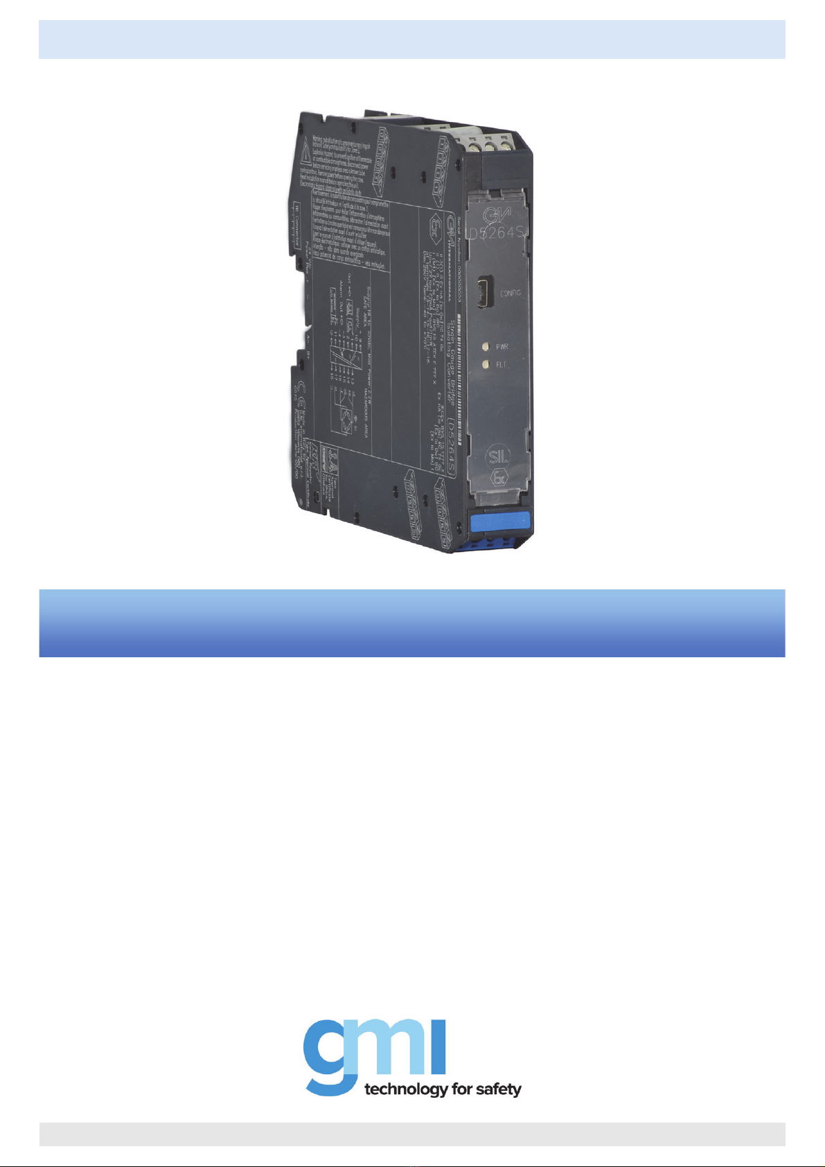
D5264 - SIL 2 Load Cell/Strain Gauge Bridge Isolating Converter G.M. International ISM0228-10
2
General Description:
The single channel DIN Rail Load Cell/Strain Gauge Bridge Isolating Converter D5264S module is a unit suitable for applications requiring SIL 2 level (according to IEC 61508:2010) in
safety related systems for high risk industries.
The unit acts as a galvanically isolated interface installed between a PLC/DCS in Safe Area and a load cell (or a group of load cells) in Hazardous Area. Up to four 350 Ωload cells, or
five 450 Ωload cells, or ten 1000 Ωload cells can be connected in parallel. It provides a fully floating power supply voltage with remote sensing capabilities to load cells located in
Hazardous Area and converts the mV signal from the load cell into a 0/4-20 mA, providing both current source and sink capabilities. The module is also provided with PhotoMOS alarm
output. A modbus output is also provided to interface the PLC/DCS using digital communication.
Automatic Calibration: Automatic calibration can be accomplished in the field without disconnecting the unit.
Function: 1 channel I.S. input from strain gauge signals, provides 3 port isolation (input/output/supply) and current (source or sink mode) output signal. A modbus output is also provided
to interface digital device.
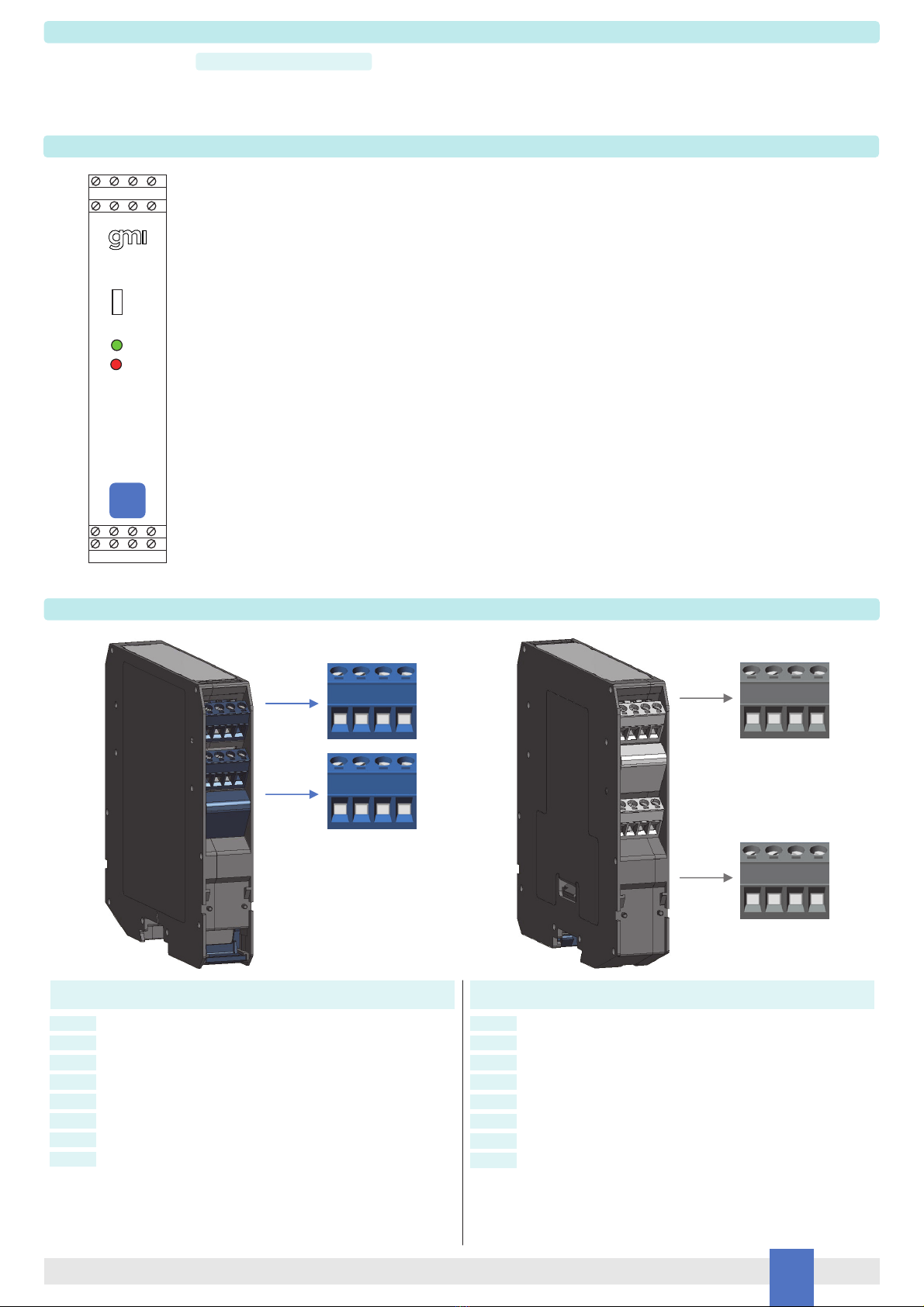
Signalling LED: Power supply indication (green).
Alarm indication (red).
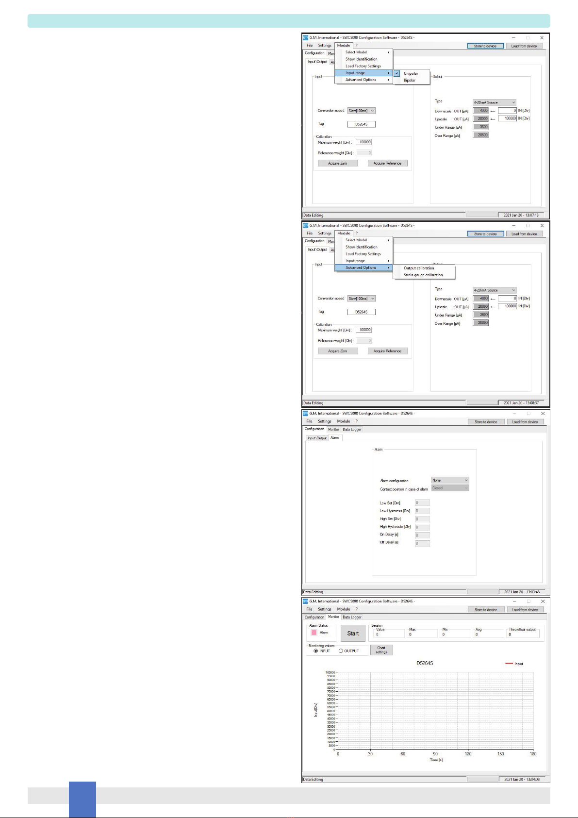
Configurability: Totally software configurable, no jumpers or switches, input calibration, mA source/sink output signal by GM PPC5092 Adapter and SWC5090 Configurator software.
A 16 characters tag can be inserted using the configuration software.
EMC: Fully compliant with CE marking applicable requirements.
Technical Data
Characteristics
Supply:
24 Vdc nom (18 to 30 Vdc) reverse polarity protected, ripple within voltage limits ≤5 Vpp.
Current consumption @ 24 V: 100 mA with four 350 Ωload cells connected and with 20 mA output typical.
Power dissipation: 2.1 W with 24 V supply voltage, four 350 Ωload cells connected and 20 mA output typical.
Max. power consumption: at 30 V supply voltage, short circuited input, overload condition, 2.2 W.
Isolation (Test Voltage):
I.S. In/Out 1.5 KV; I.S. In/Modbus Out 1.5 KV; I.S. In/Supply 1.5 KV; Out/Supply 500 V; Modbus Out/Supply 500 V; Out/Modbus Out 500 V;
Out/Alarm Output 500 V; Alarm Out/Modbus Out 500 V; Supply/Alarm Output 500 V
Input:
up to four 350 Ωload cells (parallel connection); up to five 450 Ωload cells (parallel connection); up to ten 1000 Ωload cells (parallel connection).
A/D Conversion time: 100 ms (slow acquisition mode) or 12.5 ms (fast acquisition mode).
Bridge supply voltage: 4.0 Vdc nominal.
Bridge output signal: 1 to 4 mV/V.
Line resistance compensation: ≤10 Ω.
Output: Fully customizable 0/4 to 20 mA, on max. 300 Ωload source mode, current limited at 24 mA. In sink mode, the external voltage generator range is V min. 3.5V at 0Ωload and V
max. 30V. If generator voltage Vg > 10 V, a series resistance ≥(Vg - 10)/0.024 Ωis needed. The maximum value of series resistance is (Vg - 3.5)/0.024 Ω.
Response time: ≤20 ms (10 to 90 % step).
Output ripple: ≤20 mVrms on 250 Ωload.
Modbus Output: Modbus RTU protocol up to 115.200 baud on Bus connector and terminals 11-12.
Alarm:
Trip point range: within rated limits of the input sensor.
Output: voltage free SPST photoMOS: 100 mA, 60 Vdc (≤1 V voltage drop).
Performance:
Ref. Conditions 24 V supply, 250 Ωload, 23 ± 1 °C ambient temperature.
Input:
Accuracy after autocalibration: ≤± 0.05 % of full scale.
Linearity accuracy: ≤± 0.02 % of full scale of input range.
Temperature influence: ≤± 0.002 % of full scale of input range for a 1 °C change.
Supply voltage influence: ≤± 0.002 % of full scale of input range for a min to max supply voltage change.
Analog Output:
Calibration accuracy: ≤± 0.05 % of full scale.
Linearity error: ≤± 0.05 % of full scale.
Supply voltage influence: ≤± 0.02 % of full scale for a min to max supply change.
Load influence: ≤± 0.02 % of full scale for a 0 to 100 % load resistance change.
Temperature influence: ≤± 0.01 % on zero and span for a 1 °C change.
Compatibility:
CE mark compliant, conforms to Directives:
2014/34/EU ATEX, 2014/30/EU EMC, 2014/35/EU LVD, 2011/65/EU RoHS.
Environmental conditions:
Operating: temperature limits –40 to + 70 °C, relative humidity max 95 % non condensing, up to 55 °C.
Storage: temperature limits – 45 to + 80 °C.
Max altitude: 2000 m a.s.l.
Safety Description:
ATEX: II 3(1) G Ex ec [ia Ga] IIC T4 Gc, II (1) D [Ex ia Da] IIIC, I (M1) [Ex ia Ma] I; IECEx: Ex ec [ia Ga] IIC T4 Gc, [Ex ia Da] IIIC, [Ex ia Ma] I
EAC-EX: 2Ex nA [ia Ga] IIC T4 Gc X, [Ex ia Da] IIIC, [Ex ia Ma] I
CCC: Ex nA [ia Ga] IIC T4 Gc, [Ex ia Ga] IIC, [Ex iaD]
CML: Ex nA [ia Ga] IIC T4 Gc, [Ex ia Da] IIIC
associated apparatus and non-sparking electrical equipment.
Uo/Voc = 7.2 V, Io/Isc = 177 mA, Po/Po = 471 mW at terminals 13-14-15-16-17-18.
Um = 250 Vrms, -40 °C ≤Ta ≤70°C.
Approvals:
TUV 15 ATEX 170897 X conforms to EN60079-0, EN60079-7, EN60079-11. IECEx TUN 16.0005X conforms to IEC60079-0, IEC60079-7, IEC60079-11.
RU C-IT.EX01.B.00018/19 conforms to GOST 31610.0,GOST 31610.11, GOST 31610.15.
CCC 2020322316000978 conforms to GB3836.1, GB3836.4; GB3836.8, GB12476.1, GB12476.4.
CML 20JPN2136X for CML approval.
DNV No.TAA00001U0 and KR No.MIL20769-EL002 for maritime applications.
SIL 2 conforms to IEC61508:2010 Ed.2 for analog current output and for alarm output.
Mounting:
EN/IEC60715 TH 35 DIN-Rail, with or without Power Bus or on customized Termination Boards.
Weight: about 160 g.
Connection: by polarized plug-in disconnect screw terminal blocks to accomodate terminations up to 2.5 mm2(13 AWG).
Location: installation in Safe Area or Zone 2, Group IIC T4.
Protection class: IP 20.
Dimensions: Width 22.5 mm, Depth 123 mm, Height 120 mm.