7
D1062 - Vibration Transducer InterfaceG.M. International ISM0094-7
D1062 is an isolated Intrinsically Safe Associated Apparatus installed into standard EN50022 T35 DIN Rail located in Safe Area/ Non Hazardous Locations or Zone 2, Group IIC,
Temperature Classification T4, Class I, Division 2, Groups A, B, C, D, Temperature Code T4 and Class I, Zone 2, Group IIC, IIB, IIA Temperature Code T4 Hazardous Area/Hazardous
Locations (according to EN/IEC60079-15, FM Class No. 3611, CSA-C22.2 No. 213-M1987, CSA-E60079-15) within the specified operating temperature limits Tamb -20 to +60 °C,
and connected to equipment with a maximum limit for AC power supply Um of 250 Vrms.
Non-incendive field wiring is not recognized by the Canadian Electrical Code, installation is permitted in the US only.
For installation of the unit in a Class I, Division 2 or Class I, Zone 2 location, the wiring between the control equipment and the D1062 associated apparatus shall be accomplished
via conduit connections or another acceptable Division 2, Zone 2 wiring method according to the NEC and the CEC.
Not to be connected to control equipment that uses or generates more than 250 Vrms or Vdc with respect to earth ground.
D1062 must be installed, operated and maintained only by qualified personnel, in accordance to the relevant national/international installation standards
(e.g. IEC/EN60079-14 Electrical apparatus for explosive gas atmospheres - Part 14: Electrical installations in hazardous areas (other than mines), BS 5345 Pt4, VDE 165,
ANSI/ISA RP12.06.01 Installation of Intrinsically Safe System for Hazardous (Classified) Locations, National Electrical Code NEC ANSI/NFPA 70 Section 504 and 505,
Canadian Electrical Code CEC) following the established installation rules, particular care shall be given to segregation and clear identification of I.S. conductors from non I.S. ones.
De-energize power source (turn off power supply voltage) before plug or unplug the terminal blocks when installed in Hazardous Area/Hazardous Locations or
unless area is known to be nonhazardous.
Warning: substitution of components may impair Intrinsic Safety and suitability for Division 2, Zone 2.
Explosion Hazard: to prevent ignition of flammable or combustible atmospheres, disconnect power before servicing or unless area is known to be nonhazardous.
Failure to properly installation or use of the equipment may risk to damage the unit or severe personal injury.
The unit cannot be repaired by the end user and must be returned to the manufacturer or his authorized representative. Any unauthorized modification must be avoided.
Warning
Operation
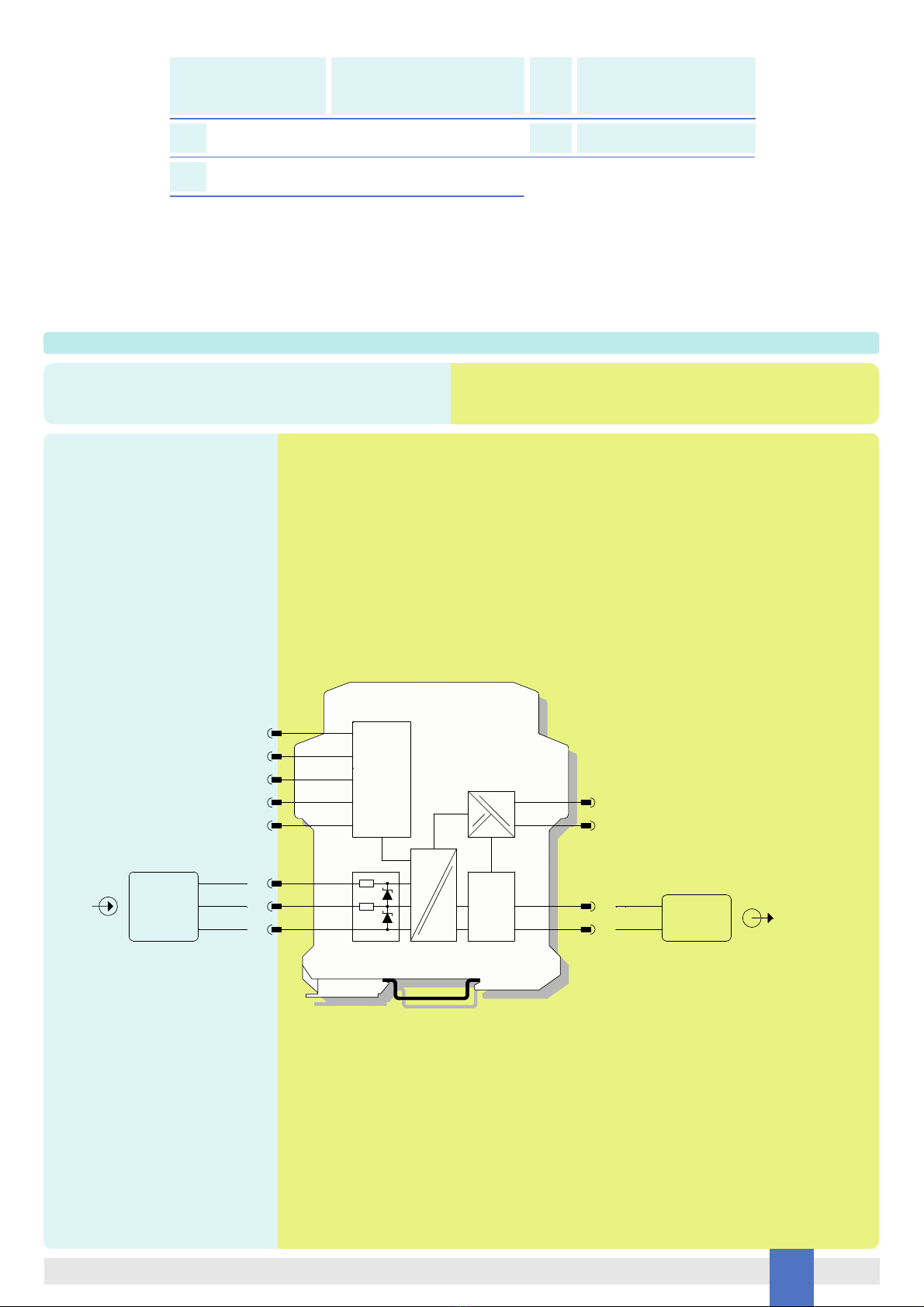
D1062 provides fully floating DC supply for energizing vibration transducer, accelerometers or 2-3 wires sensors located in Hazardous Area, and repeats the sensor input voltage in
a totally isolated circuit located in Safe Area to drive vibration monitors or analyzers for rotating machinery control and supervision purposes.
The circuit provides 3 port isolation (input / output / supply) and a “POWER ON” green led is lit when input power is present.
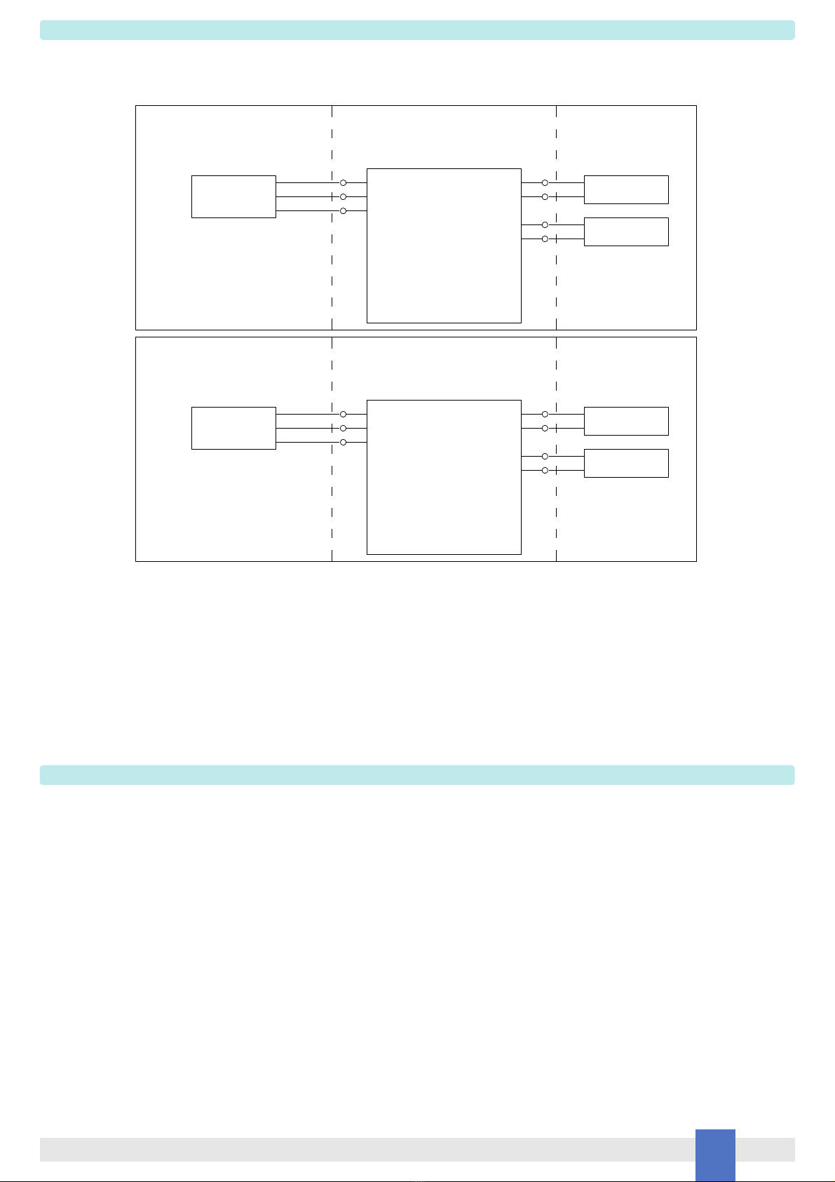
D1062 Associated Apparatus
FM Approved
under Entity Concept
and non-incendive field wiring
Unclassified Locations or
Hazardous (Classified) Locations
Class I, Division 2, Groups A, B, C, D, T-Code T4
Class I, Zone 2, Group IIC, IIB, IIA, T-Code T4
FM Approved under Entity Concept,
or third party approval
Hazardous (Classified) Locations
Class I, Division 1, Groups A, B, C, D
Class II, Division 1, Groups E, F, G
Class III, Division 1
Class I, Zone 0, Group IIC, IIB, IIA
Must not use or generate
more than 250 Vrms or Vdc
Unclassified Locations
Unclassified Locations or
Hazardous (Classified) Locations
Class I, Division 2, Groups A, B, C, D, T-Code T4
Class I, Zone 2, Group IIC, IIB, IIA, T-Code T4
Hazardous (Classified) Locations
Class I, Division 2, Groups A, B, C, D
Class II, Division 2, Groups E, F, G
Class III, Division 2
Class I, Zone 2, Group IIC, IIB, IIA
FM Approved under non-incendive field
wiring (permitted only for US installations),
or third party approval
Unclassified Locations
-
+
Power Supply
3
4
Must not use or generate
more than 250 Vrms or Vdc
D1062 Associated Apparatus
FM Approved
under Entity Concept
and non-incendive field wiring
2
1
-
-Control
Equipment
2-
4
3
-
+
1+Control
Equipment
Power Supply
Intrinsically
Safe Equipment
-
-
-
14
16
15
Non-Incendive
Equipment
-15
-16
-14