Characteristics: Technical Data:
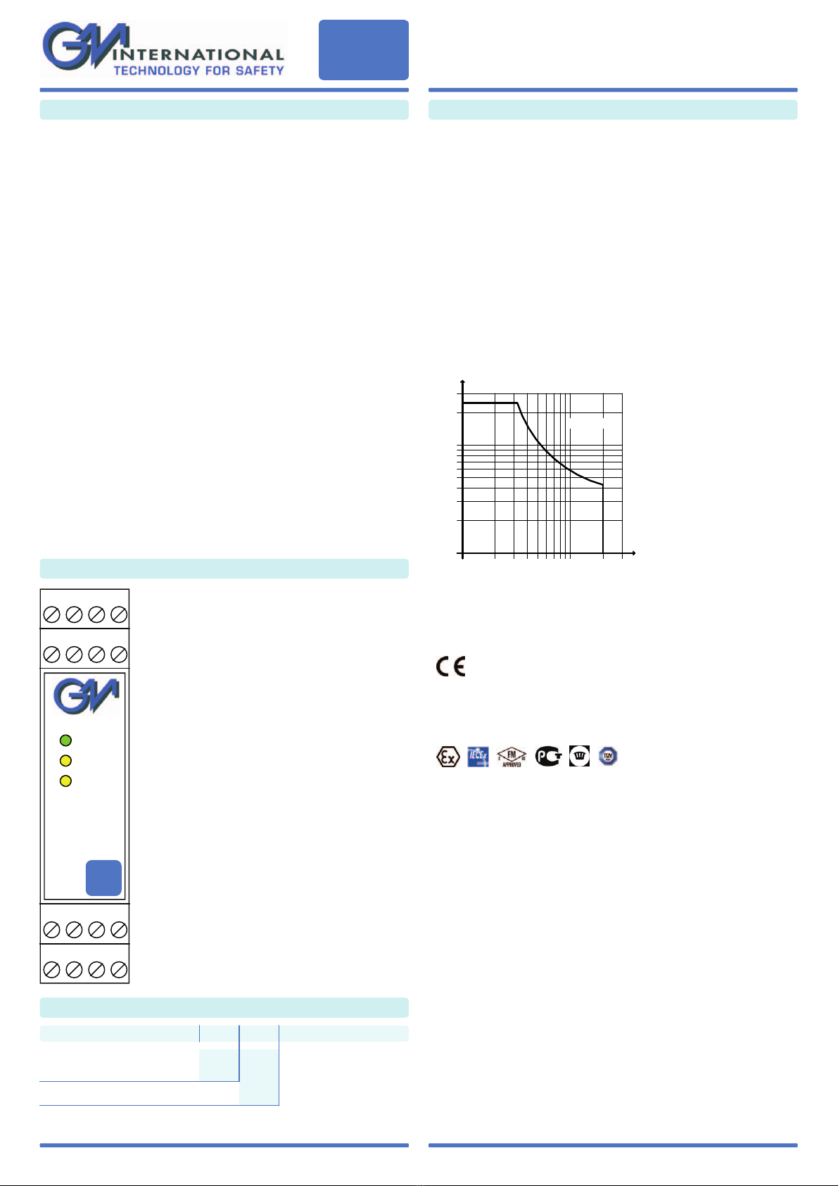
Front Panel and Features:
Ordering Information:
Model: D1044
D1044
D1044 SIL 2 - SIL 3 Digital Relay Output
Loop / Bus Powered DIN-Rail
Models D1044S, D1044D
General Description:
The single and dual channel DIN Rail Digital Relay Output, D1044S and D1044D,
are digital output modules enabling a Safe Area contact, logic level or drive signal,
to control a device in Hazardous Area, providing 3 port isolation (input/output/supply).
Outputs are galvanically isolated and inputs are depolarized to ease wiring operations.
Typical applications include switching of Hazardous Area circuits, changing of polarities
and sounder tones, calibrating of strain gauge bridges, resetting of field devices,
testing of fire detectors.
Each input channel can be isolated from supply (Bus Powered mode) or externally
connected (by wiring) to supply (Loop Powered mode, where the safety PLC directly
supplies the module and its input channel).
Each output channel provides a SPDT relay, with two contacts defined
NO (Normally Open) and NC (Normally Close) when the output relay is de-energized.
Considering each channel NE (Normally Energized), the output relay is energized,
so that NO contact is closed (useful for NE loads or Hazardous Area circuits) and
NC contact is open (useful for ND loads or Hazardous Area circuits). The safe state is
reached when the channel and the output relay are de-energized, so that NO contact is
open (de-energizing loads or Hazardous Area circuits) and NC contact is closed
(energizing loads or Hazardous Area circuits).
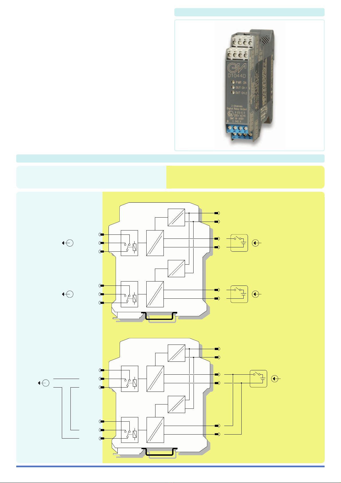
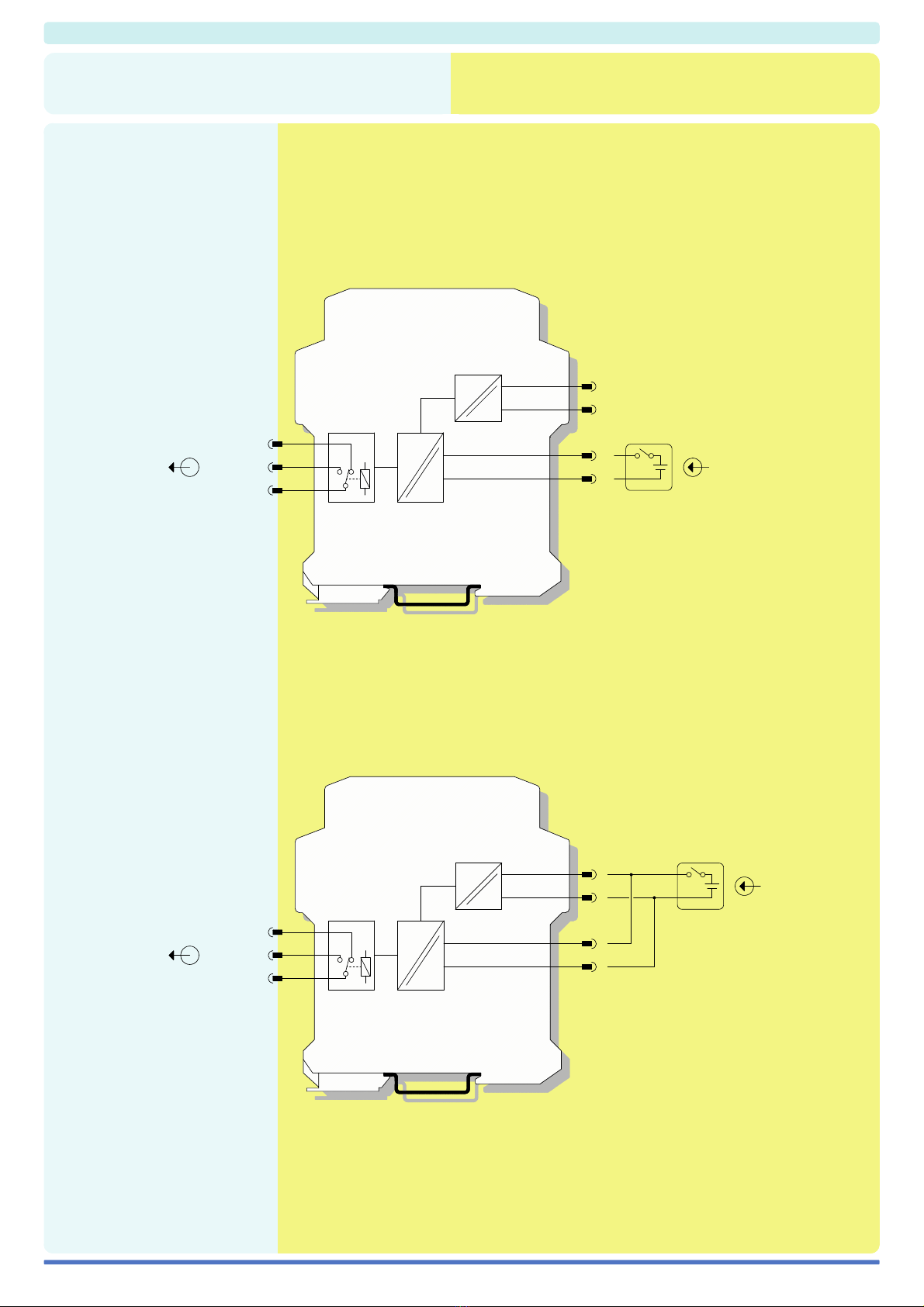
Function:
1 or 2 channels I.S. relay output, provides 3 port isolation (input/output/supply).
D1044S (Loop / Bus Powered mode) or D1044D (Bus Powered mode with
independent channels), as shown in function diagrams:
SIL 2 Safety Function for NE load (de-energized in safe state) is available at
Terminal Blocks 9/10-11 and Terminal Blocks 13/14-15.
SIL 2 Safety Function for ND load (energized in safe state) is available at
Terminal Blocks 12-11 and Terminal Blocks 16-15.
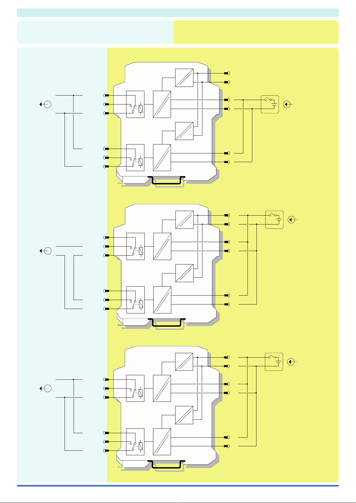
D1044D (Loop / Bus Powered mode with 1oo2 channel architecture),
as shown in function diagram:
SIL 3 Safety Function for NE load (de-energized in safe state) is available at
Terminal Blocks 13/14-11.
SIL 3 Safety Function for ND load (energized in safe state) is available at
Terminal Blocks 16-15 (or 12-11 because externally connected in parallel).
Signalling LEDs:
Power supply indication (green), output status (yellow).
EMC:
Fully compliant with CE marking applicable requirements.
• SIL 2 according to IEC 61508
D1044S or D1044D Bus Powered mode
for Tproof = 6 / 10 yrs (10 / 20 % of total SIF).
• SIL 2 according to IEC 61508
D1044S Loop Powered mode
for Tproof = 7 / 10 yrs (10 / 20 % of total SIF).
• SIL 3 according to IEC 61508
D1044S or D1044D Loop / Bus Powered mode
with 1oo2 channel architecture
for Tproof = 10 yrs (10 % or more of total SIF).
• PFDavg (1 year) 1.66 E-04, SFF 85.92 %
with single channel architecture.
• PFDavg (1 year) 8.32 E-06, SFF 99.59 %
with 1oo2 channel architecture.
• Output to Zone 0 (Zone 20), Division 1,
installation in Zone 2, Division 2.
• Voltage, contact, logic level input.
• Two SPDT Relay Output Signals.
• Three port isolation, Input/Output/Supply.
•
EMC Compatibility to EN61000-6-2, EN61000-6-4.
• ATEX, IECEx, FM & FM-C, Russian and
Ukrainian Certifications.
• High Reliability, SMD components.
• High Density, two channels per unit.
• Simplified installation using standard DIN Rail
and plug-in terminal blocks.
• 250 Vrms (Um) max. voltage allowed to the
instruments associated with the barrier.
Supply: 24 Vdc nom (20 to 30 Vdc) reverse polarity protected,
ripple within voltage limits ≤5 Vpp.
Current consumption @ 24 V: 55 mA for 2 channels D1044D,
35 mA for 1 channel D1044S with relays energized.
Power dissipation: 1.35 W for 2 channels D1044D, 0.85 W for 1 channel D1044S
with 24 V supply voltage and relays energized.
Max. power consumption: at 30 V supply voltage and relays energized,
1.5 W for 2 channels D1044D, 0.9 W for 1 channel D1044S.
Isolation (Test Voltage): I.S. Out/In 1.5 KV; I.S. Out/Supply 1.5 KV;
I.S. Out/I.S. Out 500 V; In/Supply 500 V; In/In 500 V.
Input: voltage free contact, logic level.
Trip voltage levels: OFF status ≤1.0 V, ON status ≥6.0 V (maximum 30 V).
Current consumption @ 24 V: 3 mA (≈10 KΩinput impedance).
Output I.S.: voltage free SPDT relay contact.
Contact material: AgNi90/10.
Contact rating: 60 Vdc, 2 A for use in Intrinsic Safety applications,
2 A 250 Vac 500 VA, 2 A 250 Vdc 80 W (resistive load) for non Intrinsic Safety applications.
DC Load breaking capacity:
Mechanical / Electrical life: 15 * 106/ 1 * 105operation, typical.
Operate / Release time: 5 / 2 ms typical.
Bounce time NO / NC contact: 1 / 5 ms.
Response time In / Out: 20 ms.
Frequency response: 10 Hz maximum.
Compatibility:
CE mark compliant, conforms to 94/9/EC Atex Directive and to
2004/108/CE EMC Directive.
Environmental conditions:
Operating: temperature limits -20 to + 60 °C,
relative humidity max 90 % non condensing, up to 35 °C.
Storage: temperature limits – 45 to + 80 °C.
Safety Description:
II (1) G [Ex ia Ga] IIC, II (1) D [Ex ia Da] IIIC, I (M1) [Ex ia Ma] I, II 3G Ex nA IIC T4,
[Ex ia Ga] IIC, [Ex ia Da] IIIC, [Ex ia Ma] I associated electrical apparatus.
Uo/Voc = 0 V, Io/Isc = 0 mA, Po/Po = 0 mW at terminals 13/14-15-16, 9/10-11-12
(Uo, Io, Po equal to the connected Intrinsic Safety circuit).
Ui/Vmax = 60 V, Ii/Imax = 2 A, Ci = 0 nF, Li = 0 nH at term. 13/14-15-16, 9/10-11-12.
Um = 250 Vrms, -20 °C ≤Ta ≤60 °C.
Approvals:
DMT 01 ATEX E 042 X conforms to EN60079-0, EN60079-11, EN60079-26,
EN61241-0, EN61241-11, IECEx BVS 07.0027X conforms to IEC60079-0,
IEC60079-11, IEC60079-26, IEC61241-0, IEC61241-11,
GM International CRR028 conforms to EN60079-0, EN60079-15,
FM & FM-C No. 3024643, 3029921C, conforms to Class 3600, 3610, 3611, 3810 and
C22.2 No.142, C22.2 No.157, C22.2 No.213, E60079-0, E60079-11, E60079-15.
Russia according to GOST 12.2.007.0-75, R 51330.0-99, R 51330.10-99 [Exia] IIC X.
Ukraine according to GOST 12.2.007.0, 22782.0, 22782.5 Exia IIC X.
TUV Certificate No. C-IS-204194-01, SIL 2 / SIL 3 conforms to IEC61508.
Please refer to Functional Safety Manual for SIL applications.
Mounting: T35 DIN Rail according to EN50022.
Weight: about 140 g D1044D, 120 g D1044S.
Connection: by polarized plug-in disconnect screw terminal blocks to accomodate
terminations up to 2.5 mm2.
Location: Safe Area/Non Hazardous Locations or Zone 2, Group IIC T4,
Class I, Division 2, Groups A, B, C, D Temperature Code T4 and
Class I, Zone 2, Group IIC, IIB, IIA T4 installation.
Protection class: IP 20.
Dimensions: Width 22.5 mm, Depth 99 mm, Height 114.5 mm.
1 channel S
G.M. International DTS0241-5 Page 1/4
1 2 3 4
16151413
Power Bus enclosure
2 channels D
/B
5 6 7 8
0.20.1
V (V)
I (A)
10
20
30
40
50
100
200
300
0.3 0.5 1 2 5
Resistive
Load
9 10 11 12
CH. 2
CH. 1
PWR ON
www.gmintsrl.com