GMT GMTCNT GOP42-150ATE User manual

1.1 Çevre Şartları
Cihazın montajı yapılırken, AC güç kablolarının, PLC çıkış modüllerinin, kontaktörlerin, rölelerin
ve buna benzer diğer elektriksel birimlerin cihazın arka bölgesinden uzakta olmasına özen
gösterilmelidir. Çalışma sıcaklığı -10…60 C dir.
1.2 Güç Gereksinimleri
Giriş gerilimi: 21~28VDC; Başlangıç akımı:180mA;İşletim akımı:130mA.
Ürün ve konverterler veya kesintisiz güç kaynağı arasında yeterli mesafe olmalıdır. Bu tarz
cihazların giriş çıkışlarında ekranlı kablo kullanıldığına ve bunların da topraklama hattına
bağlı olduğuna emin olunuz.
DC kaynaklar ana AC güç kaynağından izole edilmelidir.
Sürekli yük veya kontrol cihazının giriş devresi ile ortak güç kullanmayınız.
Not: İçerdeki sigorta aşırı gerilim durumunda cihazın zarar görmesini önleyecektir. Ancak,
içerdeki elektronik parçaların zarar görmeyeceği garanti edilmemektedir.
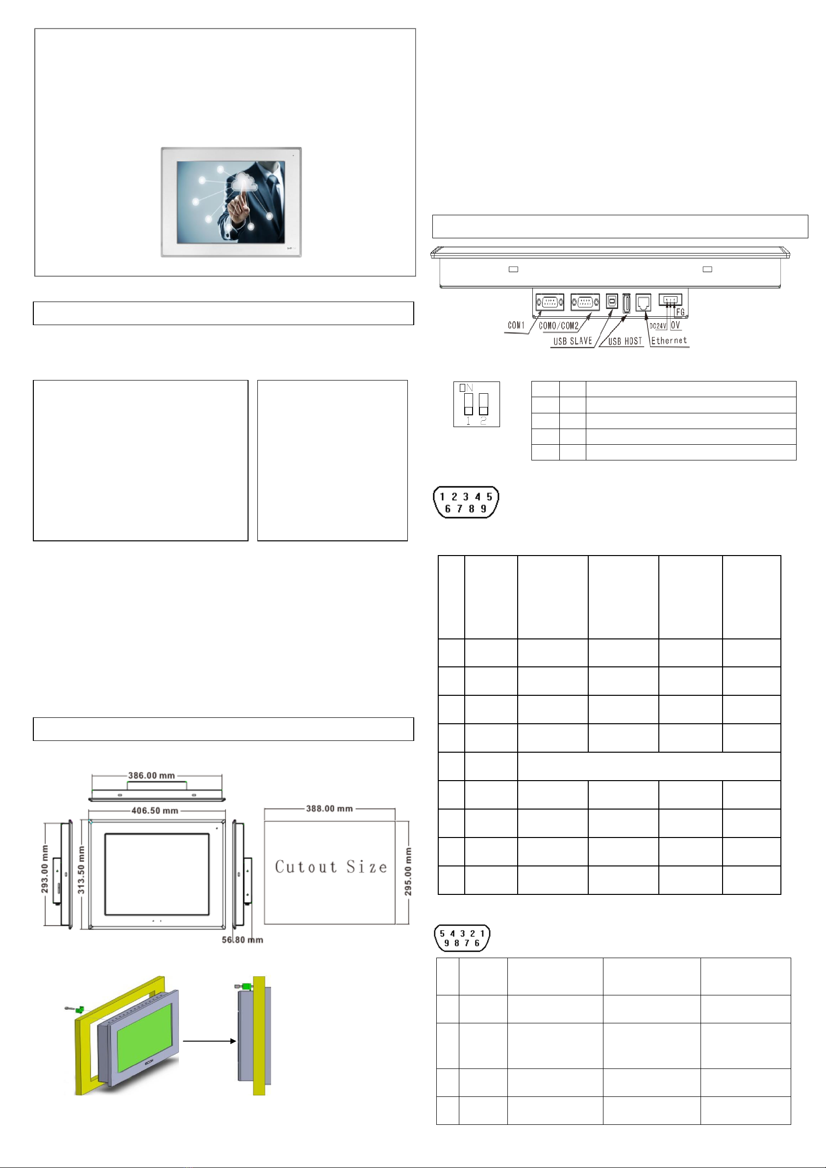
2.1 Ebarlar(mm)
2.2 Montaj Talimatları
2.3 Güç Bağlantıları
Güç kaynağı kabloları için lütfen güvenlik şartnamelerine uygun olan dielektrik değere ve akım
değerlerine sahip kablolar seçiniz. Güç terminalleri paketleme kutularının içerisinde paketlenmiş
haldedir.
DC hattının artısını ‘DC24V’ terminaline ve eksisini de ‘GND’ terminaline bağlayınız.
3.1 DIP Switch
3.2 COM0/COM2
9 pinli erkek D-SUB’un COM0’a bağlantısı. Bu port cihazı RS–232/485/422
kontrolöre bağlamak için kullanılır. Not: RS–232/485/422 haberleşme
fonksiyonları COM0 ile desteklenmiştir.
COM2 RS232 haberleşme fonksiyonunu destekler ve yalnızca RS232 kontrolörüne
bağlanmakla kalmaz aynı zamanda operatör panelinin programlanması ve hata ayıklama
fonksiyonun çalıştırılması için de kullanılır.
Pin
Sembol
COM0
PLC
[RS-485]4kablo
COM0
PLC
[RS-485]2kablo
COM0
PLC
[RS-232]
COM2
PLC/PC
RS-232]
1
Rx-(B)
RS-485 Rx
RS485 B
2
RxD_PLC
RS-232 Rx
3
TxD_PLC
RS-232 Tx
4
Tx-
RS-485 Tx
5
GND
Toprak
6
Rx+(A)
RS-485 Rx
RS485 A
7
RxD_PC
RS-232 Rx
8
TxD_PC
RS-232 Tx
9
Tx+
RS-485 Tx
3.3 COM1 9 pinli erkek D-SUB’un COM0’a bağlantısı. Bu port cihazı RS–232/485/422
kontrolöre bağlamak için kullanılır.
Pin
Sembol
PLC [RS-485]4
PLC [RS-485]2
PLC [RS-232]
1
Rx-(B)
RS-485 Rx
RS485B
2
RxD_PLC
RS-232 Rx
3
TxD_PLC
RS-232 Tx
4
Tx-
RS-485 Tx
5
GND
Toprak
6
Rx+(A)
RS-485 Rx
RS485A
7
CTS_PLC
8
RTS_PLC
9
Tx+
RS-485 Tx
3.4 Ethernet
Ethernet interface can adaptive 10 M/ 100 M.
Bağlantı
Bu port standart ethernet kablosu (RJ-45 düz kablo) ile HUB ya da
anahtara, sonra da LAN’a bağlanır. Aynı zamanda bilgisayarın
Ethernet portuna crossover kablosu (RJ-45 çapraz kablo) ile de
bağlanabilir.
Port
Fonksiyonu
Program download/upload ve On-line simülasyon yapılabilir. Bir
operatör paneli ağında birden fazla operatör paneline bağlanılabilinir.
port.
3.5 USB HOST
Bağlantı
USB disk ya da USB ara yüzü ile bağlayınız.
Port
Fonksiyonu
USB klavye, mouse ve yazıcı bağlanabilir. USB diske veri depolanabilir.
USB disk üzerinden program upload/download yapılabilir.
3.6 USB SLAVE
3.7 SD KART
Bağlantı
Standart SD kart ara yüzü ile bağlayınız.
Port Fonksiyonu
SD karta veri depolanabilir. SD kart üzerinden program download
/upload yapılabilir.
GMT Endüstriyel Elektronik San. ve Tic. Ltd. Şti.
Kavacık Mah. Yurtsever Sk. No:2 Beykoz / İstanbul -Turkey
Tel : +90 216 668 0006 Pbx. Fax : +90 216 668 0008
url : www.gmtcontrol.com
SW1
SW2
Çalışma modu
ON
ON
Sistem ayar modu
OFF
ON
Dokunmatik ekran kalibrasyon modu
ON
OFF
Yazılım yenileme ve temel parametre ayar modu
OFF
OFF
Uygulama (çevrim içi çalışma) modu
Bağlantı
Standart USB kablosu ile bilgisayara bağlayınız.
Port Fonksiyonu
Program download/upload yapılabilir.
GMTCNT GOP42-150ATE
Human Machine Interface
Installation Instruction
1.Kurulum Hakkında Notlar
2.Montaj Açıklamaları
Elektriksel, elektrostatik
veya elektromanyetik
gürültünün bulunduğu
Güç kayanağına yakın
ortamlarda ekranlama yapınız.
Doğrudan güneş ışığının alındığı
Hızlı sıcaklık değişiminin veya yüksek nemin
olduğu
Patlama tehlikesi olan
Yanıcı gazların bulunduğu
Buharlı ve tozlu
Sarsıntılı veya titreşimli
ortamlarda kullanmayınız.
gas
Places of much dust, dirt, salt and iron powder
Places that will be splashed water, oil and drugs
Places that bring direct vibration and shock to
host
3. Bağlantı Diyagramı
Cihazı yuva kesiti içerisine yerleştiriniz. Kutunun
etrafındaki 4 adet tutturma aparatını kaydırın. Vidaları eşit
bir şekilde, operatör panelin içine sağlam bir şekilde
tutturulduğunda emin oluncaya kadar sıkınız
NEMA–4 özelliklerinin ayarlarını yapmak için, tüm montaj
aparatları kullanılmalıdır ve panel eğilmemelidir.
Montaj aparatlarını aşırı derecede sıkmayınız.

1.1 Environmental Requirement
Please make sure that AC power, PLC output modules,starters,relays and other types of
electrical interface device are far away from the back of this product.
1.3 Power Requirement
Input voltage: 12~28VDC; Starting current:180mA;Working current:130mA.
Particularly note that there must be enough distance between this product and converters
or switch mode power supply. Make sure that the input and output cables of that kind
equipment are shield cable and the shielding network is connected with the ground.
Make sure that the DC power andAC power is isolated.
Do not use common power with perceptual load or input circuit of the controller.
NOTE:
An Internal fuse will prevent damage for over voltage condition, however it isn’t guaranteed
the internal electronic components are not damaged.
Chassis ground must be used.
2.1 Dimensional Drawing (mm)
2.2 Fixed Screw Installation Instructions
Put the unit through the panel cut out. Slide the clamps into the 4 holes provided around the
case. Tighten the clamping screws in an even pattern until the unit is secured in the panel.
To seal to NEMA-4 specifications, all supplied mounting clamps must be used and panel
cannot flex more than 0.010"
Do not over-tighten mounting clamps!
2.3 Power Connections
Before connecting the power, please make sure all local and national electrical standards are
met. For power cables, please select cables with their dielectric strength values and current
values in compliance with the safety specifications.
First find the power terminal at the back of the product and loosen the screw according to
counterclockwise, then insert the power cables and tighten the screw up.
Connect positive DC line to the ‘+24V’ terminal and the DC ground to the ‘0V’ terminal.
3.1 DIP Switch
3.2 COM0&COM2
Pin assignment of the 9-pin male,D-SUB,COM0.This port is used to
connect the GOP41-070ET(E) to controller with RS-232/485/422 port.
Note: RS232/485/422 communication functions are supported by
COM0.COM2 supports RS232 communication function.
Pin
Signal
COM0
PLC
[RS-485]4wire
COM0
PLC
[RS-485]2wire
COM0
PLC
[RS-232]
COM2
PC/PLC
[RS-232]
1
Rx-(B)
RS-485 Rx
RS485 B
2
RxD_PLC
RS-232 Rx
3
TxD_PLC
RS-232 Tx
4
Tx-
RS-485 Tx
5
GND
Signal Ground
6
Rx+(A)
RS-485 Rx
RS485 A
7
RxD_PC
RS-232 Rx
8
TxD_PC
RS-232 Tx
9
Tx+
RS-485 Tx
3.3 COM1
Pin assignment of the 9-pin female, D-SUB, COM1. This port is used to
connect the MT4523 series to controllers with RS-232/485/422 port.
Pi
n
Signal
PLC [RS-485]4 wire
PLC [RS-485]2 wire
PLC [RS-232]
1
Rx-(B)
RS-485 Rx
RS485B
2
RxD_PL
C
RS-232 Rx
3
TxD_PLC
RS-232 Tx
4
Tx-
RS-485 Tx
SW1
SW2
Working Mode
ON
ON
System Setting Mode
OFF
ON
Touch Screen Calibrate Mode
ON
OFF
Firmware Update and Basic Parameter Setting Mode
OFF
OFF
Application (Online Operation) Mode
GMTCNT GOP42-150ATE
Human Machine Interface Operatör Panel
Kurulum Talimatları
1.Installation Note
2. Installation Description
Please take shielding
measures in the following
places:
Places that exist electrostatic
or other kinds of noise
Places of strong
electromagnetic
Places that may be exposed
to rays
Places near the power
Please do not use in the following places:
Places direct in sunlight
Surrounding temperature and humidity beyond
the specifications
Places of temperature change sharply and
easily cause condensation
Places that exist corrosive gas and
combustible gas
Places of much dust, dirt, salt and iron powder
Places that will be splashed water, oil and
drugs
Places that bring direct vibration and shock to
host
3. External Interface

5
GND
Signal ground
6
Rx+(A)
RS-485 Rx
RS485A
7
CTS_PL
C
Clear to send input
8
RTS_PL
C
Ready to send
output
9
Tx+
RS-485 Tx
3.3 Ethernet
Connectio
n
This port is connected with the HUB or Switch through a standard
Ethernet cable (RJ-45 straight-through cable) and then connected to
a LAN. It can also be directlyconnected with the Ethernet port of a PC
through a dual system interconnection cable (RJ-45 crossover cable).
Port
Function
The port can be used for upload/download of HMI configuration,
setting of system parameters and online simulations of configurations.
It can connect multiple HMIs via the Ethernet to form an HMI network.
Furthermore, it can implement communications between HMI and
PLC via the Ethernet, as well as communications with a PC via the
Ethernet port.
3.4 USB HOST
Connection
Connect with USB interface devices or U disks
Port
Function
This interface can be connected with USB keyboard, mouse and printers,
and the U disk can be used for user’s configuration uploading/ downloading
as well as data storage.
3.5 USB SLAVE
3.6 SD CARD
Connection
Standard SD card interface
Port
Function
The SD Card can be inserted in through this interface for Data storage and
user configuration uploading/downloading.
Connection
USB Slave port can be connected with a PC
Port
Function
The port is only used to download user configuration program to the
HMI and to set HMI system parameters.
Table of contents
Languages: