manuals.online logo
Brands
  1. Home
  2. •
  3. Brands
  4. •
  5. GMTCNT
  6. •
  7. DC Drive
  8. •
  9. GMTCNT GSTD2860 User manual

GMTCNT GSTD2860 User manual

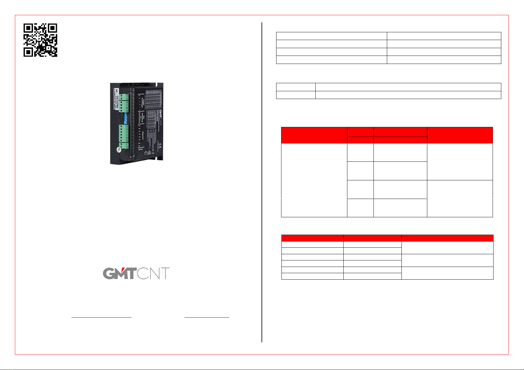
GMTCNT STEPPER MOTOR DRIVER
MODEL: GSTD2860
User Guide
GMT ENDÜSTRİYEL ELEKTRONİK SAN. VE TİC. LTD. ŞTİ.
Çubuklu Mahallesi Boğaziçi Caddesi No:6/B 34805 Beykoz / İstanbul / Türkiye
T +90 (216) 668 00 06 F +90 (216) 668 00 03
Web site: http://www.gmtcontrol.com/ E-Mail: gmt@gmtcontrol.com
1. Technicial Specifications
Main Supply Voltage
18-80VAC / 24-110VDC
Current
8.4A
Input Frequency
250kHz
Operation Temperature
Between 0°C ile +65°C
2. Stepper Driver LED Status
Green LED
It lights up when the device is energized.
Red LED
It lights up when the drive is faulty or the motor is not connected.
3. Stepper Driver Ports
3.1 Stepper Driver Power and Motor Connection Port
Stepper Drive Inputs
AC1
Power Input
STEP DRIVER FEED INPUTS
(18- 80VAC/24-110VDC)
AC2
Power Input
Stepper Motor Cables
Connection Pins
A+
Stepper Motor
Connection Input
Phase A+
Motor Phase A
A-
Stepper Motor
Connection Input
Phase A-
B+
Stepper Motor
Connection Input
Phase B+
Motor Phase B
B-
Stepper Motor
Connection Input
Phase B-
3.2 Control Signal Input Ports
Symbol
Port name
Explanation
PLS+
Pulse signal +
Compatible with 5V and 24V
PLS-
Pulse signal -
DIR+
Direction signal +
Compatible with 5V and 24V
DIR-
Direction signal -
*ENA+
Enable signal +
Compatible with 5V and 24V
*ENA-
Enable signal -
*Enable Input: This input enables or disables the stepper motor driver. In factory settings, this input
comes in normally closed contact state and no external signal is required.
Attention !
Read the user manual carefully before using the device!
Responsibility for damages, losses and personal accidents caused by not following the warnings in
the user manual belongs to the user. In case of failure to comply with the instructions, the product
will be out of warranty.
3.3 Alarm Signal Output Port
You can find more detailed information about the connection of alarm outputs at our forum site,
http://forum.gmtcontrol.com/.
3.4 Control Signal Connection
4. Stepper Driver DIP Switch Settings
4.1 Current Switch Settings
Current Settings
Peak
RMS
SW1
SW2
SW3
2.1A
1.5A
0
0
0
3.15A
2.25A
1
0
0
4.03A
2.88A
0
1
0
4.78A
3.42A
1
1
0
5.69A
4.06A
0
0
1
6.44A
4.60A
1
0
1
7.35A
5.25A
0
1
1
8.4A
6.0A
1
1
1
4.2 Pulse Switch Settings
Resolution
SW5
SW6
SW7
SW8
400
1
1
1
1
800
0
1
1
1
1600
1
0
1
1
3200
0
0
1
1
6400
1
1
0
1
12800
0
1
0
1
25600
1
0
0
1
51200
0
0
0
1
1000
1
1
1
0
2000
0
1
1
0
4000
1
0
1
0
5000
0
0
1
0
8000
1
1
0
0
10000
0
1
0
0
20000
1
0
0
0
40000
0
0
0
0
4.3 Stall Current Switch Setting
SW4 is the switch that sets the current to be used by the stepper driver during stop.
If this switch is in the ON position, the current set in the reed switch will be the same as the current used in
the stepper driver. When turned OFF, the stepper drive uses half of the current set in the reed switch at
standstill.
5. Stepper Driver Dimensions (mm)
Symbol
Port name
ALM+
Alarm output +
ALM-
Alarm output -

Popular DC Drive manuals by other brands

Graco King E70 instructions

Graco

Graco King E70 instructions

GFA ELEKTROMAT SI 260.9-80,00 installation instructions

GFA

GFA ELEKTROMAT SI 260.9-80,00 installation instructions

ETC F-Drive R12 Series installation manual

ETC

ETC F-Drive R12 Series installation manual

Graham 1703 Series Installation, operation and maintenance manual

Graham

Graham 1703 Series Installation, operation and maintenance manual

DMG LUMIERE WDMX DRIVER user manual

DMG LUMIERE

DMG LUMIERE WDMX DRIVER user manual

Intelligent Motion Systems Excellence in Motion IM805H operating instructions

Intelligent Motion Systems

Intelligent Motion Systems Excellence in Motion IM805H operating instructions

Trinamic PANdrive PD-1140 Hardware manual

Trinamic

Trinamic PANdrive PD-1140 Hardware manual

ITEM LRE 8 D10 80x80 KGT Notes on Use and Installation

ITEM

ITEM LRE 8 D10 80x80 KGT Notes on Use and Installation

KLEE Drive MS Series manual

KLEE

KLEE Drive MS Series manual

TPG CA Series Operation manual

TPG

TPG CA Series Operation manual

Johnson Controls VSD II Series Installation Manual Addendum

Johnson Controls

Johnson Controls VSD II Series Installation Manual Addendum

SOMFY FREEVIA 600 Technical data sheet

SOMFY

SOMFY FREEVIA 600 Technical data sheet

ZIEHL-ABEGG Icontrol FXDM operating instructions

ZIEHL-ABEGG

ZIEHL-ABEGG Icontrol FXDM operating instructions

Phoenix Mecano DewertOkin DUOMAT 3 installation instructions

Phoenix Mecano

Phoenix Mecano DewertOkin DUOMAT 3 installation instructions

Danfoss vlt fcd 302 operating guide

Danfoss

Danfoss vlt fcd 302 operating guide

Sony DRU-880S operating instructions

Sony

Sony DRU-880S operating instructions

Toshiba TOSVERT VF-PS1 instruction manual

Toshiba

Toshiba TOSVERT VF-PS1 instruction manual

Viking ER20 Setup guide

Viking

Viking ER20 Setup guide

manuals.online logo
manuals.online logoBrands
  • About & Mission
  • Contact us
  • Privacy Policy
  • Terms and Conditions

Copyright 2025 Manuals.Online. All Rights Reserved.