GNB 93.10G User manual

®
INSTALLATION
&
OPERATING
INSTRUCTIONS
FOR TCXG TUBULAR
LEAD-CALCIUM BATTERIES
A Division of Exide Technologies
SECTION 93.10G 2014-09

YOUR GNB INDUSTRIAL POWER REPRESENTATIVE
SALESPERSON _________________________________
TELEPHONE____________________________________
LOCATION _____________________________________
GNB
SERVICE ASSISTANCE
1-800-241-4895

Page
SECTION 1
1.0 Safety ................................................................. 2
SECTION 2
2.0 Receiving Batteries ........................................2
SECTION 3
3.0 Storage...........................................................2
SECTION 4
4.0 Battery Assembly and Installation ..................2
4.1 Site .................................................................2
4.2 Ventilation.......................................................2
4.3 Temperature...................................................3
4.4 Electrolyte Level .............................................3
4.5 Cell Positioning...............................................3
4.6 Flash Arrestors ...............................................3
4.7 Contact Sufaces .............................................3
4.8 Electrical Connections....................................3
4.9 Connection Resistance ..................................3
4.10 Labels and Markings ......................................3
4.11 Initial Charge ..................................................3
SECTION 5
5.0 Equalizing Charge ..........................................4
SECTION 6
6.0 Specific Gravity ..............................................4
SECTION 7
7.0 Operation........................................................5
SECTION 8
8.0 Cell Voltage Variation.....................................5
SECTION 9
9.0 Water Addition................................................5
SECTION 10
10.0 Tap Connections ............................................5
SECTION 11
11.0 Pilot Bloc ........................................................5
SECTION 12
12.0 Records ..........................................................5
SECTION 13
13.0 Capacity Testing.............................................6
INDEX
Page
TABLES
TABLE A.................................................................4
TABLE B.................................................................4
TABLE C.................................................................5
STATIONARY BATTERY
MAINTENANCE REPORT......................................7
FIGURES
FIGURE 1 ...............................................................4

CAUTION! Before proceeding with the unpacking,
handling, installation and operation of a lead-acid storage
battery, the following general information should be reviewed
together with the recommended safety precautions.
A lead-acid battery is an electrochemical device that contains
electrolyte. The electrolyte is corrosive and can cause injury.
Lead-acid batteries, when installed, are capable of high
voltage that can cause electrical shocks to personnel.
All lead-acid batteries in the course of normal operation
generate gases that could be explosive.
SECTION 1
1.0 SAFETY
1.1 Follow your company’s safety instructions when working
with or near industrial lead-acid batteries. Thoroughly
familiarize yourself with industry and government guidelines
for charging, handling, and maintaining industrial batteries.
1.2 Assign battery and charger care to properly trained
personnel. The battery contains sulfuric acid. Avoid sulfuric
acid contact with skin, eyes, or clothing. Wear a rubber
apron, gloves, boots, and goggles or face shield when
handling, checking, filling, or charging batteries.
1.3 Keep water readily available for flushing spilled electrolyte
from eyes or skin. Obtain medical attention immediately.
1.4 Batteries produce hydrogen. Keep open flames away.
Do not check electrolyte level with a cigarette lighter or
match. Use a flashlight or permanent lights only. Do not
smoke or create sparks when working on batteries.
1.5 Platform lifts of adequate capacity to handle cell weights
and dimensions may be used provided they are stable and
capable of reaching needed heights and used on smooth
and level floor conditions.
1.6 Never lay metal tools, such as wrenches or other material
on top of batteries.
1.7 Insulate tool handles to protect against shorting.
1.8 Make sure that all battery connections are properly
prepared and tightened to prevent possible injury to personnel
or failure of system.
1.9 If acid is spilled on the floor, apply a strong neutralizer,
like baking soda. Check local regulations regarding disposal
of neutralized waste.
SECTION 2
2.0 RECEIVING BATTERIES
2.1 Immediately upon receipt of shipment, examine for
possible damage caused in transit. Damaged packing
material or staining from leaking electrolyte would indicate
rough handling. If such conditions are found, make notation
on delivery receipt before signing. If battery damage is found,
request an inspection by the carrier and file a damage claim.
Also notify your GNB®Industrial Power representative.
2.2 Shortly after receipt (within 15 days), examine all batteries
for concealed damage. Pay particular attention to packing
materials exhibiting damage or electrolyte staining. Perform
examination prior to installation and disposal of packing
materials. Examine cells for container damage, misaligned
elements, broken plates, or any other visible damage.
SECTION 3
3.0. STORAGE
3.1. If the battery is not to be installed at the time of receipt,
it is recommended that it be stored indoors in a cool [16°C
(60°F) to 32°C (90°F)], clean, and dry location. Do not top
load pallets as possible battery damage may occur.
3.2. Prior to planned installation of the battery, the accessory
parts should be opened and checked against shipping
invoice (or battery system drawings) for completeness.
Checking parts before storage will eliminate potential delays
during installation.
3.3. The storage interval from date of shipment to the date of
installation/initial charge should not exceed six (6) months.
(Assumes 77°F/25°C average storage temperature. Assume
three months maximum storage time for 90°F/32°C average
temperatures.) Storage beyond the stated period can result
in sulfated plates, which can be detrimental to battery life and
performance. Failure to store the battery in accordance with
the above recommendations may void the warranty.
SECTION 4
4.0 BATTERY ASSEMBLY
AND INSTALLATION
4.1 SITE
It is recommended that the battery be installed indoors in a
clean and dry location. The battery should be shielded from
direct sunlight, heating units or steam pipes as they can
cause temperature gradients in the electrolyte and negatively
impact battery performance. The floor should be level and
capable of supporting the weight of the batteries (and rack).
4.2 VENTILATION
All lead-acid batteries in the course of normal operation
generate gases that could be explosive. Ventilation should
be provided in the battery room to prevent hydrogen gas
from exceeding a concentration of 1%. Concentrations
above this value can result in an explosive mixture that can
be ignited by sparks from adjacent electrical equipment. All
air moved by ventilation should be exhausted to the outside
and not be allowed to re-circulate into other confined areas.
2

4.3 TEMPERATURE
A battery location having an ambient temperature of 25°C
(77°F) will result in optimum battery life. Batteries operated
above this temperature will suffer reduced life, while batteries
operated below this temperature may exhibit suppressed
capacity. Though brief temperature excursions between
0°C (32°F) and 40°C (104°F) can be tolerated, the normal
operating temperature is between 16°C (60°F) and 32°C
(90°F).
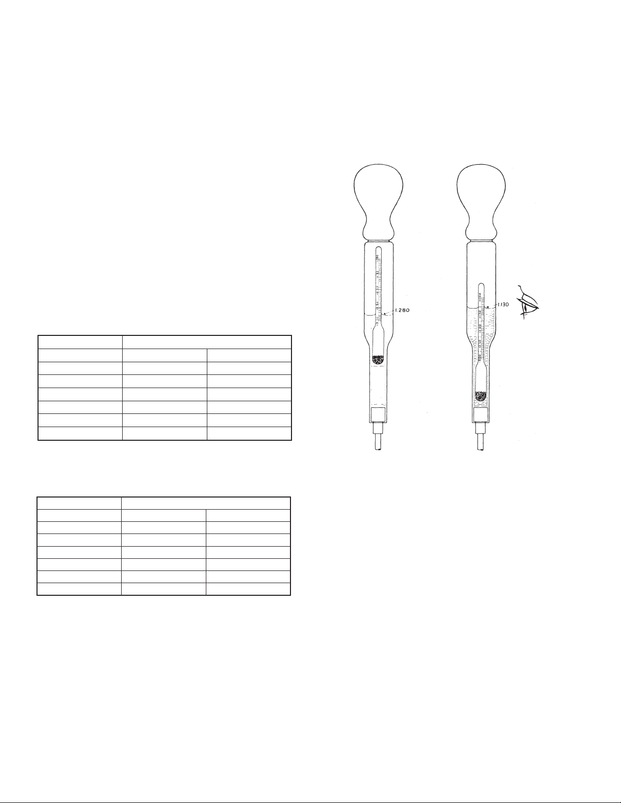
4.4 ELECTROLYTE LEVEL
During normal operation, the electrolyte level should be
between the high and low marks on the battery container.
Upon receipt of the battery, the electrolyte level may be a
bit lower than this mark; after charging, it may be higher.
The reason is that gas bubbles formed during charge will
adhere to the battery plates, displacing and raising the
electrolyte level. Do not attempt to adjust the electrolyte
either immediately upon receipt or immediately after the
initial charge.
4.5 CELL POSITIONING
By now, it is assumed that the rack has been assembled.
Determine the desired position of the positive and negative
terminals. Measure and mark the center of the rack.
Determine the number of battery blocks that will fit on a step/
tier of the rack. If that number is odd, position the centerline
of the first battery block on the centerline of the rack step/tier.
If the number is even, position the end of battery block on
the centerline of the rack step/tier. Work from the center out,
positioning the positive terminal next to the negative terminal
of the adjacent cell.
If a lubricant is needed to facilitate battery
positioning, use only Dow Corning 111.
Lubricants that contain solvents may damage
the battery containers and void warranty.
4.6 FLASH ARRESTORS
After the batteries have been positioned on the rack (but
before the inter-unit and inter-tier connections have been
made), replace the shipping caps with the provided flame/
flash arrestors.
4.7 CONTACT SURFACES
Gently clean the contact surfaces of the battery terminal
posts using a 3M Scotch Brite or similar scouring pad. Coat
the electrical contact surfaces lightly with provided No-Ox
grease.
4.8 ELECTRICAL CONNECTIONS
Install and torque the provided M8 stainless steel hardware
and torque the cell connector (or terminal plate) to the post.
Target connection torque is 100 - 110 inch-lbs. (11.3-12.0
N-m). Re-torque the stainless steel hardware 24 hours after
the initial tightening to account for relaxation of the lead-
hardware connection.
Electrical connections must be clean to minimize voltage drop
and prevent connector heating. If corrosion is observed, DO
NOT RE-TORQUE! The connection must be disassembled,
cleaned, neutralized, and then re-torqued.
Install the inter-tier cables as necessary. Do not connect
cables directly to the battery post. Utilize the terminal
plates provided for main terminal and inter-tier connections.
Re-check to be certain that the batteries are connected
positive terminal to negative terminal throughout the string.
Before connecting the battery string to the charger/load,
measure the total voltage at the battery terminals. The
voltage should be equal to the number of cells times the
voltage of one cell. For example, 60 cells times 2.09 volts
per cell = 125.40 volts (1.250 SG) or 60 cells times 2.05 volts
per cell = 123.0 volts (1.215 SG).
4.9 CONNECTION RESISTANCE
Connection resistance or micro-ohm (µΩ) measurements
should be taken at the time of installation and annually
thereafter. Initial measurements at installation become
benchmark values. Future values are compared to
this benchmark as an indication of connection integrity.
Re-torque of connections should be performed annually or
when connection resistance increases to more than 20%
over the benchmark value.
4.10 Labels and Markings
Numerals and polarity markings should not be applied
until after the cells have been installed on the rack. It is
recommended that they be applied to jar surfaces only, and
not to cell covers or rack rails.
2. Clean the plastic jar surface, in the area where the
numeral is to be located, by using a cloth dampened with a
washing soda solution. Immediately dry the area using a soft
dry cloth to remove residual washing soda.
CAUTION!! Do not use any solvent type materials as they
may cause damage to the plastic jar material.
3. It is a general practice to designate the positive terminal
cell as #1 with succeeding cells in series in ascending order.
4.11 INITIAL CHARGE
The first charge that the battery receives after shipping,
storage and installation is very important as it may affect the
life of the battery. Determine the maximum charge voltage
output that the charge system can provide and charge the
battery in the least amount of time possible according to
Table A. This maximum voltage divided by the number of
cells connected in series is the maximum charge voltage per
cell (VPC). If long periods of continuous charging are not
possible at the installation, (e.g. photovoltaic applications)
the battery should be charged where such capability exists.
The recommended times given in TABLE A are considered
minimum. Charge the cells until the charge current tapers
and stabilizes for 3 hours. Then, charge the battery for the
times and voltages given in TABLE A.
3
Table of contents
Other GNB Camera Accessories manuals

GNB
GNB Absolyte GX Series User manual

GNB
GNB GB3862 Manual

GNB
GNB Marathon Classic User manual

GNB
GNB Flooded Classic series Manual

GNB
GNB LiftForce User manual

GNB
GNB TUBULAR-LMX User manual

GNB
GNB Liftforce LPX 2.0 User manual

GNB
GNB KDZ User manual

GNB
GNB EPzS Series User manual

GNB
GNB Sonnenschein Product guide
Popular Camera Accessories manuals by other brands

Trojan
Trojan GC2 48V quick start guide

Calumet
Calumet 7100 Series CK7114 operating instructions

Ropox
Ropox 4Single Series User manual and installation instructions

Cambo
Cambo Wide DS Digital Series Main operating instructions

Samsung
Samsung SHG-120 Specification sheet

Ryobi
Ryobi BPL-1820 Owner's operating manual