Go Xpress 68 User manual

Copyright © 2018 Graphics One
Xpress 68
68"Industrial Oil Based 3-in-1 Calendar System
with Extension Table SUBLIMATION PRESSES
User’s Manual

Copyright © 2018 Graphics One
Catalogue
Chapter 1 Preface
1.1 Attention
1.2 Main technical data
Chapter 2 Brief introduction to products
2.1Model
2.2Directions to appearance and all parts
Chapter 3 Installation and connecting wire
3.1 Installation
3.2 Connecting wire
3.3 Electrical control schematic figure
Chapter 4 Operation & control
4.1 Normal operation of machinery part
4.2 Function illumination of operating key in control panel
Chapter 5 Elimination of frequent malfunction and maintenance
5.1 Eliminate of frequent malfunction
5.2 Current maintenance

Copyright © 2018 Graphics One
Chapter 1 Preface
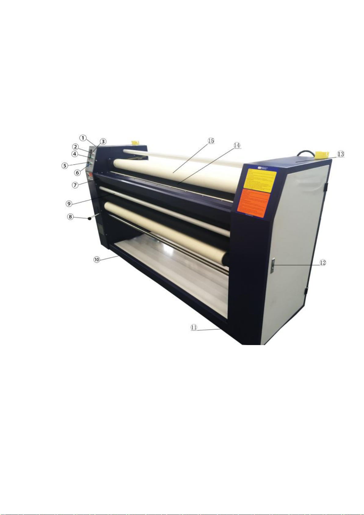
X-Press 68 is a type of rotary digital presses. It is adopted electric heating
diversion around oil layer, fast temperature rising, stable temperature on cylinder
surface, four shafts interlock, blanket disengaging mechanical structure. It is applied
for garment sheets, fabric rolls, flags, socks, blanket and curtain, ect.
1.1 Attention
A This manual offers installation, debugging, parameter set, trouble-shooting,
operation and attention. Please take care of this manual.
B Read this manual carefully before installation and debugging to avoid damage
and accident for mistake.
C User must select matched lead for power supply according to rating power of this
machine and install specially used leakage circuit breaker
D The outer of this machine must be earthing, or else, it will damage to human
beings.
E This machine must be equipped in ventilated, lightful environment at the vertical
direction .At least; there is1.5m space is around the machine.
F Immediately stop running to check the machine if abnormal situation occurs. At
the same time, the blanket should be out of cylinder, flow fan is helpful for cooling to
avoid damage of blanket.
G Operator must obey forbidden sign of all parts in this machine to operate.
HAs the equipment is heating machinery, there may be certain noises from the roller,
heating body or big/small bearings during the operation process, which is the normal
phenomenon and you may not worry about it;
I The control circuit plate and the transducer inside the machine case shall be kept
clean regularly with no dust or any other metal products fallen inside. Please do not
open the protection cover to avoid electric shock;
J The heating body, speed reducer and heat transfer oil etc of our company shall be
used for any replacement and please do not replace or rectify the equipment without
our permission.
K The external surfaces of heating tube are specially treated and do not use the

Copyright © 2018 Graphics One
corrosive liquid to clean it or put hard object inside to scratch the surfaces.
1.2 Main technical data
Model: 377-170-ET
Method of power supply: Three-phase and four-line
Input voltage: 380V/220V
Frequency: 50-60HZ
Rating power: 15KW ( motor power is 0.75KW)
Input current: 38A
Timing turn-off: 1-12 hours
Blanket: 1.73M(Width)×2.43M(Perimeter)
Machine: 2.27M(Length)×0.68M(Width)×1.27M(Height)
Total weight: about 650KG
Noise: 30QB
Above parameters should be changed with actual situation. Further Notice for change
partly is offered.

Copyright © 2018 Graphics One
Chapter 2 Brief introduction to product
2.1 Model
377-170-ET
2.2Explanation to appearance and all parts
⑴Left box
⑵Temperature control device
⑶General power supply button
⑷Heating button
⑸Frequency conversion controller
⑹Converter startup button
⑺Paper feeding (put-in) groove
⑻Hand knob for cloth fabric shaft
⑼Cloth fabric shaft
⑽Directional wheel
⑾Directional wheel

Copyright © 2018 Graphics One
⑿Door knob
⒀Right box
⒁Heating tube body
⒂Blanket
Configuration of inner right box
⑴Separate shaft
⑵Heating tube body shaft casing
⑶Pressing fabric shaft
⑷Balance shaft
⑸Pressing fabric synchronizing shaft
⑹Chain
⑺Motor
⑻Adjustable shaft
⑼Balance shaft
⑽Separate handwheel The blanket may be separate tube body or reset while in
rotation
⑾Separate reductor
⑿Overhaul manhole

Copyright © 2018 Graphics One
Inner configuration of left box
⑴Separate shaft
⑵Protection shaft
⑶Pressing fabric Shaft
⑷Balance shaft
⑸Pressing fabric synchronizing shaft
⑹Electric appliance control board
⑺Adjustable shaft
⑻Yoke electric ring(in protection cover)
⑼Balance shaft
⑽Separate synchronizing shaft
⑾Overhaul manhole

Copyright © 2018 Graphics One
Chapter 3 Installation and connecting wire
3.1 Installation
A Check that all screws in mainframe are loose or not, tighten if loose.
B The whole machine should be set at level with enough capacity; wood frame to
overhead the sliding wheel and level direction is preferred.
C This machine is used at environment of ventilating, dry, noncorrosive gas and no
inflammable and explosive material around the equipment.
D Matched load leakage circuit breaker separately on this machine with
3×6×6+1×4×4 international power wire. The crust of machine must be earthing
separately.
E Keep the equipment in level while installation. Use two section 160×160×700(length)
of bed timber under inner side of two wheel. Use level instrument to check if the
machine is level or not. When the working table is installed, the height must be
consistent with feeding blanket and level. The paper feeding (put in) shaft and cloth
feeding (put in) shaft must be of the same level with heating tank.
3.2 Connection wire
Block diagram of electric control main board
N
C
B
A

Copyright © 2018 Graphics One
4P R sJ zJ C
Input
∠
∠
∠
Output
Electrical heater Motor
3.3 Electrical control schematic figure
Electrical heater
Converter
0
0
0
0
0
0
0
0
0
0
0
0
0
0
0
0
0
0

Copyright © 2018 Graphics One
Chapter 4 Operation and control
4.1 Normal operation of mechanical part
Check if mechanical drive part is normal or not before working and then lift feeding
pressure beam to adjust the tension force of blanket. Start to work till qualified
temperature.
a. After confirming the good earthing and correct power wiring of the system, set the
breaker inside the case at on position, then press the button for “general power”,
then press the “VFC (Variable Frequency Control )Run”key on the VFC (Variable
Frequency Control )panel and adjust the frequency to the suitable position;
b.Press “heating”key to set the required temperature; which shall be decided
according to different fabrics of the customer. We propose that the user shall make
trial use by small size fabric and transfer paper when reaching the specified
temperature and make corresponding adjustment in case of over high or over low
temperature to ensure the quality of final product;
c.Put the fabrics and transfer paper on the fabric holder and paper holder on the
working table; when the temperature reaches the level for transfer printing, put the
fabrics on the table and lower down the press roller and let the fabrics enter the roller.
Note: the side of the transfer paper with ink shall face the fabrics and shall be placed
over the fabrics;
d.During the transfer printing process, the user may adjust the temperature in
accordance with the color of the printed pattern, or adjust the temperature by
controlling the speed of the tube.
e.Upon completion of the printing work, press “cooling down”key and turn the hand
wheel to remove the belt from roller; and the heating is stopped, when the
temperature decreases to 80℃, the equipment will be automatically stopped.
f. On special occasions ,Can turn off the "total power" and the " heating" button,
When host run after a given period to automatically shutdown, on normal occasions,
don’t recommend the use of this feature

Copyright © 2018 Graphics One
g Adjustment of blanket
①Power cabinet
②Adjustable core A
③Adjustable core B
④Electric control cable
For the affection of level and attraction force, the blanket in printing machine will be
drifting. The drifting adjustable core in this machine can be used as followings:
If the blanket drifts to right( to power cabinet),insert T type hex key wrench-set into
screw thread uropore in adjustable core A and then revolve at the direction of
anti-clockwise ,otherwise, if drift to left(to electric control cabinet, adjustable core B at
the direction of anti-clockwise .Note: this process is slow and patient.
h Usage of fabric shaft:
In order to material feeding easily, cloth-fabric shaft is equipped in this machine as
follows:
Use hand to flare-out fabric and paper under the green pressure rod .

Copyright © 2018 Graphics One
Attention: cloth and paper must be vertical to big rotary drum. Use hand to lift the
pressing fabric handle on electric control cabinet and then press on fabric by green
rod into machine. When rotary rod and blanket have seized cloth, use hand to low the
handle to make pressure beam hold on at air. Note: lift the cloth fabric beam when
cloth enter into big cylinder, or the cloth will be crimple.
4.2 Function illumination of operating key in control panel
See the picture of VFC(Variable Frequency Control)panel
1. Temperature control device. Client operates according to instruction of this device.
(Offered with the machine)
2. AC motor frequency conversion controller. Client operate according to instruction
manual of VFC(Variable Frequency Control).(Offered with machine)
3. Red color interlock button, press once to open (red lamp is light), press once
again to close(red lamp is off). This button is general switch of quadratic control
power supply and also used as rapid stop switch. If work is done, client must cut
off general power supply brake.
4. Green color interlock button, press once to open (green lamp is light), press once
again to close (green lamp is off). This button is used to control heating system.
5. This button is used to control converter of power supply, press this button and the
converter works. The display of converter control panel is original working state.
The panel can be set according to the need of client.

Copyright © 2018 Graphics One
Chapter 5 Elimination of Frequent Malfunction
and maintenance
5.1 Elimination method of Frequent Malfunction
Phenomenon
Cause
Elimination method
Temperature
can not be
higher or
heating slowly
Too small of inlet for power supply
and too big of voltage pressure drop
Replace the path of inlet in
power supply
Lack of phase or loose of
connections
Check three-phase output
voltage and tighten screw
Damage of tubular electric heating
element in heating unit
Replace the tubular electric
heating element in heating unit
Out of control or damage in
temperature device
Check and replace
temperature control device
Damage of solid relay
Check and replace solid relay.
Temperature
is out of
control
Breakdown of solid relay
Replace
The temperature control device is
out of control
Replace
Blanket
isen’t running
Blanket is too loose
Adjust the pressure
The bearing is jammed
Check and replace bearing
Failure of motor or reductor
Check and replace
Failure of converter or key is
pressed to wrong or the command is
changed.
Replace converter according
to construction of converter
and revise command.
Noise of
bearing
Belong to normal heat expansion,
such as abnormal noise
Check and replace
Note: Only the technical personal with professional knowledge can deal with this
failure. Please contact with manufacturer immediately if these failure can not be
eliminated

Copyright © 2018 Graphics One
5.2 Daily maintenance
1.Check dust in machine and clean all part to keep clean.
2.Check if reductor and chain are normal or not, immediately deal with it if abnormal.
3.Check the connection, deal with movement and burning.
4.Clear off converter, radiator and outer shell.
5.Check if there are any other things around the fan. Clear them off to keep radiating
of motor.
This manual suits for next models
1
Table of contents