GOCMAKSAN MG 20 B Operating instructions

MG 20 B
GÖÇMAKSAN
MG20B 220V DIGITAL
MG20B 220V MANUAL
MG20B 380V DIGITAL
MG20B 380V MANUAL
PORTABLE STIRRUP BENDING MACHINE
USER’S AND MAINTENANCE MANUAL
GÖÇMAKSAN
Rev:01/2015

MG 20 B
GÖÇMAKSAN
1
CONTENT
CONTENT........................................................................................Hata! Yer işareti tanımlanmamış.
LIST OF FIGURES..........................................................................Hata! Yer işareti tanımlanmamış.
MAIN SAFETY INFORMATION...................................................Hata! Yer işareti tanımlanmamış.
STICKERS USED ON THE MACHINE.........................................Hata! Yer işareti tanımlanmamış.
INTRODUCTION ............................................................................Hata! Yer işareti tanımlanmamış.
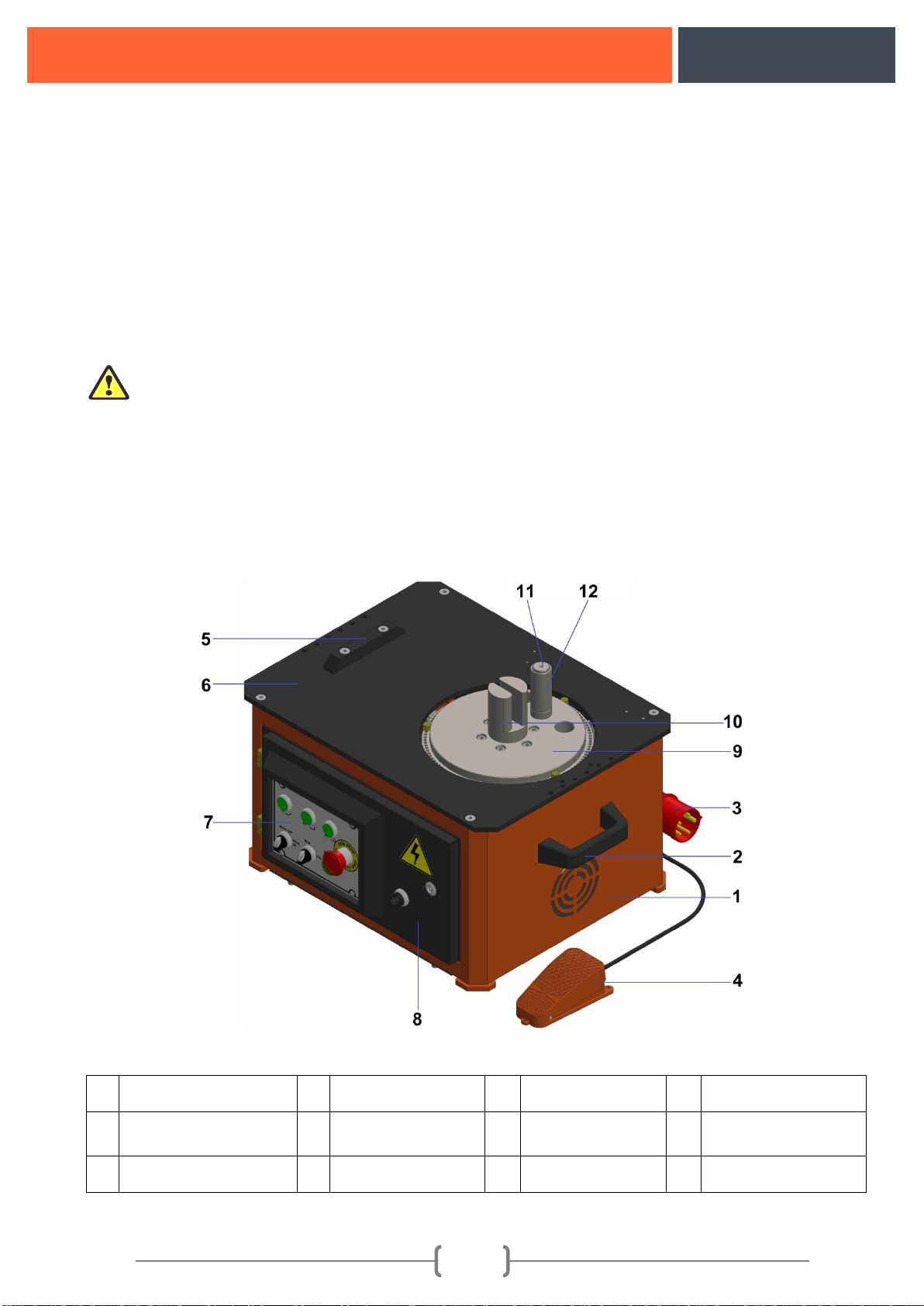
1. MAIN SECTIONS OF REBAR BENDING MACHINE.....................................................................4
2. MACHINE ASSEMBLY......................................................................................................................5
3. MACHINE RUNNING PROCEDURES ORDER...............................................................................6
3.1. Energise and Rotation Determining the Direction of Rotation..............................................................6
3.2. 380V Manual Machine Operation ......................................................................................................7
3.3. 220V Manual Machine Operation ......................................................................................................8
3.4. 380V Digital Machine Operation ........................................................................................................9
3.5. 220VDigital Machine Operation.......................................................................................................10
4. TECHNICAL DATA..........................................................................................................................11
5. EQUIPMENT SUPPLIED WITH MACHINE...................................................................................11
6. OPERATION OF MACHINE............................................................................................................12
6.1. Correct Positioning of Rebar On The Machine............................................................................12
6.2. Incorrect Positioning of Rebar On The Machine .........................................................................12
7. PROHIBITED USAGE ON THE MACHINE ...................................................................................13
8. SCOPE OF WARRANTY..................................................................................................................13
9. PROTECTORS TO BE USED WHEN WORKING WITH THE MACHINE..................................14
9.1. Protector apparel...........................................................................................................................14
9.2. Work clothes.................................................................................................................................14
10. TRANSPORTATION THE MACHINE ..........................................................................................14
11. CONTROLS AND SETTINGS ON THE MACHINE.....................................................................15
11.1. Thermal Settings Diagram And Motor Protective Switch ........................................................16
11.2. Hook Bending setting (P3-45°) .........................................................................................……17
11.3. Set-Square Bending setting (P2-90°): .......................................................................................18
11.4. Bent Bar Bending setting (P1-180°): ........................................................................................18
11.5. Stirrup Bending .........................................................................................................................19
12. MAINTENANCE AND LUBRICATION INSTRUCTIONS..........................................................19
13. TROUBLESHOOTING....................................................................................................................20
14. MACHINE SPARE PARTS LIST....................................................................................................21

MG 20 B
GÖÇMAKSAN
2
15. MACHINE ASSEMBLY..................................................................................................................22
16. GEARBOX SPARE PARTS LIST...................................................................................................23
17. ELECTRICAL PANEL PARTS LIST .............................................................................................24
17.1. 220V Digital Machine Eelectrical Panel Parts List....................................................................24
17.2. 220V Manual Machine Eelectrical Panel Parts List...................................................................24
17.3. 380V Digital Machine Eelectrical Panel Parts List....................................................................25
17.4. 380V Manual Machine Eelectrical Panel Parts List...................................................................25
18. MACHINE ELECTRICITY SCHEME............................................................................................26
19. ABOUT US.......................................................................................................................................27
LIST OF FIGURES
Figure 1: Main sections of bending machine............................................................................................4
Figure 2: Leveling the machine on a solid ground....................................................................................5
Figure 3: DeterMining the Direction of Rotation .....................................................................................7
Figure 4: 380V Manual Control Buttons ..................................................................................................7
Figure 5: 220V Manual Control Buttons ..................................................................................................8
Figure 6: 380V Digital Control Buttons ...................................................................................................9
Figure 7: 220V Digital Control Buttons..................................................................................................10
Figure 8: Machine Table Retaining the Ruler.........................................................................................11
Figure 9: Correct Positioning of Rebar On The Machine.......................................................................12
Figure 10: Incorrect Positioning of Rebar On The Machine ..................................................................12
Figure 11: Transporttaion of the machine...............................................................................................15
Figure 12: Control Panel And Functions ................................................................................................15
Figure 13: Motor Protective Switch........................................................................................................16
Figure 14: Hook Bending (P3)................................................................................................................17
Figure 15: Bend-Up Bending (P2)..........................................................................................................17
Figure 16: Set-Square Bending (P1).......................................................................................................17
Figure 17: Stirrup Bending ....................................................................................................................18
Figure 18: Maintenance and Lubrication of the Machine.................Hata! Yer işareti tanımlanmamış.

MG 20 B
GÖÇMAKSAN
3
MAIN SECURITY INFORMATION
This symbol is put before the articles giving warning explanations in order to draw attention of the
trained operator to important functions.
€This symbol is put before the articles giving warning explanations in order to draw attention of the
trained operator to electrical issues.
This symbol is put before the sentences in order to draw attention of the trained operator to the
master instructions and directive regarding to handling or safety.
STICKERS USED ON THE MACHINE
Manufacturer’s Brand Cliche
Manufacturer’s Logo Cliche
MG 20 B
Machine’s Model Name Sticker
CE norm conformity sticker
Plate of capacity and technical information of the machine
Machine user's and maintanance manual sticker
Kaldırma ve taşıma kancası yeri etiketi
Electricity panel warning sticker
Grounding output sticker

MG 20 B
GÖÇMAKSAN
4
INTRODUCTION
MG20B Portable Rebar bending machine is only intended for bending the rebar. The utilization of it for all
purposes is prohibited, except this purpose.
In order to operate your machine better, the machine should be placed so as to be operated easily and in the
position which allows operator to work more productively. For this reason, the place, where the machine is
operated, should be close to the area where the rebar is kept. In addition to it, it will be useful that the roof of the
place, where the machine operates, is covered with shed. We recommend you to place the workbenches in the
both sides of machine. The length of those workbenches should be at the longest length of rebar which will be
bent. Since the operator may work easily by those benches without rotation, lifting all rebar, it shall allow
operator to work more productively.
Important Warnings !!!
The maintenance and user’s manuals should certainly be read.
Just the persons, who are adequately informed on it, should work with the machine.
While the machine is checked, maintained, lubricated, etc., the power of the machine should be cut off.
All instructions in the maintenance and user’s manual should be observed.
1. MAIN SECTIONS OF REBAR BENDING MACHINE
Figure 1: Main Sections Of Rebar bending Machine
1
Machine Chasis
4
Foot Pedal
7
Control Panel
10
Stirrup Head
2
Holding Handle
5
Rebar Sliding
Lama
8
Electric Panel
11
Straight Pin
3
Energy Plug
6
Upper Table
9
Bending Disc
12
Bending Sleeve

MG 20 B
GÖÇMAKSAN
5
2. MACHINE ASSEMBLY
Machine should be leveled on a solid ground.Figure 2
Electricity connection of the machine should be made by competent technicians
Electricity Connection
For main electricity connection plug should be connected to supply line with a 5x2,5 mm²
isolated cable and then plugged into power outlet. ( maximum 25 mt. )
Grounding connection should be made for safety. Machine shouldn't be operated without
making grounding connection.
Connection of grounding line
The following procedures should be followed for this system
Connect one end of the grounding to a copper wire (minimum 16 mm²) as it will enable electrical
conductivity. The other end should be either connected with a pipe that has a conductivity capacity
immerged into the ground (preferably into a humid ground) or the copper plate should be burried into
the ground as much as deep.
Figure 2: Leveling the machine on a solid ground

MG 20 B
GÖÇMAKSAN
6
3. MACHINE RUNNING PROCEDURES ORDER
3.1. Energise and Rotation Determining of the Direction of Rotation
Ensure that the machine is settled up properly according to assemblying rules.
Empty the bending Tools on the machine before starting to bend.
Start the machine by Plugging it to the energy (Figure:1 No:3) and open the electric panel cover
(Figure:1 No:8) and switch the main switch (Figure:3 No:14) from “0” to “1” . on digital models,
switch “ON-OFF” button to “ON” position on the control panel.
Ensure that the power lamp on manual models and control pabel lamps on the digital models are
lighting after the machine is started.
Determine the direction of the rotation by switching the MAN-AUTO button to MAN position on
the control panel and by pressing the foot pedal. (Figure:1 No:4)
Take the front side of the machine as Reference, and the clockwise rotation of bending disc on
Figure:1 No:9 should be right and counter clockwise rotation should be left. Manufacturer
recommends the right side bending. If the bending disc is turning to left side, the phases coming
from the main electric network should be reverse. This situation does not affect the working system
of the machine. In case of facing the same, if the machine is a digital model, change the LEFT-
RIGHT posisition from the control panel or if it is manual model, change the direction of phases by
an experienced electrician.
Start to the bending adjustments after determining the direction of rotation.
Figure 3: Determining the Direction of Rotation
13
Switch Pin
14
Main Switch
3.2. Operation of 380V Manual Machine:

MG 20 B
GÖÇMAKSAN
7
Place the suitable stirrup head for your rebar, the straight pin and the bending sleeve (Figure:1
No:10,11,12) to the related holes of the bending dics.
Locate the switch pins on the small holes around the bending disc to adjust the bending angle .
(Figure:3 No:13)
Select the bending shape from the buttons on the control panel. (Figure:4 No:16,17,18)
On stirrup bendings, switch the PROG. ON-OFF button to (Figure4: No:19) “ON” position and
max. 9 different bending is adjusted at once and the bending can be done in the adjusted order.
After the adjustment is finished, switch the MAN-AUTO button(Figure:4 No:20) to AUTO
poisition and start to serial bending.
In case of an emergency, machine can be stopped by pressing the ‘emergency stop button2 on
thecontrol panel. (Figure:4 No:22) When you start to bend machine will re-start from the latest
adjusted programme.
Figure 4: 380V Manual Machine Control Buttons
15
Control Panel
17
P2 Button
19
Prog.On-Off
21
Power Lamp
16
P1 Button
18
P3 Button
20
Man-Auto Button
22
Emergency Stop
3.3. Operation of 220V Manual Machine:

MG 20 B
GÖÇMAKSAN
8
Place the suitable stirrup head for your rebar, the straight pin and the bending sleeve (Figure:1
No:10,11,12) to the related holes of the bending dics.
Locate the switch pins on the small holes around the bending disc to adjust the bending angle .
(Figure:3 No:13)
Select the bending shape from the buttons on the control panel. (Figure:5 No:24,25,26)
Adjust the machine’s speed by the Speed Controller (Figure:5 No:31) Once the speed of the
machine decreased, the bending disc’s rotation speed will reduce and machine’s power (bending
capacity) will increase. And when the speed is increased the bending disc’s rotation speed will
increase and the machine’s power ( bending capacity ) will decrease.
As soon as the speed decreases the bending capacity will increase, and the speed increases the
bending capacity decreases.
On stirrup bendings, switch the PROG. ON-OFF button to (Figure5: No:27) “ON” position and
max. 9 different bending is adjusted at once and the bending can be done in the adjusted order.
After the adjustment is finished, switch the MAN-AUTO button(Figure:5 No:28) to AUTO
poisition and start to serial bending.
In case of an emergency, machine can be stopped by pressing the ‘emergency stop button2 on
thecontrol panel. (Figure:5 No:30) When you start to bend machine will re-start from the latest
adjusted programme.
Figure 5: 220V Manual Machine Control Buttons
23
Control Panel
26
P3 Button
29
Power Lamp
24
P1 Button
27
Prog.On-Off Button
30
Emergency Stop
25
P2 Button
28
Man-Auto Button
31
Speed Controller

MG 20 B
GÖÇMAKSAN
9
3.4.Operation of 380V Digital Machine:
Place the suitable stirrup head for your rebar, the straight pin and the bending sleeve (Figure:1
No:10,11,12) to the related holes of the bending dics.
Press to SET button on the control panel and than to PROG button and enter the intended data. Use
the UP and DOWN arrows (Figure:6 No:39) and enter the intended angle degree to the angle
indicator. (Figure:6 No:37) Press the right arrow and switch to unit indicator (Figure:6 No:38) and
enter the intended unit. Once angle and unit data is entered press to down arrow and switch to SET
line. Enter the data to set line and save it by pressing to PROG button. Maximum 9 value can be
entered for each set line indicator.
After the adjustment is finished switch to MAN-AUTO button (Figure:6 No:34) to AUTO position
and start to serial bending.
After the bending finishes due to various steel quality entered data and bended angle should differ,
in case of such situations press to UP arrow for 15 seconds period. “100” or machine’s factory
settting “35” will appear on SET3 line’s angle indicator. Use UP and DOWN arrows and change
the angle as much as the bended angle difference and renew the calibration process by pressing the
PROG button.
In case of an emergency, machine can be stopped by pressing the ‘emergency stop button2 on
thecontrol panel. (Figure:5 No:30) When you start to bend machine will re-start from the latest
adjusted programme.
Figure 6: 380V Digital Machine Control Buttons
32
Control Panel
36
Set 1,2,3 Button
40
Prog. Button
33
Left-Right B Button
37
Angle Indicator
41
Emergency Stop
34
Man-Auto Button
38
Unit Indicator

MG 20 B
GÖÇMAKSAN
10
35
On-Off Button
39
Value Direction Arrows
3.5. Operation of 220V Digital Machine:
Place the suitable stirrup head for your rebar, the straight pin and the bending sleeve (Figure:1
No:10,11,12) to the related holes of the bending dics.
Press to SET button on the control panel and than to PROG button and enter the intended data. Use
the UP and DOWN arrows (Figure:7 No:49) and enter the intended angle degree to the angle
indicator. (Figure:7 No:47) Press the right arrow and switch to unit indicator (Figure:7 No:48) and
enter the intended unit. Once angle and unit data is entered press to down arrow and switch to SET
line. Enter the data to set line and save it by pressing to PROG button. Maximum 9 value can be
entered for each set line indicator.
Adjust the machine’s speed by the Speed Controller (Figure:7 No:52) Once the speed of the
machine decreased, the bending disc’s rotation speed will reduce and machine’s power (bending
capacity ) will increase. And when the speed is increased the bending disc’s rotation speed will
increase and the machine’s power ( bending capacity ) will decrease.
As soon as the speed decreases the bending capacity will increase, and the speed increases the
bending capacity decreases.
After the adjustment is finished, switch the MAN-AUTO button(Figure:7 No:44) to AUTO
poisition and start to serial bending.
After the bending finishes due to various steel quality entered data and bended angle should differ,
in case of such situations press to UP arrow for 15 seconds period. “100” or machine’s factory
settting “35” will appear on SET3 line’s angle indicator. Use UP and DOWN arrows and change
the angle as much as the bended angle difference and renew the calibration process by pressing the
PROG button.
In case of an emergency, machine can be stopped by pressing the ‘emergency stop button2 on
thecontrol panel. (Figure:7 No:51) When you start to bend machine will re-start from the latest
adjusted programme.
Figure 7: 220V Digital Machine Control Button

MG 20 B
GÖÇMAKSAN
11
42
Control Panel
46
Set 1,2,3 Button
50
Prog. Button
43
Left-Right Button
47
Angle Indicator
51
Emergency Stop
44
Man-Auto Button
48
Unit Indicator
52
Speed Controller
45
On-Off Button
49
Value Direction Arrows
4.TECHNICAL DATA
Machine Model : MG 20 B
Machine Name : Portabel Stirrup Bending Machine
4.1. Machine Bending Capacity:
4.2. Machine Dimensions :
Width : 48 cm
Lenght : 60 cm
Height : 32 cm
Machine Weight : 76 kgs
Total Weight : 87 kgs (including all bending Tools)
Machine weight vary due to being 220V or 380V and manual or Digital max. ±2 kgs. The given
weight is the approximate weight.
4.3. Machine Table Dimensions:
Width : 43 cm
Lenght : 51 cm
Height : 51 cm
Weight : 6 kgs
4.4. Motor Specifications:
Motor Power : 1,5 kw
Motor Rotation : 1450 rpm
Motor Voltage : 380/220 V
Motor Frequency : 50 Hz
Makine Speed : 0,5-15,1 rpm
5. EQUIPMENT SUPPLIED WITH MACHINE
Straight Pin : 1 ea
Stirrup Head : 4 ea
Bending Sleeve : 2 ea
Switch Pin : 3 ea
Machine Table : 1 ea (optional)
Ruler : 1 ea (optional)
Steel Quality
Diameter / Bendable Unit
45 kg/mm²
Ø 20x1 Ø 14x2 Ø 12x3 Ø 10x4
65 kg/mm²
Ø 16x1 Ø 12x2 Ø 10x3 Ø 8x4
85 kg/mm²
Ø 14x1 Ø 10x2 Ø 8x3 Ø 6x5

MG 20 B
GÖÇMAKSAN
12
Figure 8: Machine Table and Ruler
6. OPERATION OF MACHINE
6.1. Correct Positioning of Rebar On The Machine
Correct Positioning of the rebar onto the
machine by the help of bending Tools on
single bending.
Correct Positioning of the rebar onto the machine
by the help of bending Tools on multiple
bending.
Figure 9: Correct Positioning of Rebar On The Machine
6.2. Incorrect Positioning of Rebar On The Machine
Incorrect Positioning of rebar onto the machine
without using the bending sleeve
Incorrect Positioning of rebar onto the machine
by mis-use of stirrup head.

MG 20 B
GÖÇMAKSAN
13
Incorrect Fixing of the rebar onto the machine
accroding to the rotation of the bending disc.
Incorrect Fixing of the rebar onto the machine
accroding to the rotation of the bending disc.
Figure 10: Incorrect Positioning of Rebar On The Machine
7. PROHIBITED USAGE ON THE MACHINE
Machine mustn't be run when it is wet.
No any bending must be made other than the measurements, dimensions and units stated on
the capacity plate.
Machine mustn't be run when the electricity Panel Cover.
Electrical settings made in the factory shouldn't be changed.
Machine shouldn't be operated without making grounding connection.
Machine shouldn't be operated when any of its parts is dismantled.
Machine should be operated by instructed operators.
Machine never should be run unlubricated.
Warning plates attached on the machine mustn't be removed
No other parts should be mounted to the machine other than the ones manufactured by
Gocmaksan.
No bending should be made on the machine with bending apparatus which are deformed,
cracked or have an increased hole diameter.
No wrong bending should be made on the machine. (Figure:10)
The rebar to be bent has to be placed correctly by the help of bending Tools (Figure:9)
Machine should be cleaned by air.
Main Electricity should be cut-off when machines electrical panel has to be open.
When bending no one must stand in front of the machine and any one standing must be taken
away.
While the machine is running no any other construction material such as adze, hammer, meter,
caliper etc. should be put between the bending apparatus other than the material that will be
bent.
During the multi bending number of Rebars stated on the capacity plate should be aligned one
on top of the other and should be leaned to the retainer or bending rollers. No any other
bending should be made other than this.
8. SCOPE OF WARRANTY
Manufacturer acknowledges warranty and liability provided that complying with the following
conditions.
Protectors found on the machine should be used.
Warning signs should be taken into account.

MG 20 B
GÖÇMAKSAN
14
Machine shouldn't be operated without making grounding connection.
Parts manufactured by GMS company should be used in case it is required to replace a broken
part.
Conditions indicated under the safety measures should be taken into account.
Prohibited usage should be taken into account.
Machine should be assembled in conformance with the assembly conditions.
Machine should be transported in conformance with the handling conditions.
Machine should be used by informed and authorized person.
Measurements, dimensions and steel quality stated on the capacity plate should be taken into
account.
Machine should be used in conformance with its manufacturing purpose.
Electricity connection should be made by competent technicians.
Machine shouldn't be used with any of the parts on it disassembled.
Motor of the machine shouldn't be changed.
Maintenance of the machine should be made in conformance with the maintenance conditions.
No Rebar higher than the indicated size should be bent with retainer (maximum 16 mm)
Correct bending should be made with the machine. (Figure:9)
9. PROTECTORS TO BE USED WHEN WORKING WITH THE MACHINE
9.1. Protector apparel
Helmet must be worn.
Glasses must be worn.
Boots with steel toe must be put on.
Gloves must be worn.
The aforementioned protectors will be used. In case of not using these apparels there are risks of
injury, cutting and trapping hands.
9.2. Work clothes
Inappropriate clothes against snatch or grip while working with the machine are listed below and
in case of not conforming with this list might cause risk of injury.
Long hair, dress with long arms, bracelet, uniform with long skirt, any ornament leaning out.
10.TRANSPORTATION OF THE MACHINE
It is possible to carry the machine by manpower. Forklift has to be used only when the machine in
a crate. In order to carry the machine in a crate machine’s bottom shouldn’t touch on the bottom of the
crate, it is recommended to put skids between the machine and the crate. During the lifting operations
experienced expert staff and subcontractors should be assigned.
WARNING !!!
Machine should be moved without any vibration. Machine shouldn't be run in a wet environment.
If there are any lost or damaged parts during the handling, they should be reported to the manufacturer.
When using the lifting and carrying equipments their maximum loading capacities should be taken
into consideration.
During the lifting equipment's center of gravity should be taken into consideration.
WARNING!!! Warning signs on the carrier equipment should be taken into consideration.

MG 20 B
GÖÇMAKSAN
15
Figure 11: Transportation of the Machine
11. CHECKS AND ADJUSTMENTS
Figure 12: Machine Control Panel and Functions
NO
BUTTON
FUNCTION
53
Control Panel
It is such a panel that keeps the control functions / electrical parts on it.
54
P1
Adjustment for bent bar bending.
55
P2
Adjustment for set-square bending
56
P3
Adjustment for hook bending
57
Prog. On - Off
Adjusts the stirrup mode on-off.
58
Man - Auto
Provides the manual and automatic control of machine.
59
Power
When ON button is pressed and power comes into the system, it lights on
and shows that there is electricity in the system
60
Emergency Stop
Stops the machine by cutting the power off in case of emergency

MG 20 B
GÖÇMAKSAN
16
11.1 Thermal current adjustment field setting and engine protection switch:
The machine is adjusted by its manufacturer as 1,5 kW 1450 rpm 10,2 A for engine. It is not allowed
user to readjust it. The motor protective switch is placed in the machine in order to avoid damaging the
system by cutting the power off which comes into the system, when the excessive current comes into
the system. In case that the switch is off, the switch is turned into the 1 position and is on. Otherwise,
the engine protection switch should not be removed. (Figure:13)
Figure 13: Motor Protection Switch
11.2. Hook Bending (P3)
Machine’s turning direction is to be checked on MAN Mode. There are three SWITCH pins on the
bending disc at the same length on Manual Bending Models. In order to make the hook bending on the
machine, the correct bending angle should be adjusted proper for the hook bending by moving the
SWITCH pin on the angle adjustment holes around the bending disc. (As much as SWITCH pin closes
toward SWITCH, the bending angle reduces, as much as it moves away from SWITCH, the bending
angle increases).
One should press the P3 button on the control panel.
61
Speed Controller
Adjusts the machine’s speed.
62
SET 1-2-3
The lines where the bending data is entered. Has same functions with
P1,P2,P3 Buttons.
63
Angle Line
Bending angle is adjusted in this line.
64
Unit Line
Bending unit is adjusted in this line.
65
Function Arrows
Ensures shifting between the functions and entering the numerical data.
66
Left - Right
Ensures the machine to rotate to the right or left direction
67
On - Off
Ensures the machine to be started or stopped
68
Foot Pedal
Enables the bending disc to rotate.

MG 20 B
GÖÇMAKSAN
17
On digital models, enter 180” pieces line “1” data to the angle indicator on SET1 line and press PROG
button.After the adjustment procedure is completed, the stirrup head is inserted into the axles hub
where is located on bending disc middle. Locate straight pin into one of the holes on the bending disc
so as providing the suitable space due to the thickness of the rebar to be bent and place the one of
proper bending bushes onto the pin. Then place the bending sleeves which is proper for the diameter of
rebar to be bent onto the pin. Put one of other pins into one of the holes on the bending disc so as
providing the suitable space due to the thickness of the rebar to be bent and place the one of proper
bending bushes onto the pin. Place the rebar which you will bend onto the machine. Finally, in order to
avoid injury possibly caused by moving of rebar after bending disc turns it back and the rebar returns,
rebar should be located into the suitable stirrup head ( channeled pin ) because of safety conditions. it
should be placed in front of the rebar and onto the bending bracket for security (FIGURE:9-14).
Switch the machine to AUTO mode for serial bendings.
NOTE: When the machine is in the MAN position, as long as the foot pedal is pressed, the bending
disc turns, and it stops, as the bending procedure is completed and the machine comes to the stand-by
position. When the machine is in the AUTO position, the bending disc bends by pressing the foot
pedal once and stops, when the machine comes to the stand-by position. In addition, when the machine
is in the AUTO position again, the bending disc may stop as the foot pedal is pressed during the
bending process. When the bending disc stops in such manner, it stops in the zero point in contrary to
the bending direction by pressing the foot pedal continuously.
In order to change the adjustment, press the P1-P2-P3 buttons and in case of changing the adjustment,
wait until the machine completes the bending process and stops, and press to the desired button in
order to change the adjustment. Otherwise, when the buttons are pressed in order to change the
adjustment, the adjustment change shall not be affective.
Figure 14: Hook Bending Setting
11.3. Set-Square Bending : (P2)
By pressing to the P2 button on the control panel, the adjustment should be made same as the
adjustment method of hook bending.

MG 20 B
GÖÇMAKSAN
18
Figure 15: Set-Square Bending
11.4. Bent-Bar Bending (P1)
By pressing to the P1 button on the control panel, the adjustment should be made same as the
adjustment method of hook bending
Figure 16: Bent-Bar Bending
11.5. Stirrup Bending:
On Manual models, presss hook bending button ( P3) on the control panel and the first adjustment
should be made for the end bending of the rebar which will be stirrup by the adjustment unit in the
hook section so as the bending angle shall be 135º. And then, the press setsquare bending position (P2)
and the second bending adjustment should be made so as the bending angle shall be 90º. Later on,
switch the PROG ON-OFF button to ON Position and in return, press once to P3, 3 times to P2 and
again once to P3 button. In digital models, enter 1 to 135 cell of SET1 line, enter 3 to 90 cell of SET2,
enter 1 to 135 cell of SET3 angle indicator. And press PROG button. After the adjustment procedures
are completed (FIGURE: 17) , the bending order should be followed and stirrup bending procedures
should be completed serially on AUTO mode.

MG 20 B
GÖÇMAKSAN
19
Figure 17: Stirrup Bending Adjustment
12. MAINTENANCE AND LUBRICATION INSTRUCTIONS
It is important to make maintenance correctly in order to extend service life of the machine and to
ensure safe bending. We suggest for each user to set up a secure system for control and maintenance of
the machine. The following descriptions are given for reference. Number 140 and 90 gear oil is used in
machine's gearbox.
(17a)
(17b)
(17d)
(17c)
(17f)
(17e)
Table of contents
Other GOCMAKSAN Construction Equipment manuals