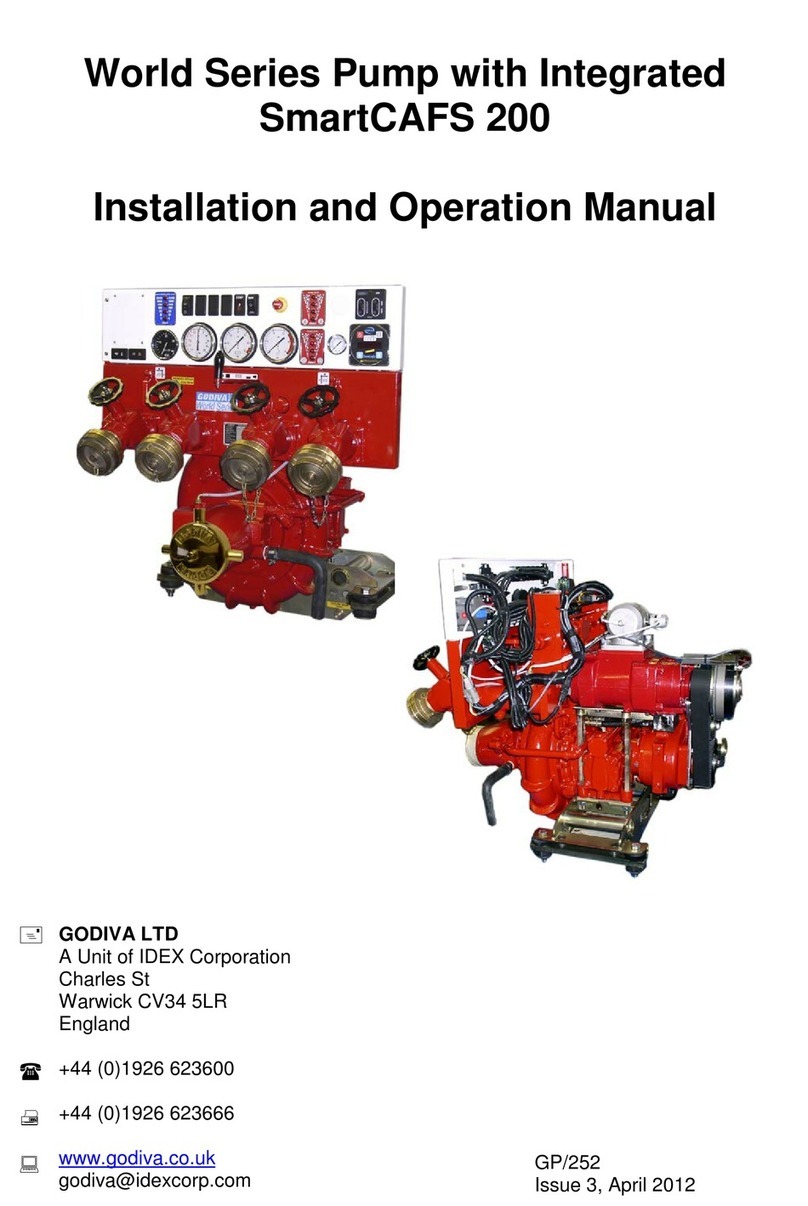
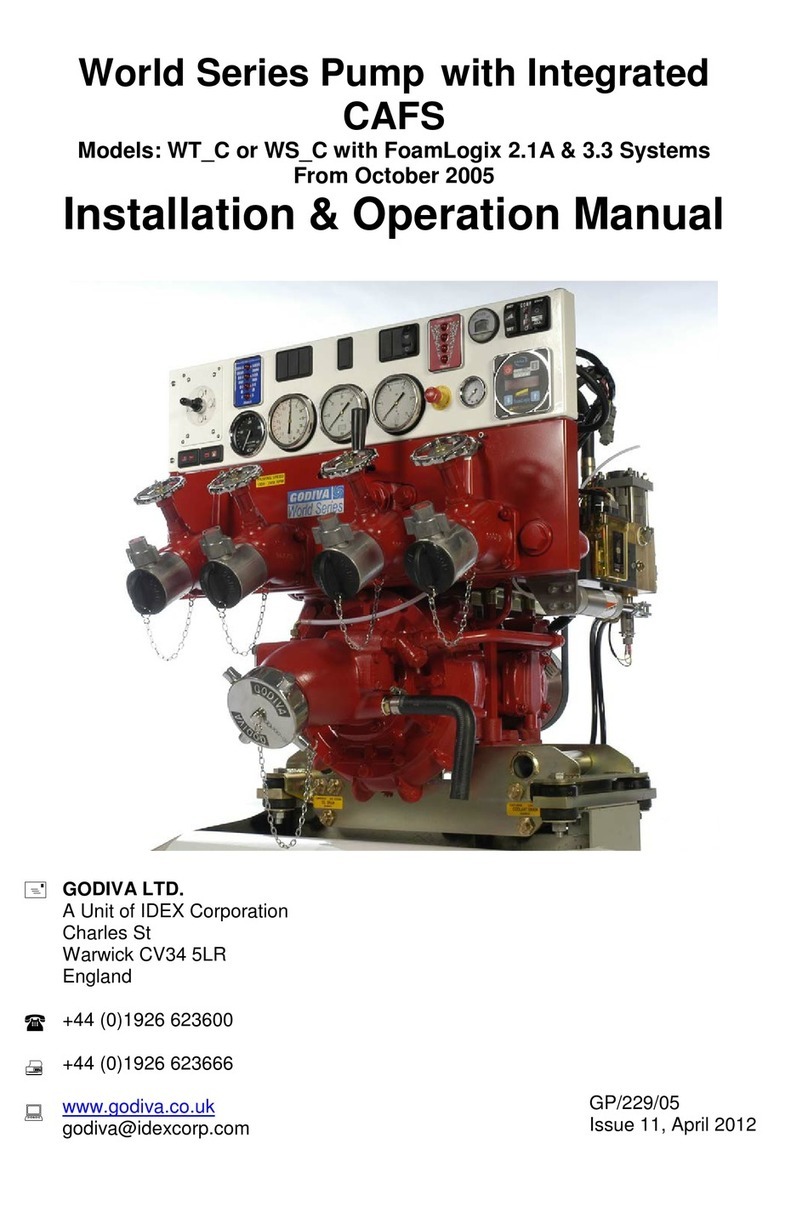
Godiva Prima PC1 User manual

Prima
Pump with Integrated
Models: PC1_ or PC2_ with SmartCAFS50 or SmartCAFS100 Control
with FoamLogix 2.1A, 3.3 or 5.0 Systems
Installation and Operation Manual
Godiva Ltd.
A Unit of IDEX Corporation
Charles St
Warwick CV34 5LR
England
+44 (0)1926 623600
+44 (0)1926 623666 / 623689
www.godiva.co.uk
GP/293
Issue 5, February 2014

2
©Godiva Ltd. Our policy is one of continuous development. We therefore reserve the
right to amend specifications without notice or obligation.
AMENDMENT RECORD
Model: PC1_ or PC2_ with SmartCAFS50/100 Control and FoamLogix 2.1A, 3.3, 5.0 Systems
Mod
Date
Page/s
Amendment
New Issue
No.
1
September
2011
All
New Issue
Issue 1,
2
April 2012
11, 25-26
Gearbox oil capacity –now 1.2 litres
Issue 2.
3
April 2012
42
CAFS mixing manifold –greasing ball valve
Issue 3
4
September
2012
8, 38
Information on clutch sparking, normal condition
Issue 4
5
Feb 2014
16
Items 11,12,13, can be located on top row
Issue 5
6
Feb 2014
14
Add details on new Interlock for compressor clutch
control
Issue 6
7
Feb 2014
9, 34
Insert minimum pump idle speed information
Issue 6

3
©Godiva Ltd. Our policy is one of continuous development. We therefore reserve the
right to amend specifications without notice or obligation.
CONTENTS
AMENDMENT RECORD.................................................................................................2
CONTENTS.....................................................................................................................3
INTRODUCTION.............................................................................................................6
IMPORTANT NOTES......................................................................................................6
MODEL IDENTIFICATION SYSTEM......................................................................................6
SAFETY ..........................................................................................................................7
IN OPERATION ................................................................................................................7
TRAINING.......................................................................................................................7
MAINTENANCE................................................................................................................7
RISK ASSESSMENT.........................................................................................................7
TRANSPORTATION AND STORAGE ....................................................................................7
GAUGES ........................................................................................................................8
CLUTCH ENGAGEMENT ...................................................................................................8
ENVIRONMENTAL PROTECTION.................................................................................8
GENERAL DATA............................................................................................................9
COMPRESSOR –50SCFM RATING.....................................................................................9
COMPRESSOR –100SCFM RATING...................................................................................9
PRIMA SMARTCAFS/FOAMLOGIX SYSTEM/COMPRESSOR –COMPATIBILITY CHART ............9
FOAM PROPORTIONING SYSTEM 2.1A -CLASS AFOAM COMPATIBLE ...............................10
FOAM PROPORTIONING SYSTEM 3.3 -CLASS AAND BFOAM COMPATIBLE........................10
FOAM PROPORTIONING SYSTEM 5.0 -CLASS AAND BFOAM COMPATIBLE........................10
DIRECTION OF ROTATION -GEARBOX INPUT FLANGE.......................................................10
LUBRICANTS ...............................................................................................................11
COMPRESSOR –TEMPEST 3..........................................................................................11
COMPRESSOR –TEMPEST 6..........................................................................................11
PUMP GEARBOX...........................................................................................................11
PUMP BEARING HOUSING..............................................................................................11
RECOMMENDED FOAM AGENTS ..............................................................................11
MAJOR COMPONENTS AND CONTROLS PRIMA SMARTCAFS50 SYSTEM (USING
TEMPEST 3 COMPRESSOR).......................................................................................12
MAJOR COMPONENTS AND CONTROLS PRIMA SMARTCAFS100 SYSTEM
(USING TEMPEST 6 COMPRESSOR).........................................................................12
INTERLOCK FOR COMPRESSOR CLUTCH CONTROL –PRIMA SMARTCAFS50 AND 100
MODELS ......................................................................................................................14
FOAMLOGIX 2.1A FOAM PUMP COMPONENT GROUP.......................................................15
FOAMLOGIX 3.3 OR 5.0 FOAM PUMP COMPONENT GROUP ..............................................16
SHOWING PARTS SUPPLIED LOOSE WITH STANDARD PUMP................................................16
SYSTEM OVERVIEW ...................................................................................................18
COMPRESSOR..............................................................................................................18
MANIFOLD....................................................................................................................19
FOAMLOGIX -FOAM PROPORTIONING SYSTEM................................................................19

4
©Godiva Ltd. Our policy is one of continuous development. We therefore reserve the
right to amend specifications without notice or obligation.
INSTALLATION AND INITIAL SET-UP PRIMA SMARTCAFS50 USING TEMPEST 3
COMPRESSOR AND FOAMLOGIX 2.1A PRIMASMARTCAFS100 USING TEMPEST
6 COMPRESSOR AND FOAMLOGIX 3.3 OR 5.0........................................................20
LIFTING POINTS –PRIMA SMARTCAFS50 AND PRIMA SMARTCAFS100 ..........................20
PRIMA SMARTCAFS50 SYSTEM....................................................................................21
FOAMLOGIX 2.1A SYSTEM –REMOTE MOUNTED ............................................................21
PRIMA SMARTCAFS100 SYSTEM..................................................................................22
FOAMLOGIX 3.3 OR 5.0 SYSTEM –REMOTE MOUNTED (3.3 MODEL SHOWN).....................22
OIL FILLING POINTS –PRIMA SMARTCAF50...................................................................24
OIL FILLING POINTS –PRIMA SMARTCAF100.................................................................25
GEARBOX –PRIMA SMARTCAFS50 AND PRIMA SMARTCAF100 .....................................26
GEARBOX IN DOWN POSITION........................................................................................26
GEARBOX IN HORIZONTAL POSITION,LEFT OR RIGHT OF PUMP ........................................26
FOAM INJECTION POINT ................................................................................................27
OPTICAL BELT TENSION METER.....................................................................................28
COMPRESSOR DRIVE BELT –PRIMA SMARTCAFS100....................................................29
OPTICAL BELT TENSION METER.....................................................................................29
ELECTRICAL CONNECTIONS...........................................................................................29
FOAM TANK LOW LEVEL SENSOR...................................................................................31
ADDITIONAL INSTALLATION POINTS ................................................................................31
VEHICLE DESIGN CONSIDERATIONS.......................................................................32
INSTALLATION AND INITIAL SET-UP FOAMLOGIX 2.1A.........................................33
INSTALLATION AND INITIAL SET-UP FOAMLOGIX 3.3, 5.0 ....................................33
OPERATION.................................................................................................................34
FOAMLOGIX CONTROL PANEL FUNCTIONS......................................................................34
COMMISSIONING /START-UP PROCEDURE .....................................................................34
CALIBRATION OF FOAMLOGIX ........................................................................................35
SMART SWITCH OPERATION...........................................................................................35
WET AND DRY BUTTONS..............................................................................................36
WET AND DRY LEDS..................................................................................................36
CONFIGURE THE WET AND DRY PRESETS .....................................................................36
CONFIGURE THE WET PRESET......................................................................................36
CONFIGURE THE DRY PRESET ......................................................................................36
OPEN AND CLOSE BUTTONS.......................................................................................36
OPEN AND CLOSE LEDS...........................................................................................37
VALVE POSITION BARGRAPH INDICATOR (LEDS)..............................................................37
NOTE:TURNING OFF THE FOAMLOGIX OR DISENGAGING THE COMPRESSOR WILL SEND THE
AIR RATIO CONTROL VALVE TO THE EXTREME WET POSITION..........................................37
OPERATING THE PC2_ OR PC1_ FROM A VEHICLE WATER SOURCE................................37
FOAMLOGIX CONTROL PANEL .......................................................................................38
ENGAGING PTO &PRIMING MAIN PUMP ........................................................................38
TANK SELECTION FOAMLOGIX 3.3, 5.0 ONLY..................................................................38
DISCHARGING FOAM /WATER SOLUTION ONLY...............................................................39
DISCHARGING CAFS....................................................................................................39
OVERHEAT SHUT DOWN................................................................................................40
FLUSHING FOAMLOGIX 3.3 OR 5.0 ONLY.........................................................................40
MAINTENANCE SCHEDULE PC2_/PC1_....................................................................41

5
©Godiva Ltd. Our policy is one of continuous development. We therefore reserve the
right to amend specifications without notice or obligation.
MAINTENANCE OPERATIONS PC2 ...........................................................................42
STRAINER -HIGH PRESSURE.........................................................................................42
MAINTENANCE OPERATIONS PC1_ / PC2_..............................................................43
CAFS MIXING MANIFOLD –GREASING BALL VALVE ........................................................43
MAINTENANCE OPERATIONS PC1_ / PC2_ - CONTINUED.....................................44
VACUUM TEST..............................................................................................................44
PRESSURE TEST –CARRIED OUT WITHOUT PUMP RUNNING. .............................................44
THERMAL RELIEF VALVE (TRV) TEST............................................................................44
MAINTENANCE OPERATIONS COMPRESSOR.........................................................45
COMPRESSOR OIL LEVEL CHECK -OIL /FILTER CHANGE.................................................45
COMPRESSOR AIR FILTER.............................................................................................45
COMPRESSOR OIL SEPARATOR ELEMENT.......................................................................45
COMPRESSOR DRIVE BELT............................................................................................45
MAINTENANCE OPERATIONS FOAMLOGIX.............................................................45
STRAINER -FOAM.........................................................................................................45
CALIBRATION ...............................................................................................................45
FAULT FINDING...........................................................................................................46
PUMP OPERATING FAULTS 1–LOSS OF SUCTION..............................................46
PUMP OPERATING FAULTS 2–EXCESSIVE PUMP NOISE...................................47
GENERAL OPERATING FAULTS -CAFS.................................................................48
AIR INJECTION FAULTS ..........................................................................................49
PARTS LISTS...............................................................................................................51
RECOMMENDED SPARES KIT FOR BI-ANNUAL SERVICE.....................................52
INSTALLATION DRAWINGS –PC2_ WITH SMARTCAFS50 FOR OPTIONS OF
DRIVE FLANGE, VALVES, SUCTION TUBE, CONTROL PANEL –CONTACT
GODIVA ........................................................................................................................53
SHEET 1OF 3(BASED ON PC2_3010)...........................................................................53
SHEET 2OF 3(BASED ON PC2_3010)...........................................................................54
SHEET 3OF 3(BASED ON PC2_3010)...........................................................................55
SHEET 1OF 3(BASED ON PC2_3010)...........................................................................56
SHEET 2OF 3(BASED ON PC2_3010)...........................................................................57
SHEET 3OF 3(BASED ON PC2_3010)...........................................................................58
FOAM CONCENTRATE COMPATIBILITY LIST..........................................................59

6
©Godiva Ltd. Our policy is one of continuous development. We therefore reserve the
right to amend specifications without notice or obligation.
INTRODUCTION
This manual contains information relevant to Godiva single or multi-pressure Prima
Series Pumps, when partnered with Compressed Air Foam Systems (CAFS)
FoamLogix Models 2.1A, 3.3, 5.0 and the SmartCAFS50 or 100 control system.
Distinction between the models regarding Installation, Maintenance, Operation and
Specification is clearly noted with text and illustrations.
For further information on the FoamLogix 2.1A, 3.3, 5.0 Foam Proportioning Systems,
MDTII Manual Dual Tank Selector (for 3.3, 5.0 systems) and Intelli-tank Water/foam
level display unit, please see the separate manuals supplied.
IMPORTANT NOTES
Please read this manual before operating the pump.
CRITICAL: The pump Bearing Housing, Gearbox and Compressor are NOT filled with
oil ex works. Refer to section Installation and Set-up (Oil Filling Points) before operation.
Correct lubrication and maintenance is essential if satisfactory performance is to be
maintained.
Do not run the pump without water in the pump casing.
The terms ‘Left Hand’ (LH) and ‘Right Hand’ (RH) apply when the pump unit is viewed
from the suction tube end; for the purposes of this document, this is regarded as the
front of the assembly.
Model Identification System
Variations of the Godiva Prima pump with CAFS are identified thus:
P C 1 A 2010
!
Compressed air foam
1 = single pressure 2 = twin pressure
A = aluminium B = bronze
Godiva Prima series pump
2010 = 2000 l/min@10 bar. 3010 = 3000 l/min@10 bar
4010 = 4000 l/min@10 bar. Main pump output

7
©Godiva Ltd. Our policy is one of continuous development. We therefore reserve the
right to amend specifications without notice or obligation.
SAFETY
Please read this manual before operating the machinery.
Safety notices -
= non-compliance could affect safety
= in case of damage to pump
= in case of personal hazards
In operation
Rotating parts must be guarded against accidental contact.
Do not insert items into the suction tube when pump is running.
Discharge hoses mustnot be disconnected when the unit is running.
No components must be unfastened when the unit is running.
When installing or removing the pump, suitablelifting equipment must be used.
Isolate the electrical supply when working on the pump
Suitable earprotection must be worn when pump is running –if necessary.
Training
Godiva pumps must only be operated by trained personnel.
Maintenance
The user must maintain the equipment in an operational condition, as per regulation 5 in
the Provision and Use of Work Equipment Regulations 1998.
Risk Assessment
It is the duty of the pump installer to make a method statement and risk assessment of
their operations when installing the pump, please contact Godiva Ltd. if assistance is
required.
Transportation and Storage
The pump is supplied mounted on a wooden pallet and covered with a tri-walled
cardboard box. This protection is suitable for standard methods of freight handling using
forklift trucks. No more than one pump should be stacked on top of another. The tri-
walled cardboard box is not suitable for storage outside, or when open to the elements.
The pump is sprayed internally with a moisture inhibitor when leaving the factory, this
treatment may be required if the pump is in long term storage (6 months or more) before
use. On receipt of the pump a full inspection must be carried out, if any damage has
occurred please contact Godiva Ltd.
IMPORTANT
!
ATTENTION

8
©Godiva Ltd. Our policy is one of continuous development. We therefore reserve the
right to amend specifications without notice or obligation.
Gauges
Do not clean the glass surfaces of the gauges with abrasive or solvent cleaners. These
will cloud the glass surface. Use a mild detergent and water.
Clutch Engagement
When the clutch is first engaged it is possible to observe some sparking occurring
around the clutch assembly. This small amount of sparking is quite normal and nothing
to be concerned about. The lower the engagement speed the less sparking will occur.
ENVIRONMENTAL PROTECTION
It is prohibited to pour engine oil and other contaminants onto the ground, down sewers,
drains, or into water courses.
Dispose of lubricants through authorised waste disposal contractors, licensed waste
disposal sites, or to the waste reclamation trade.
If in doubt, contact your Local Environmental Agency for advice regarding disposal
policies.

9
©Godiva Ltd. Our policy is one of continuous development. We therefore reserve the
right to amend specifications without notice or obligation.
GENERAL DATA
Compressor –50scfm rating
Model Tempest 3
Maximum Operating Speed 10000 rpm
Nominal speed of operation 6250 rpm
Nominal power draw 12 kW
Direction of rotation Anti-clockwise (viewed on pulley)
Volume output 1420 l/min
Oil Capacity 3.5 litres
Oil Capacity with filter change 4.0 litres
Operational pressure range 4 –10 bar
Cooling System
Type Oil/Water Shell & tube type
Cooling water flow-rate 10/15 Litres / Min at 7.0 Bar
Compressor –100scfm rating
Model Tempest 6
Maximum Operating Speed 8000 rpm
Nominal speed of operation 5350 rpm
Nominal power draw 28 kW
Direction of rotation Anti- clockwise (viewed on pulley)
Volume output 2830 l/min
Oil Capacity 4.5 litres
Oil Capacity with filter change 6.0 litres
Operational pressure range 4 –10 bar
Cooling System
Type Oil/Water Shell & tube type
Cooling water flow-rate 20/30 l/min at 7.0 Bar (0.7 MPa)
Pump
Minimum idle speed 900-1000rpm
Prima SmartCAFS/FoamLogix System/Compressor –Compatibility Chart
Pump plus
CAFS
FoamLogix
FoamLogix
FoamLogix
Compressor
Prima
SmartCAFS50
2.1A
3.3
Tamrotor
Tempest 3
Prima
SmartCAFS100
2.1A
3.3
5.0
Tamrotor
Tempest 6

10
©Godiva Ltd. Our policy is one of continuous development. We therefore reserve the
right to amend specifications without notice or obligation.
Foam Proportioning System 2.1A - Class A Foam Compatible
Manufacturer Hale Products Inc
Model FoamLogix 2.1A
Type Electronic foam proportioning system
Operating voltage 12 and 24 volt systems available
Fuse rating 12V / 24V 50 / 40 amp
Current draw (Operating) 12V / 24V 25 / 13 amp
Current draw (Max) 12V / 24V 40/20amp
Wire size 12V / 24V Minimum 6.0mm2
Max. Foam Agent Flow rate 8.0 Litres / Minute
Foam Proportioning System 3.3 - Class A and B Foam Compatible
Manufacturer Hale Products Inc
Model FoamLogix 3.3
Type Electronic foam proportioning system
Operating voltage 12 and 24 volt systems available
Fuse rating 12V / 24V 60 / 40 amp
Current draw (Operating) 12V / 24V 30 / 24 amp
Current draw (Max) 12V / 24V 60/30amp
Wire size 12V / 24V Minimum 8.5mm2
Max. Foam Agent Flow rate 12 Litres / Minute
Foam Proportioning System 5.0 - Class A and B Foam Compatible
Manufacturer Hale Products Inc
Model FoamLogix 5.0
Type Electronic foam proportioning system
Operating voltage 12 and 24 volt systems available
Fuse rating 12V / 24V 70 / 40 amp
Current draw (Operating) 12V / 24V 30 / 15 amp
Current draw (Max) 12V / 24V 60 / 30 amp
Wire size 12V / 24V Minimum 8.5mm2
Max. Foam Agent Flow rate 19 l/min
Direction of Rotation - Gearbox Input Flange
Clockwise only - viewed on gearbox input drive flange

11
©Godiva Ltd. Our policy is one of continuous development. We therefore reserve the
right to amend specifications without notice or obligation.
LUBRICANTS
Compressor –Tempest 3 Recommended: Screw compressor oil in
compliance with ISO Viscosity grade 32 to 46.
Alternative: SAE 10W/40 automotive
multigrade oil.
Capacity 3.5 litres - (approximately 4.0 litres
with filter change)
Compressor –Tempest 6 Recommended: Screw compressor oil in
compliance with ISO Viscosity grade 32 to 46.
Alternative: SAE 10W/40 automotive
multigrade oil.
Capacity 4.5 litres - (approximately 6.0 litres
with filter change)
Pump Gearbox Capacity 1.2 litres approximately
Recommended: BP Energol GR XP 68 or
similar
Pump Bearing Housing Capacity 1.0 litres approximately.
Recommended: 10W/40 or 15W/40 Multi-
grade engine oil.
RECOMMENDED FOAM AGENTS
Hale FoamLogix Models 2.1A,3.3 or 5.0 can be used with the foam concentrates
specified on the Hale Foam Proportioning System Foam Concentrate Compatibility List
provided at the rear of this manual, Hale Bulletin #650, Rev 32 , 7-17-07.
The foam concentrates in the list have been tested by Hale Products to ensure
compatibility with FoamLogix models 2.1A, 3.3 or 5.0. This information is intended to
assist the end user in selecting compatible foam concentrate(s) but is not a
determination of fire fighting efficiency. Always consult local application and
environmental regulations before selecting a foam concentrate and refer to the
FoamLogix user manual for additional information.
Note: Valid from October 2008. Please contact your Hale representative if your foam is
not listed.

12
©Godiva Ltd. Our policy is one of continuous development. We therefore reserve the
right to amend specifications without notice or obligation.
MAJOR COMPONENTS AND CONTROLS
PRIMA SMARTCAFS50 SYSTEM
(USING TEMPEST 3 COMPRESSOR)
COMPRESSED AIR
OUTLET
Compressor - cooling heat exchanger
Note: Hale FoamLogix 2.1A or 3.3 foam pump is
mounted in a separate location to the main pump.
PTO driven Gearbox with
compressor drive via an
electromagnetic clutch
Integral gearbox oil cooler
Rotary twin screw
compressor with integral air
receiver / separator and
lubrication system
Mounting platform,
incorporates forklift points,
anti-vibration mountings and
fluid drain points.
See page 20.
Water/foam/air mixing
manifold

13
©Godiva Ltd. Our policy is one of continuous development. We therefore reserve the
right to amend specifications without notice or obligation.
MAJOR COMPONENTS AND CONTROLS
PRIMA SMARTCAFS100 SYSTEM
(USING TEMPEST 6 COMPRESSOR)
Compressor - cooling heat exchanger
Note: Hale FoamLogix 3.3 or 5.0 foam pump is mounted
in a separate location to the main pump.
PTO driven Gearbox with
compressor drive via an
electromagnetic clutch
Integral gearbox oil cooler
Rotary twin screw
compressor with integral air
receiver / separator and
lubrication system
Mounting platform,
incorporates forklift points,
anti-vibration mountings and
fluid drain points. See pages
20 and 23.
Water/foam/air mixing
manifold

14
©Godiva Ltd. Our policy is one of continuous development. We therefore reserve the
right to amend specifications without notice or obligation.
Interlock for Compressor Clutch Control –Prima SmartCAFS50 and 100 Models
Models built from mid-2013 are fitted with a solid state device complete with pressure
switch indicating LEDs and compressor hours run meter. This unit is primarily of interest
to service technicians for CAFS fault diagnosis. The device is located on the left side of
the pump.
COMPRESSED AIR
OUTLET
LEDs for water pressure
switch and air pressure switch
–will be alight when circuit is
closed (no pressure).
LED –replicates the Air
Enabled Indicator on the
main panel (see page 17,
item 11)
Compressor hours run

15
©Godiva Ltd. Our policy is one of continuous development. We therefore reserve the
right to amend specifications without notice or obligation.
FoamLogix 2.1A Foam Pump Component Group
Showing parts supplied loose with standard pump
FoamLogix 2.1A Pump (24V shown)
Quickstart
guides (3
off) with full
manual on
CD
Foam supply
tube and
fixings
Extension lead
for
low foam level
sensor
Foam pump
Harness fitted to
Distribrution box
(motor
controller/driver)
Instruction
plate and
fixings
Covers for
power leads

16
©Godiva Ltd. Our policy is one of continuous development. We therefore reserve the
right to amend specifications without notice or obligation.
FoamLogix 3.3 or 5.0 Foam Pump Component Group
Showing parts supplied loose with standard pump
FoamLogix 3.3 or 5.0 Pump (3.3 shown)
MDT Dual Tank
Selector - option (1)
In-Line Filter / Valve
Assembly –2 off
with various tubing
adaptors
Water level sensor
and harness -
optional
(1) MDT Foam Tank Selector can be –
MST –Manual Single Tank. Select one foam tank or flush option (not shown)
MDT –Manual Dual Tank. Select one of two foam tanks or flush option (shown)
ADT –Air Dual Tank. Air operated valve, select one of two foam tanks or flush option (not shown)
(2) High pressure switches only supplied loose when blue water panel is not fitted
Multi-pin
connector for
engine control /
warning light
functions
Low foam level sensor and extension harness
High pressure
Discharge
control switches
(2)
Foam level sensors and harnesses. Associated
display is installed in yellow foam control panel
Manuals on CD
Priming system
connection details
Tank to
Suction
O ring

17
©Godiva Ltd. Our policy is one of continuous development. We therefore reserve the
right to amend specifications without notice or obligation.
1 2 3 4 5 6 7 8
Typical Control Panel –Prima SmartCAFS50/100 –with FoamLogix 2.1A, 3.3, 5.0
NB: Standard panel shown. Variations are available.
1 - Engine speed control - Up = increase, Down = decrease, Left or right = pre-set speeds.
2 - Vehicle status lamps: Engine - high coolant temperature. Engine - low oil pressure
Vehicle - low battery charge. Vehicle - low fuel
3 - Pump low pressure gauge
4 - Compound gauge
5 - Emergency STOP
6 - Pump high pressure gauge
7 - Pump Tachometer (rev / min) & Hour counter
8 - Foam tank level gauge, Tank A (FoamLogix 2.1A)
9 - Foam tank level gauge, Tank B (FoamLogix 3.3, 5.0)
10 - Foam On indicator
11* - Air Enabled indicator
12* - Solution or CAFS selector switch
13* - Top –Compressor temperature warning light
Bottom –Air inject on
14 - FoamLogix control unit
15 - SmartCAFS control unit
16 - Compressor pressure
17 - High pressure discharge valve LH –open/close, PC2_ model only.
18 - Low / High pressure hose reel selection –pneumatic control option, PC2_ model only.
19 - High pressure discharge valve RH –open/close, PC2_ model only.
20 - Spare switch / light locations for other options –water control and CAFS panels
21 - Water tank level gauge
22 - High pressure stage strainer –PC2_ model only.
*11,12,13 –on later models these switched fitted on top row.
Compressor
pressure
Enlarged view of 15
3 4 5 6 20 10 14 15 17 18 19 20
22
7
2
1
8
9
11 12 13
16
21
11 12 13

18
©Godiva Ltd. Our policy is one of continuous development. We therefore reserve the
right to amend specifications without notice or obligation.
SYSTEM OVERVIEW
The PC1_ or PC2_ is a Compressed Air Foam System comprising of three major
components (in addition to the main water pump) –Air compressor, FoamLogix (foam
proportioning unit) and Manifold (foam mixing and control system).
The FoamLogix components (foam pump and motor assembly) are mounted separately
from the water pump and are designed to be remotely mounted according to the vehicle
builders requirements.
A metered amount of foam concentrate is introduced into the Manifold and mixed with
water from the pump discharge manifold to produce a solution. The foam and water
blend is then fed to a control valve (ARC) where wet or dry foam may be selected (air
ratio control section of manifold). Compressed air is then injected and the resulting foam
/ water / air combination is completely mixed by the X-mixers during discharge.
Safety interlocks are provided to ensure that:
1. Foam concentrate cannot be introduced unless water is flowing through the unit.
Compressed air cannot be introduced unless foam concentrate is flowing.
2. ‘Slugging’(unmixed air and water) in the discharge line is prevented. Air cannot
be injected in the absence of foam and water.
3. Air injection when the foam tank is empty is prevented. Foam tank low level
switches are provided and MUST be fitted.
Compressor
There are two levels of compressor used –
For Prima SmartCAFS50 systems
The rotary twin-screw compressor is rated at 50 scfm @ 7 bar
For Prima SmartCAFS100 systems
The rotary twin-screw compressor is rated at 100 scfm @ 7 bar
Both compressors are driven by a Polydrive belt. The compressor is engaged, or
disengaged from the pump drive, via an electro-magnetic clutch, which is activated by
the CAFS selector switch.
Compressor lubricating oil is cooled by water taken from the main pump, via the water
supply line; cooling water being supplied from pump delivery and returned to pump
suction. The compressor will reject approx. 8.0 kW (Tempest 3) / 22.0 kW (Tempest 6)
of heat energy to cooling. The installer must consider this additional thermal load.
When the compressor is stationary, residual system pressure is vented by a blow-down
valve.
NOTE: The compressor should not be run without cooling water.

19
©Godiva Ltd. Our policy is one of continuous development. We therefore reserve the
right to amend specifications without notice or obligation.
Manifold
The manifold incorporates an air ratio control valve through which varying degrees of
wet or dry foam mixture can be selected. Compressed air is then injected and the
resulting foam / water / air combination is thoroughly mixed by the X-mixers during
discharge.
A By-pass valve is fitted to help obtain the required dry foam flow rate, this valve is
adjusted and set during the installation stage, it is not required to be adjusted during
normal operation.
CAFS units are best suited for use with Fresh Water.
For salt water compatible foams, seek advice from the foam agent manufacturers.
FoamLogix - Foam Proportioning System
The FoamLogix system consists of three main components:
1) Foam Pump / Motor Assembly.
2) Control Panel (integral with main pump control panel).
3) Flow measurement and injection manifold.
All three elements combine to provide accurate foam proportioning. From the control
panel the operator can initiate the system, adjust the foam ratio, monitor ‘real time’
water flow rate and record total water and foam concentrate usage.
The FoamLogix system is powered up when the PTO is engaged. Foam concentrate is
only injected when the RED ON control button is operated.
The Foam ON light (10) will illuminate when the FoamLogix is turned on, and flash
when injecting foam.
The Hale FoamLogix 2.1A foam proportioning system provides consistent foam
concentrate injection for Class A foam operations and is capable of delivering a ratio of
0.1% to 10.0% foam concentrate directly into the water discharge stream.
Further information is available in the FoamLogix Model 2.1A Description, Installation
and Operation manual, part number 029-0020-74-0
For 3.3, 5.0 FoamLogix Class A or B foams, the foam concentration will be in the range
of 0.1% to 6.0%.
Further information is available in the FoamLogix Model 3.3/5.0 Description,
Installation and Operation manual, part number 029-0021-68-0.

20
©Godiva Ltd. Our policy is one of continuous development. We therefore reserve the
right to amend specifications without notice or obligation.
INSTALLATION AND INITIAL SET-UP
PRIMA SMARTCAFS50
USING TEMPEST 3 COMPRESSOR AND FOAMLOGIX 2.1A
PRIMASMARTCAFS100
USING TEMPEST 6 COMPRESSOR AND FOAMLOGIX 3.3 OR 5.0
The following connection points should be considered when installing the PC1_ or PC2_
assembly into a vehicle.
Lifting Points –Prima SmartCAFS50 and Prima SmartCAFS100
Secure handling of the unit for installation and maintenance is vital. Use only the lifting
points provided on the unit.
Fork Lift points
This manual suits for next models
1
Table of contents
Other Godiva Water Pump manuals
Popular Water Pump manuals by other brands

Master
Master 540094 owner's manual

Pentair
Pentair PENTEK DEFENDER CSC-LINK Installation and operation manual

IMOVILLI
IMOVILLI D Series Workshop manual

samhydraulik
samhydraulik H1V 2EM Operator's manual

Sicce
Sicce Micra Series instructions

Dover
Dover PSG ALL-FLO A075 Installation, operation & maintenance manual

Polygroup
Polygroup SUMMER WAVES RP800 owner's manual

AL-KO
AL-KO TK 250 ECO Translation of the original instructions for use

Grindex
Grindex 8109.282 Salvador Installation, operation and maintenance manual

Grundfos
Grundfos CR 95 Installation and operating instructions

Greenlee
Greenlee Fairmont H4635 Service manual

BUSCH
BUSCH MINK MI 2124 BV instruction manual