Godiva WTA2010 Instruction manual

MAINTENANCE MANUAL
GP/146/99. Issue 9. Octobe
r
2005
©Hale Products Europe LTD, Warwick 1
World
Series
W
WT
T
M
Mu
ul
lt
ti
i-
-p
pr
re
es
ss
su
ur
re
e
P
Pu
um
mp
p
M
MA
AI
IN
NT
TE
EN
NA
AN
NC
CE
E
I
IN
NS
ST
TR
RU
UC
CT
TI
IO
ON
NS
S
+
+
W
WO
OR
RK
KS
SH
HO
OP
P
M
MA
AN
NU
UA
AL
L
GP/146/99
WTmaint - Issue9. 10-2005October 2005

MAINTENANCE MANUAL
GP/146/99. Issue 9. Octobe
r
2005
©Hale Products Europe LTD, Warwick
GP/146/99
WTmaint - Issue9. 10-2005October 2005
2

MAINTENANCE MANUAL
GP/146/99. Issue 9. Octobe
r
2005
AMENDMENT RECORD for WT Multi-pressure Pump Maintenance Manual
Number Date Page Amendment Instruction Pub/. Issue
1 August 2005 3 Inclusion of Amendment
Record on page 2 Issue 7,
August 2005
2 August 2005 23 Inclusion of minimum
1200rpm idle speed to
protect piston primers
Issue 7,
August 2005
3 September
2005 8 4th paragraph – priming
speed between 1000 –
2500RPM
Issue 8,
September
2005
3 October
2005 11, 12, 13 Revision of low pressure
impeller, front and rear
wearing ring wear
dimensions
Issue 9,
October 2005
©Hale Products Europe LTD, Warwick
GP/146/99
WTmaint - Issue9. 10-2005October 2005
3

MAINTENANCE MANUAL
GP/146/99. Issue 9. Octobe
r
2005
NOMINAL PERFORMANCE
Model WTA2010 Aluminium
Nominal output 2000 l/min at 10 Bar & 3m lift
©Hale Products Europe LTD, Warwick 4
Model WTB2010 Bronze
Model WTA3010 Aluminium
Nominal output 3000 l/min at 10 Bar & 3m lift
Model WTB3010 Bronze
Model WTA4010 Aluminium
Nominal output 4000 l/min at 10 Bar & 3m lift
Model WTB4010 Bronze
Model WTA6010 Aluminium
Nominal output 6000 l/min at 10 Bar & 3m lift
Model WTB6010 Bronze
RECOMMENDED SPARES
Thank you for choosing the GODIVA Fire Pump – designed and built to provide
many years of trouble-free service.
Whilst we consider that it is the best fire pump available today, we also recognise
that any ‘rotating machinery’ is subject to wear and therefore recommend that you
request our 2 years’ Recommended Spares Listing.
This stock holding will enable you to maintain the pump in cases where minor
defects occur and minimise any possibility of your pump being ‘off-the-run’ for
extended periods.
GP/146/99
WTmaint - Issue9. 10-2005October 2005

MAINTENANCE MANUAL
GP/146/99. Issue 9. Octobe
r
2005
CONTENTS
SECTION PAGE
SAFETY 6
GENERAL DESCRIPTION 7-8
LUBRICATION 9
PROTECTION AGAINST FROST 10
SECTION: 1 SUCTION TUBE & FRONT WEARING RING 11
2 WEARING RING MAINTENANCE 11
3 LOW PRESSURE IMPELLER 12
REAR WEAR RING & COVER PLATE
4 HIGH PRESSURE IMPELLER 12
5 CARBON SEAL & SEATING ASSEMBLY 16
6 VOLUTE BODY 18
7 LOW PRESSURE MANIFOLD & 19-20
FILTER HOUSING
8 PRIMING SYSTEM 21-27
9PUMPHEAD 28
10 FRONT END OIL SEAL & WEAR RING 28
11 REAR END OIL SEAL & WEAR RING 30
12 BEARING HOUSING 31
13 GEARBOX (Optional) 32
14 PUMP TESTS 34
15 DELIVERY VALVES 35-38
16 SPECIAL TOOLS 39
©Hale Products Europe LTD, Warwick
GP/146/99
WTmaint - Issue9. 10-2005October 2005
5

MAINTENANCE MANUAL
GP/146/99. Issue 9. Octobe
r
2005
SAFETY -
VEHICLE BUILDER / INSTALLER
SAFETY-RELEVANT DATA
Thank you for purchasing a Godiva Pump.
Vehicle Manufacturers will find full details regarding installation in the
relevant section of this manual.
A risk assessment of the Vehicle Pump Range has been conducted in line with the
Machinery Directive 89/392/EEC, with the following results:
INSTALLATION
The pump MUST BE SECURELY INSTALLED to the vehicle chassis.
MAINTENANCE
It is the responsibility of the user to ensure that the equipment is maintained in a safe
operational condition, as per regulation 5 in the Provision & Use of Work Equipment
Regulations 1998.
PUMP DRIVE AND PRIMING SYSTEMS
A guard is available to enclose the priming system drive if this is deemed necessary.
The vehicle-mounted pump is NOT a machine (see Declaration of Incorporation) and
the guarding of this area together with the drive system of the pump MUST BE
CONSIDERED by the Vehicle Builder when incorporating the pump into HIS
machine.
NOISE
The manufacturer of the machine into which the pump is incorporated MUST
INDICATE any protective equipment that may be required. Test data may be
sourced from Godiva where required.
THERMAL & PRESSURE RELIEF VALVES
The WT Series multi-pressure pump incorporates 2 devices as standard to protect
the pump components a) PRESSURE RELIEF VALVE to prevent over pressurisation
of the high pressure stage which opens to pass water back to the low pressure
manifold and b) THERMAL RELIEF VALVE which is fitted to assist in the prevention
of over heating which could occur through incorrect operation of the pump, ie running
the pump at high speed with all the discharge valves closed.
OPERATION
When installed into a fire-fighting appliance, these pumps must be operated by
TRAINED PERSONNEL ONLY.
F W Mason
Engineering Director
1 July 1998
©Hale Products Europe LTD, Warwick
GP/146/99
WTmaint - Issue9. 10-2005October 2005
6

MAINTENANCE MANUAL
GP/146/99. Issue 9. Octobe
r
2005
GENERAL DESCRIPTION
Diagram 1
Whilst the pump High Pressure Selector
(change over) valve is in the open
position, water which enters the high
pressure stage during the low pressure
mode will circulate back to the low
pressure stage, thus preventing high
pressure from being generated.
Diagram 2
Shows the pump in operation when both
high and low pressure may be used
simultaneously – High Pressure
Selector (change over) Valve in the
closed HP position.
Diagram 3
Shows the pump in operation in low and
high pressure mode, with the High
Pressure Selector (change over) Valve
closed. With the HP outlets closed, the
pressure relief valve opens to permit
excessive high pressure to circulate
back to the low pressure stage to
prevent over pressurisation.
Diagram 4
Illustrates an extreme case where the
pump is in full operation with all outlets
closed with both the pressure relief
valve and thermal relief valve open to
provide pressure and overheat
protection.
©Hale Products Europe LTD, Warwick
GP/146/99
WTmaint - Issue9. 10-2005October 2005
7

MAINTENANCE MANUAL
GP/146/99. Issue 9. Octobe
r
2005
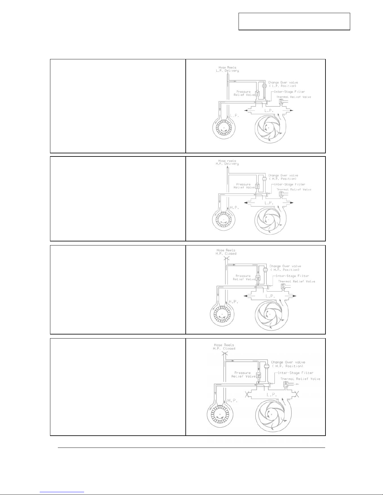
The Godiva WT Series two-stage pump is a dual pressure pump. It can be used for
high volume, low pressure (LP) output or for low volume, high pressure (HP) output,
or both simultaneously. When the pump is running, LP flow is always available, but
HP is available only if the HP selector valve is in the closed position. The HP outlet
is separate from the LP outlets and is mounted on the top rear of the pump. It is
recommended that if HP is not required, then the change over valve is left in the
open position, as this will reduce engine and transmission loads and noise.
A pressure relief valve is fitted which allows a small amount of water to circulate
back to the LP stage to prevent the pump from developing excessive pressure,
should it be operated at HP against closed HP discharge valves.
The pump is generally driven in a clockwise direction viewed from the drive end. The
pump may also be specified configured to rotate in a counter-clockwise direction.
The pump drive shaft, which runs on angular contact and roller bearings in an oil
bath, is of stainless steel. Shaft sealing of the pump is by a special Godiva
mechanical seal face, which ensures efficiency and long life without adjustment. The
electronic tachometer sender is mounted adjacent to the drive flange.
Priming of the pump is achieved automatically by means of a pair of positive
displacement piston primers mounted on either side of the bearing housing. These
primers begin to operate as soon as the pump drive shaft begins to rotate, driven by
an eccentric bearing on the pump shaft. Air within the pump will be expelled and as
long as the suction connections have been made and the hose end submerged, the
pump will prime and the pistons will disengage by 1.5 bar. The pump should be
primed at any speed between 1000-2500 rpm. The pump speed should not be
increased further until the primers have disengaged and the pump is primed.
An optional alternative priming system – the Godiva water ring primer – is available
in place of the piston primer system. With the water ring primer, when the pump is
started, the primer shaft is driven by its fibre driving wheel which contacts the pulley
on the pump drive shaft and is lifted off by a disengaging cylinder as the pump is
primed and pressure builds up in the pump. An alternative to friction pulley drive is
belt-drive through an electro-magnetic clutch. When the pump is primed and
pressure builds up, a pressure switch turns off the clutch drive.
Non-return valves are built into both the piston and water ring priming systems to
prevent air flowing back through the primers, thus “breaking the prime”.
As the pump is reduced to idling and the pressure within the pump decreases, the
pistons will once again reengage to act as a pump and discharge any water
remaining in the pump.
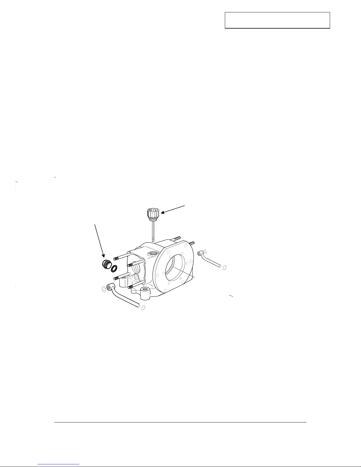
HP delivery is from a connection mounted on the top rear side of the pump which is
threaded internally to 1 ¼" BSP or rearwards via a flange.
A World Series Options Manual is available which shows many of the standard
specifications currently available together with an indication of their positions relative
to datum points on the pump.
©Hale Products Europe LTD, Warwick
GP/146/99
WTmaint - Issue9. 10-2005October 2005
8

MAINTENANCE MANUAL
GP/146/99. Issue 9. Octobe
r
2005
LUBRICATION
The oil bath provided for the pump drive shaft bearings has a capacity of 0.75 litres
(1.3 pints) and should be topped up when necessary with 10w/40-15w/40 multigrade
engine oil. It is recommended that the oil bath is drained and refilled with fresh oil
about every twelve months.
To check the oil level, remove the filler/dipstick which is situated on the bearing
housing immediately behind the pump body. Add fresh oil through the oil filler
aperture until it reaches the dipstick level. Refit the oil filler plug securely. Run the
pump for a short period and then re-check the oil level. The oil level should be
checked with the dipstick screwed down into its fixed position.
The oil drain plug is situated at the rear of the bearing housing below the pump drive
flange as shown on Fig A.
Fig A Bearing housing oil filler, level and drain plug
©Hale Products Europe LTD, Warwick
GP/146/99
WTmaint - Issue9. 10-2005October 2005
9
Oil drain plug
Oil filler / dipstick

MAINTENANCE MANUAL
GP/146/99. Issue 9. Octobe
r
2005
PROTECTION AGAINST FROST
As a precautionary measure, when frost is anticipated, drain all water from the pump
and its ancillaries.
The pump is drained by removing the drain plug from the base of the volute. It is
highly recommended that this is removed and the volute fitted with a drain valve
system terminating with a ball valve at a convenient location on the vehicle. The
high-pressure side of the pump will automatically drain down into the low- pressure
side (patent applied for), so that only one pump drain point is required.
If the primer exhaust is piped away to above the primer outlets, these must be
provided with drain valves.
In order to completely drain the piston priming system the pump should be idled for a
few seconds after use with no water in the volute and the drain valve open. This ‘dry
prime’ will then evacuate all residual water from the priming system.
If the water ring primer is fitted, it is drained by removing the drain plug at the base of
the water trap housing.
It is not recommended that the pump be retained full of water since this could result
in freezing in cold climates.
IMPORTANT: It is essential to carry out the pump tests detailed in Section 13
whenever any part of the pump or priming system is dismantled.
This will ensure that reassembly has been carried out correctly
and that there are no leaks.
©Hale Products Europe LTD, Warwick
GP/146/99
WTmaint - Issue9. 10-2005October 2005
10

MAINTENANCE MANUAL
GP/146/99. Issue 9. Octobe
r
2005
Section 1
SUCTION TUBE AND FRONT WEARING RING
To Remove
To remove the suction tube, remove priming pipe and foam inductor (if fitted) from
RH side, and Tank Fill line (if fitted) from LH side of suction tube. Remove the M10
nuts, spring washers and plain washers to allow the withdrawal of suction tube and
front wearing ring if necessary. The front wearing ring has two identical O rings, one
of which is face mounted towards suction tube and the second being in a groove
behind its flange.
To Refit
Clean all flange faces and lightly grease new O rings before refitting. If it should be
necessary to renew the fibre bush in the centre of the front wear ring, the old bush
should be drifted out and a new bush inserted by the use of the special mandrel PLA
2336. The end of the bush nearest the impeller must be flush with its housing.
Section 2
WEARING RING MAINTENANCE
Check the large internal diameter of the wearing ring in several places (see Fig 2-1).
If it exceeds dimension ‘A’, 140.6 mm for WT 2010 and WT 3010 model pumps, or
171.1 mm for WT 4010 and 187.6mm for WT6010, at any point, the wearing ring
must be renewed.
A
Fig 2-1
To Refit
Refitting is a reversal of the removal instructions. Use new O rings lightly greased
before refitting and should be fitted with diameter A towards the impeller.
©Hale Products Europe LTD, Warwick
GP/146/99
WTmaint - Issue9. 10-2005October 2005
11

MAINTENANCE MANUAL
GP/146/99. Issue 9. Octobe
r
2005
SECTION 3
LOW PRESSURE IMPELLER AND REAR WEAR RING
To Remove
In order to access the low pressure impeller, it is only necessary to disconnect
pipework as described in Section 1, then remove the 12 off M12 bolts from the volute
cover plate which may then be withdrawn together with suction tube etc giving direct
access to the low pressure impeller leaving the volute body in situ. Remove the
tacho sender and fit shaft locking screw (Tool No 60275/11) locating the spigot into
one of the drive flange holes. Remove the impeller nut and the pair of lock washers
and withdraw the impeller from the keyed pump shaft. It may be necessary to use
special tool 60275/04 to remove the impeller from the pump shaft.
Maintenance
Check the wearing diameter on the impeller in several places (see Fig 3-1). If the
diameter is less than stated in the table below, a new impeller should be fitted.
Fig 3-1 Checking the wearing diameters of the low pressure impeller
B
C
A
Pump Type Front Diameter (A) Rear Diameter (B) Hub Diameter (C)
WT2010 and
WT 3010 139.3 mm
135.3 mm
67.5mm
WT4010
169.5 mm
170.8 mm
67.5 mm
WT6010 188.6 mm 188.5 mm
67.5 mm
©Hale Products Europe LTD, Warwick
GP/146/99
WTmaint - Issue9. 10-2005October 2005
12

MAINTENANCE MANUAL
GP/146/99. Issue 9. Octobe
r
2005
To Refit
Refitting is a reversal of the removal instructions. It is recommended that new O
rings are fitted to impeller end face and shaft and a new pair of lockwashers are
fitted before refitting the impeller nut which should be tightened to 400Nm (295 lbs ft)
torque. To refit front cover plate, a new O ring should be fitted to the cover plate
spigot before assembly.
Rear Wear Ring
The rear wear ring (accessible removal of the low pressure impeller) is retained by 4
off M8 socket head screws. After removal of these screws, the rear wear ring may
be jacked out by means of two screws inserted into the adjacent tappings.
Fig 3-2 Checking the wearing diameters of wear ring
2010/3010 X 4010 X
Y Y
Pump Type Dia X Dia Y
WT2010 and
WT 3010 133.9mm 69.5mm
WT4010
169.5mm 69.5mm
WT6010 186.8mm 69.5mm
To Refit
Clean all surfaces before re-assembly. Apply Loctite 242 to screw threads before
refitting and tightening.
©Hale Products Europe LTD, Warwick
GP/146/99
WTmaint - Issue9. 10-2005October 2005
13

MAINTENANCE MANUAL
GP/146/99. Issue 9. Octobe
r
2005
Section 4
HIGH-PRESSURE IMPELLER
To Remove
With the volute cover plate and the low pressure impeller removed (Section 3)
unscrew the twelve M10 socket head cap screws securing the high pressure impeller
cover plate. Insert 2 M8 socket screws into the extractor holes in the cover plate and
screw them in evenly until the cover plate moves forward. The cover plate can now
be lifted off. Remove the cover plate and high pressure impeller, using tool number
60275/05 where necessary. Clean the cover plate and pump body jointing faces.
Maintenance
The high pressure impeller requires precise setting to achieve its rated output and to
avoid possible trouble in service. If no new parts have been fitted, ie pump body,
mechanical seal assembly, cover plate or high pressure impeller, the original shims
as fitted to the pump shaft may be inserted and a check on clearances carried out as
detailed in (b) and (c) below. If any of the above components have been changed,
carry out the entire sequence as follows:
(a) With the pump body assembled to the bearing housing, place the original
shims, or a selection of shims from the four available thicknesses (0.051mm,
0.127mm, 0.26mm and 0.381mm) (0.002in, 0.005in, 0.010in and 0.015in) on
to the drive shaft. The accumulative thickness of shims must total at least 1.0
mm before the impeller nut is tightened to ensure that the high pressure
impeller is not damaged.
(b) On no account should the mechanical seal seating ring (mounted within the
rear face of the HP impeller) be disturbed unless replacement of mechanical
seal components is contemplated. The mating faces of the mechanical seal
components may be cleaned with a non-abrasive, non-oily cleaner and wiped
dry with a lint-free cloth. Before assembly, moisten the face of the carbon
seal with clean water. Slide the impeller on to the drive shaft, followed by
spacer Tool No 60275/03 onto the shaft, followed by the large shaft nut.
Tighten the nut.
©Hale Products Europe LTD, Warwick
GP/146/99
WTmaint - Issue9. 10-2005October 2005
14

MAINTENANCE MANUAL
GP/146/99. Issue 9. Octobe
r
2005
(c) Using a depth micrometer, measure the clearance between the pump body
cover plate seating face and the impeller blade edge (see Fig 4-1). The depth
micrometer should read 0.23/33mm (0.009-0.013in). If the measurement is
more than this, remove the nut, washer and spacer, add shims to correct the
clearance, re-assemble and re-check. If the measurement is less, remove
shims to correct the clearance and re-check at 90° intervals. Rotate the
impeller a quarter of a turn and check again.
Fig 4-1 Checking the clearance of the high pressure impeller
Impeller clearance 0.23/0.33 (0.009”/0.013”)
©Hale Products Europe LTD, Warwick
GP/146/99
WTmaint - Issue9. 10-2005October 2005
15

MAINTENANCE MANUAL
GP/146/99. Issue 9. Octobe
r
2005
To Refit
When the correct clearance has been obtained, fit the cover plate. After ensuring
the joint face (A) on the pump body and the joint face on the cover plate are clean,
smooth and free from deformation, align the holes in the cover plate with the holes in
the pump body and clamp, using twelve M10 x 1.5mm stainless steel socket head
screws tightened to a torque of 57nm (42 lbs ft).
Spin the impeller to check for fouling, then remove the nut and spacer tool.
©Hale Products Europe LTD, Warwick 16
Note: the clearance between the impeller and the cover plate should be set at 0.23/0.33
(0.009”/0.012”) shimming where shown.
Impeller Clearance
Spacer - used only for
clamping impeller while
clearances are being checked
Impeller Shims
Clamping Sleeve
Impeller
Cover Plate
Face A
Fig 4-2 Assembly and clearances of the high pressure impeller.
Section 5
CARBON SEAL AND SEATING ASSEMBLY
When the high pressure impeller is removed, the mechanical carbon face seal is
accessible for examination. In the event of excessive leakage past the carbon seal
and out of the drain hole in the pump head, remove low pressure and high pressure
impellers per Sections 3 and 4. Examine the carbon seal. If the face of the carbon
seal seating ring is scored, it is essential to replace it and to fit a new seating ring
which is mounted within the rear face of the high pressure impeller. To remove the
carbon seal seating ring, remove two M6 nyloc nuts and washers and gently remove
it, taking care not to lose the wave spring. The stationary carrier may be left in place
if only the wearing faces are being replaced.
GP/146/99
WTmaint - Issue9. 10-2005October 2005

MAINTENANCE MANUAL
GP/146/99. Issue 9. Octobe
r
2005
The silicon carbide ring fitted in the rear side of the HP impeller may be levered out,
by means of a small instrument screwdriver inserted between the ring and its rubber
cup.
Reassembly of the seal is completed as described below. Please note: Mechanical
Seals are precision engineered devices and extreme care must be taken to ensure
that no damage occurs to the lapped faces.
Read the fitting instructions before installation of the seal.
Ensure that the lapped faces are absolutely clean throughout the entire installation.
Soiled faces must to be cleaned with appropriate degreasing cleaner and soft tissue.
Fig 5-1Carbon seal
and seating assembly
1. Ensure that the Pump Body (A) and High Pressure Impeller (B) bores are clean
and free from burrs and sharp edges , see Fig 5-1.
2. Lubricate the O Ring (C) with a suitable lubricant and carefully assemble the
Seal Head Assembly (D) into the Pump Body (A), lining up the cutouts in the
Seal Head Assembly (D) with the threaded Studs (E).
3. Fit Washer (F) to each of the Studs (E) followed by the Lock Nuts (G). The lock
nuts should be tightened half a turn at a time so that the Seal Head Assembly
(D) is pulled squarely into the Engine Housing. Ensure that the Lock Nuts are
fully secured.
4. Ensure Carbon Face (H) is clean and free from grease, if not use a degreasing
cleaner and soft tissue. Apply clean water to the carbon face.
5. Take Impeller (B) and carefully push the Mating Ring Assembly (I) into the bore
using Fitting Tool Number 60275/08. Ensure that the Face of the Mating Ring
Assembly is fitted squarely in the impeller housing within 0.1mm.
6. Carefully fit the High Pressure Impeller onto the shaft and continue with pump
build.
©Hale Products Europe LTD, Warwick
GP/146/99
WTmaint - Issue9. 10-2005October 2005
17

MAINTENANCE MANUAL
GP/146/99. Issue 9. Octobe
r
2005
Section 6
VOLUTE BODY
It is extremely unlikely in normal servicing that the volute body will require to be
removed, but in the event of removal the front cover plate should be removed as in
Section 3. The volute is mounted on to the high pressure pump body by means of
twelve studs, nuts and washers. The seal at both front and rear faces of the volute is
by O ring seals, which should be replaced if the joint face is disturbed. This volute
may be mounted on either standard rotation pumps or reverse rotation pumps, and
must be fitted the correct way round (see the cast on arrow near to the manifold
connecting face, normally on the right hand side). The 12 mounting studs should
always face the rear of the pump.
©Hale Products Europe LTD, Warwick
GP/146/99
WTmaint - Issue9. 10-2005October 2005
18

MAINTENANCE MANUAL
GP/146/99. Issue 9. Octobe
r
2005
Section 7
LOW PRESSURE MANIFOLD AND FILTER HOUSING
To Remove
Assuming that the HP pump discharge connections have been disconnected
together with gauge, thermal relief and foam connections, it is necessary to remove
the primer discharge pipe from the filter housing to the HP pump body. Remove 10
off M8 bolts to remove the filter body and bypass housing assembly. The low
pressure manifold is connected to the volute body by means of 4 off M10 bolts
surrounding the thermal relief valve and 2 M10 stainless steel socket head cap
screws inside the manifold casing (these 2 screws are fitted with bonded seals to
prevent leakage). The manifold may now be removed. The gasket between the
manifold and the filter housing will require renewal at this stage. The seal between
the volute body and manifold is an O ring.
Towards the rear of the manifold are 2 transfer tubes each sealed by O rings located
within the castings.
The main outlets to the manifold (6 off) are sealed by means of O rings, seated in
grooves in the manifold faces.
Reassembly
When reassembling the manifold, all O rings should be replaced and Loctite 242
should be applied to all threads before refitting.
Filter Housing
The housing contains the main low pressure filter and the primer disengagement
filters, both accessible from the front panel area. These filters, however, must not be
removed whilst the pump is in operation.
The flow across both filters is from outside to inside the cylindrical profiles. The
smaller filter is intended to restrict particle size in water entering the primer
disengaging circuit, whilst the larger filter prevents large particles from entering the
high pressure stage. During pump operation in low pressure mode, and at any time
that the pressure relief valve is open, a flow of water is directed across the large
filter, thus helping to flush the exterior of the filter.
©Hale Products Europe LTD, Warwick
GP/146/99
WTmaint - Issue9. 10-2005October 2005
19

MAINTENANCE MANUAL
GP/146/99. Issue 9. Octobe
r
2005
The change over valve is clamped between the filter housing and the bypass
connector housing and is retained by 4 off M10 bolts. Also constrained between the
2 housings is the cylindrical pressure relief valve and sealed on its outside diameter
by 2 O rings. This component should be treated as a single item and, for safety
reasons, must not be stripped down (due to the strong internal spring). It must be
reinstalled with its longest end towards the filter housing. The location is by means
of an external circlip.
The high pressure outlet is optional as a vertical 1.25” BSP tapping or a rear facing
square flange intended as a facing for an anti-surge valve, which may be supplied as
a single 1.25” BSP or twin 1.0” BSP outlet and AFFF valve mounting.
©Hale Products Europe LTD, Warwick
GP/146/99
WTmaint - Issue9. 10-2005October 2005
20
This manual suits for next models
7
Table of contents
Other Godiva Water Pump manuals
Popular Water Pump manuals by other brands

Pfeiffer Vacuum
Pfeiffer Vacuum HiPace 1800 operating instructions

Grundfos
Grundfos DDI 209 Installation and operating instructions

Roth
Roth ROTILABO CR-DS 40 Operation manual

Simer
Simer 5020B-04 owner's manual

Sulzer
Sulzer 100 Installation and operating instructions

Reefe
Reefe VSRE40-60 Exploded View & Instruction Manual