Goldine Controls Aqua Solar AQ-SOL-LV Installation manual

Electronic Solar Control Center
Operation and Installation Manual
formodels
AQ-SOL-LV
AQ-SOL-LV-TC
AQ-SOL-LV-SP
AA
AA
AQUAQUA
QUAQUA
QUA
SS
SS
SOLAROLAR
OLAROLAR
OLAR
TM
LDLINE
CONTROLS INC.
G

IMPORTANTSAFETYINSTRUCTIONS
When using this electrical equipment, basic safety precautions should always be
followed, including the following:
•READAND FOLLOWALL INSTRUCTIONS
•Disconnect allAC power during installation.
•Warning – To reduce the risk of injury do not permit children to use this
product unless they are closely supervised at all times.
•Agreen colored terminal marked “EARTH” is located inside the wiring
compartment. To reduce the risk of electrical shock, this terminal must be
connected to the grounding means provided in the electrical supply
service panel with a continuous copper wire equivalent in size to the
circuit conductors supplying the equipment.
•All field installed metal components such as rails, ladders, drains, or other
similar hardware within 3 meters of the pool, spa or hot tub shall be
bonded to the equipment grounding bus with copper conductors not
smaller than 8 AWG US/ 6 AWG Canada.
SAVE THESE INSTRUCTIONS

Table of Contents
SPECIFICATIONSSPECIFICATIONS
SPECIFICATIONS
SpecificationsSpecifications
Specifications ......................................................................1
OPERATIONOPERATION
OPERATIONOPERATION
OPERATION
ControlsControls
ControlsControls
Controls ...............................................................................2
Temperature DisplayTemperature Display
Temperature Display ........................................................3
INSTALLATIONINSTALLATION
INSTALLATION
MountingMounting
MountingMounting
Mounting ..............................................................................4
WiringWiring
WiringWiring
Wiring ..................................................................................4
Jumper SettingsJumper Settings
Jumper Settings ..................................................................9
TROUBLESHOOTINGTROUBLESHOOTING
TROUBLESHOOTING
TroubleshootingTroubleshooting
Troubleshooting ..............................................................10
WARRANTYWARRANTY
WARRANTYWARRANTY
WARRANTY
Five Year Limited WarrantyFive Year Limited Warranty
Five Year Limited Warranty...........................................12

1
Aqua Solar Digital Solar Control System
TheAqua Solar Digital Solar Control System is a differential temperature control for
solar heating of pools, spas, and hot tubs. The Aqua Solar is available in 3 models;
AQ-SOL-LV,AQ-SOL-LV-TC andAQ-SOL-LV-SP. Thesemodelsprovidedifferential
temperature control with an adjustable calibrated water temperature high limit. Both
offer a built-in digital display for solar, water, and ambient temperature information as
well as programmable set point temperature. Automatic nocturnal cooling (for pools
that overheat in hot climates) and recirculate freeze protection functions can be en-
abled/disabledvia internal jumpers. TheAQ-SOL-LV-TC additionally provides a filter
pump time clock, programmable in 15-minute intervals with multiple ON/OFF times.
The AQ-SOL-LV-SP model provides a solar priority function—one of the optional
high voltage relays can be used to remove power from the conventional heater when-
eversolarheating is available. This maximizes the heat contribution from solar. Front
panel indicator LED’s also provide immediate feedback of system state such as heat-
ing, cooling, and sensor fault.
Specifications
Power: 105-130VAC, .5A 50/60Hz. or
195-250VAC, .3A 50/60Hz
Valve Output: 24VAC, 20VA, .85A max.
Industry standard 3 pin connector
RelayOutputs: DPSTisolated contacts; 3HP@240V, 1.5HP@120V,booster pump,
pool sweep interlock, or filter pump; 1 relay supplied withAQ-
SOL-LV-TC, maximum of 2; order relays separately (part no.AQ-
RELAY); relays are industry standard
Sensors: 2 required for "SOLAR" and "POOL" temperatures; 3rd sensor
("AUX") is optional—for display and/or recirculate freeze
protection; (all sensors are thermistor type, 10K@25ºC/77ºF,
additional freeze snap switches may be wired in series with the
"AUX" sensor when used for recirculate freeze protection)
Field Selectable options
C/F Temperature display in Celsius or Fahrenheit (factory default)
Cooling Enables or disables (factory default) operation to cool the pool
Recirc. Frz. Enables or disables (factory default) recirculate freeze protection
Solar Override Enables or disables (factory default) override of the filter pump
relay when solar heat is available.
Control Logic
Heat diff.: 4ºF on, 1.5ºF off
High Limit: 70-104ºF calibrated scale
Recirc.freeze: On when AUX sensor less than or equal to 34ºF
Off when AUX sensor greater than or equal to 36ºF
Cooldiff.: -8ºFon, -3ºF off

OPERATION
TheAqua Solar is a fully automatic solar heating control which requires minimal set
up or adjustment under normal operating conditions. Typically the following is re-
quired:
1. Set the main switch toAUTO
2. Set the “Desired Temperature” knob to the desired temperature for the pool
3. Set the time clock for the correct time, the desired hours of filtration, and
“auto” operation (modelAQ-SOL-LV-TC only)
The “Heating” LED will show when the pool is being solar heated. If your pool has
a pool sweep, theAqua Solar will turn it off for approximately 6 minutes when solar
heat is turned on. This will allow air to be purged from the system.
Controls and Displays
MAIN SWITCH
ON: TheAqua Solar directs water through the solar collectors regardless of
desired temperature setting. Both the “Heating” and “Cooling” LED’s will be
on. For model AQ-SOL-LV-TC, this also turns on the filter pump.
AUTO: For normal operation. In this position, theAqua Solar will operate
automatically based on the solar and pool temperatures.
OFF: TheAqua Solar ceases solar heating or cooling (if enabled). Recircu-
late freeze protection (if enabled) will still operate normally. This switch does
NOT remove power from the unit--to service the equipment, disconnect power
at the main circuit breaker.
DESIRED TEMPERATURE
Set the desired pool temperature. The digital display will show the exact tempera-
ture while rotating the Desired Temperature knob. The display reverts back to the
default pool temperature display a few seconds later.
TIMECLOCK (modelAQ-SOL-LV-TC only)
The time clock controls the hours of operation for the filter pump. The pump can
be programmed in 15-minute intervals with multiple on/off periods per day. Per
NSPI standards, the pump should run long enough each day to filter all of the water
in the pool each day.
Set the Aqua Solar timeclock to the correct time by rotating the clock dial in a
clockwise direction. The internal “hands” show time at a glance and the arrow
(approximately 2 o’clock on dial) point indicatesAM/PM. Set the pump on/off time
using the series of small slide "trippers" located around the outside of the
timeclock. Each tripper controls a 15-minute interval.
OFF- Push trippers IN (toward center)
ON - Pull trippers OUT (away from center)
2

3
TIMECLOCK--MANUALCONTROL
The manual control can override the timer and is located at approximately the 4
o’clock position.
“1” (up) - pump ON
“ ” (center) - timer controls pump
“0” (down) - pump OFF
NOTE: If the solar override function is enabled, then theAqua Solar may keep the
filter pump running even though the time clock is “off”
TEMPERATURE DISPLAY
The temperature display normally displays the pool temperature. Push the small but-
ton next to the display to cycle through the various displays. If a temperature sensor
is not wired to the Aqua Solar, or the sensor is not functioning properly, the error
message "Err" will be displayed for that sensor. If the button is not pushed for 30
seconds, the display will automatically revert back to pool temperature. The ex-
ample below shows a typical display:
Normal, default display indicates Pool temperature:
1st button push will show Solar Collector temperature:
2nd button push will show Aux temperature (if used):
3rd button push will show "Desired Temperature":
4th button push will show software revision number:
5th button push will loop back to show Pool temperature.
LED INDICATORS
Power: Input power is applied to theAqua Solar.
Heating: Solarheating is active. If both Heating and Cooling areon, the
switch is in the ON position.
Cooling: Nocturnal Cooling is active. If both Heating and Cooling are
on, the switch is in the ON position.
SweepInterlock: The pool sweep is turned OFF for approximately 6 minutes to
allow air to purge from the system.
PoolSensor: A problem is detected with the pool sensor (open or short
circuit).
Solar Sensor: A problem is detected with solar sensor (open or short circuit).
AuxSensor: Aproblem is detected with theAUX sensor (short circuit, only
when used for recirculate freeze protection).

4
INSTALLATION
Mounting
The Aqua Solar is designed for outdoor use. Mount the enclosure vertically with the
knockouts facing downward. For safety, theAqua Solar must be a minimum of 5 feet
(horizontally) from the pool or spa.
Power input
Turn off power at circuit breaker before wiring. Follow NEC and all local electrical
codes. Wire to either 120VAC or 240VAC per the diagram below. If theAqua Solar
is being powered from the same circuit as one of the pumps, wire to the relay first and
then jumper over the Aqua Solar terminal block. Do NOTuse theAqua Solar termi-
nal block as a junction for pump power, the terminal block is not rated for high amps.
Be sure to connect the earth ground to the green terminal.
Outputwiring tosolar divertervalve
Most installations use a solar valve, which diverts water through the collector panels
when solar heat is available. For Goldline®, Jandy®, and Compool®valve actuators
(with wire end connectors), two 3-pin connectors are supplied. Plug the actuator into
one of the Aqua Solar's two 3-pin connectors (see diagram above for location of
connectors). If the valve operates opposite to the way it is supposed to, disconnect
and plug into the other connector.
Jandy®is a registered trademark of Waterpik Technologies, Inc.
Compool®is a registered trademark of Pentair Pool Products, Inc.
120VAC
Booster Pump
Pool Sweep
Rev
Valve
Output
Relay
Control
Outputs
Input
Power Temperature
Sensor
Inputs
Fuse (2A, Slo-Blo)
Aux
Filter Pump
Fwd
Pool
Solar
240 VAC
Ground
}
Cooling
Recirculate/
Freeze Protection
Celsius/
Fahrenheit
Solar
Override
(heater interlock for -SP model)

SensorMountingand Wiring
Most installations use a Goldline "PC" type sensor for both the "SOLAR" sensor and
"POOL" sensors. The "AUX" sensor is required for optional recirculate freeze
protection(seedescriptionofthisfunctiononpage9). Otherwise, the "AUX" sensor
can simply display the ambient air temperature.
Any 10K ohm Goldline sensors may be used. Wire should be twisted pair 20AWG.
Sensor wiring run outdoors must be rated for outdoor use and ensure that the wire
connectors are protected from the weather. For long runs or runs near other electrical
wiring use shielded cable (Belden 8428 for outdoor use). Ground the shields to the
Aqua Solar's ground screw.
HighVoltage RelayOutput Wiring
Amaximum of two high voltage relays (industry standard) may be added to the AQ-
SOL-LV. TheAQ-SOL-LV-TC model comeswith onerelayfor the filter pump control
already installed and one additional relay may be added. Order additional relays
separately (Goldline p/n "AQ-RELAY"). The relays are industry standard and are
double pole, single throw meaning that they can make/break both legs of a 240VAC
circuit. Screw the relays into the mounting bracket and connect the coil to the proper
connector for these desired functions:
BOOST: This relay controls a booster pump for systems where the main filter pump
does not have enough power to pump water through the collector array. The boost
pump turns on 30 seconds after solar heating/cooling turns on.
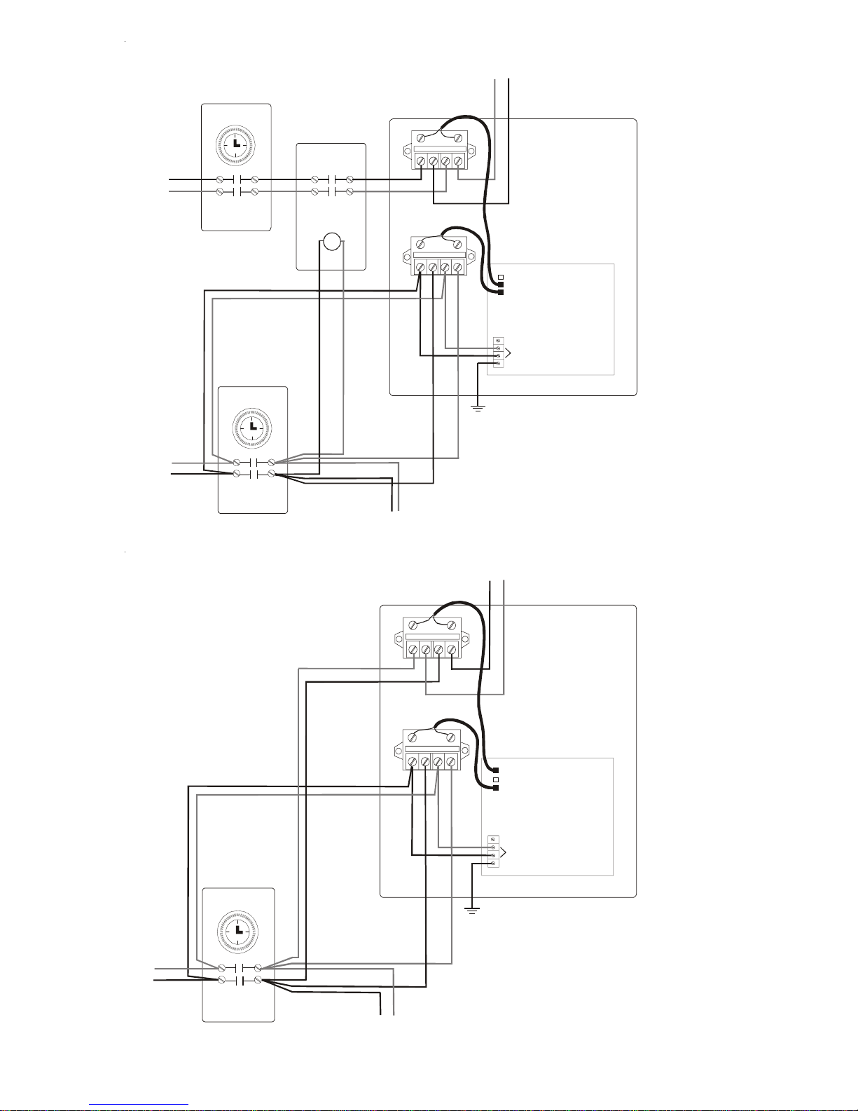
AQ-SOL-LV: For most systems, simply connect theAqua Solar power to the LOAD
side of the filter pump timer. If theAqua Solar is connected to LINE power (typically
when "Recirculate Freeze" or "Solar Override" features are also being used), then the
input power to the boost pump relay should be connected to the LOAD side of the
filter pump timer. See wiring diagram on page 6 (bottom).
AQ-SOL-LV-TC: The Aqua Solar will automatically ensure that the filter pump is
running before turning on the boost pump. See wiring diagram on page 7.
SWEEPINTERLOCK: Therelayiswiredinserieswiththepoolsweepandturnsthe
pool sweep off for approximately 6 minutes whenever the solar turns on. This pre-
vents the pool sweep pump from losing prime while air is being purged from the solar
collector array. For model,AQ-SOL-LV-TC the relay will also turn the pool sweep off
whenever the filter pump is turned off. See wiring diagrams on page 6 (top) and on
page 8 for typical wiring.
FILTER PUMP: The function of this relay varies with the model of theAqua Solar. If
the "Solar Override" is enabled (see "Jumper Settings"), theAqua Solar will override
the time clock and turn the filter pump on when there is a call for solar heating. If
"RecirculateFreeze" protection is enabled, theAqua Solar will turnthe pumpand solar
valve on during freezing conditions.
AQ-SOL-LV: This relay should be wired in parallel with the filter pump timeclock
contacts as shown on page 6. Be careful to make sure the phases do not get reversed.
AQ-SOL-LV-TC: Thisrelayisthe primary control for the filter pump—there is no other
timer. The Aqua Solar will operate the filter pump according to the "trippers" set on
the built-in timeclock in addition to the optional "Solar Override" and "Recirculate
Freeze" options. 5

6
Booster Pump
Pool Sweep
Filter Pump
Ground
Pool Sweep
Timer
Contactor
(240 VAC Coil)
120/240
VAC
240
VAC
Filter Pump
Timer Pool Filter
Pump
Pool Sweep
Pump
Aqua Solar
(AQ-SOL-LV)
AQ-SOL-LV
with Solar Override & Pool Sweep Interlock
Be careful not to cross phases
on filter pump wiring
240 VAC
Booster Pump
Pool Sweep
Filter Pump
Ground
240
VAC
Filter Pump
Timer Pool Filter
Pump
Boost
Pump
Aqua Solar
(AQ-SOL-LV)
AQ-SOL-LV
with Solar Override & Boost Pump
Be careful not to cross phases
on filter pump wiring
240 VAC
Boost relay power
connected to LOAD
side of Filter Pump
Timer to ensure that
boost pump only runs
when filter pump is
runnning

7
Booster Pump
Pool Sweep
Filter Pump
240
VAC
240
VAC
Filter
Pump
Solar
Booster
Pump
A
qua Solar
(AQ-SOL-LV-TC)
AQ-SOL-LV-TC
with filter pump & booster pump relays
NOTES:
1) Do not useAqua Solar terminal block as a junction for pump wiring.
2) Most codes require that each pump be on a separate circuit.

8
Booster Pump
Pool Sweep
Filter Pump
240
VAC
Filter
Pump
Sweep
Pump
Aqua Solar
(AQ-SOL-LV-TC)
AQ-SOL-LV-TC
with filter pump & pool sweep relays
NOTES:
1) Do not useAqua Solar terminal block as a junction for pump wiring.
2) Most codes require that each pump be on a separate circuit.
3) Aqua Solar will ensure sweep pump runs only when filter pump is running.
4) Sweep pump will turn off for approximately 5 minutes when solar turns on.
Ground
240 VAC
Pool Sweep
Timer
120/240
VAC

9
JumperSettings
The jumpers that enable/disable optional control features are located on the right side
of the main circuit board (see page 4). The factory default for all functions is "dis-
abled" (each jumper will be on a single pin). To "enable" a function, simply take the
designated jumper and place it over both pins.
COOLING: Ahigh voltage relay for filter pump control is usually required to imple-
ment this function. If Cooling is enabled, theAqua Solar will cool the pool by turning
on the filter pump and diverting the flow through the collector array whenever the
"POOL" temperature is WARMER than the “Desired Temperature” settingAND the
"SOLAR" sensor is COOLER than the pool water.
RECIRCULATE FREEZE PROTECTION: A high voltage relay connected to
the "FILTER PUMP" output and theAUX temperature sensor are required to imple-
ment this function. If enabled, theAqua Solar will turn the filter pump on and operate
the solar diverter valve whenever freezing conditions are detected (AUX sensor be-
low 35ºF). See diagram on page 6 for typical relay wiring. When recirculate freeze
protection is enabled and theAqua Solar senses a freeze condition at theAUX sensor,
it will circulate the pool water continuously through the entire filtration plumbing
loop including the solar collector panels. While this type of freeze protection is
usually adequate in relatively mild climates, it is extremely important that the AUX
sensor be properly placed and that the homeowner realize that the system is unpro-
tected in the event of a power failure. Goldline Controls highly recommends that one
or more “freeze snap switches” (models GC-1 or GC-2) be placed in areas with sus-
ceptible plumbing (example: areas that may be shaded, or get more wind exposure)
and that these sensors be wired in series with the AUX sensor. Recirculate freeze
protection is NOT recommended in climates where freezing temperatures are
common or last for extended periods.
WARNING--If recirculate freeze protection is NOT selected, then you are rely-
ing on the collectors naturally draining to provide freeze protection. It is very
important that you use a non-positive seal valve or drill a hole in the diverter of
a positive seal valve to allow the collectors to drain. This will NOT work if the
collectors are located below the water level of the pool.
CELSIUSDISPLAY: This will change the temperature display to degrees--Celsius.
The factory default is degrees--Fahrenheit.
SOLAR OVERRIDE: A high voltage relay connected to the "FILTER PUMP"
output is required to implement this function. When "Solar Override" is enabled, the
Aqua Solar will overridethe filter pump timeclock (external timeclock forAQ-SOL-
LV or internal timeclock forAQ-SOL-LV-TC) and turn the filter pump on whenever
there is a call for solar heating or cooling. During periods of on/off cloudy days this
may result in the pump turning on and off multiple times. It is also possible that the
pump could turn on during hot night conditions. To prevent rapid on/off cycling of
thefilter pump during cloudy conditions,the pumpwillalso remain on for a minimum
of10 minutes, and will remain off for a minimumof 2hours.

10
Troubleshooting
1. "Power"LEDoff:
Checkmainpower circuit breakers. Check to see if theAquaSolar power is connected
totheLOADside of the filter pump timer, in whichcase theAqua Solar will only be on
when the filter pump is on. Lastly, check the internal fuse which is located on the right
upper side of the main circuit board. If necessary, replace the fuse with a type 3AG, 2
amp, slo-blo fuse, which is available in most electrical or electronics stores.
2. "Heating"LEDisalwayson:
Check that the switch is in the “AUTO” position. Check the sensor temperatures:
The "Heating" LED should go off if the pool temperature is less than the "Desired
Temperature" OR if the solar temperature is less than the pool temperature. If the
sensors appear to giving incorrect readings, check the sensors using the temperature/
resistance/voltage chart on the back cover.
3. "Heating"LEDnevercomeson:
Verify that the switch is in the “AUTO” position. Check the sensor temperatures: The
"Heating" LED should turn on when the pool temperature is less than the "Desired
Temperature" AND the solar temperature is warmer than the pool temperature. The
exception is when solar override is being used (typically when the pool is filtered at
night, but the solar override function is used to turn the filter pump on during the day
whensolar heat is available): In this case, thereisa2hour minimum off time to prevent
rapid on/off cycling of the filter pump. If the sensors appear to giving incorrect
readings, check the sensors using the temperature/resistance/voltage chart on the
back cover.
4. "Heating"and"Cooling"LEDsonsimultaneously
This indicates that the main switch is in the "ON" position. The Aqua Solar will
operate the solar valve and the booster pump (if installed) regardless of the sensor
temperatures. Set the switch back to "AUTO" to resume normal operation.
5. "Heating"and "Cooling"LEDsflashingsimultaneously
This indicates that recirculate freeze protection is active (solar valve on, boost pump
on (if used), and filter pump on) due to the "AUX" sensor being less than 35ºF OR the
"AUX" sensor being disconnected OR any freeze snap switches wired in series with
the "AUX" sensor being open. If the "AUX" sensor is not connected OR a freeze
snap switch is open, the "AUX" temperature display will be " LO ". The Aqua Solar
will continue this operating mode until the "AUX" sensor rises above 35ºF AND all
freeze snap switches wired in series with the "AUX" sensor are closed. This function
operates regardless of the position of the "ON /AUTO / OFF" switch.
6. "Pool Sensor"LED onorflashing
"Err"onthepooltemperaturedisplay:
On continuously indicates a probable open circuit in the "POOL" sensor or wiring.
Flashing indicates a probable short circuit in the "POOL" sensor or wiring. In either
case digital pool temperature display will show as "PErr". The solar heating and
cooling functions will remain off until this problem is fixed, however, the recirculate
freezeprotection(ifenabledbythe jumper) will still operate properly. Use the chart on

11
the back cover to check the "POOL" sensor with a voltmeter (you don't need to
disconnect the sensor). Alternatively, you can disconnect the sensor and measure
the sensor resistance. Replace the sensor or fix the wiring as required. If the sensor
and wiring are both good, then the main circuit PCB may have a problem.
7. "SolarSensor" LED onorflashing
"Err"onthesolartemperaturedisplay:
On continuously indicates a probable open circuit in the "SOLAR" sensor or wiring.
Flashing indicates a probable short circuit in the "SOLAR" sensor or wiring. In either
case digital pool temperature display for the "SOLAR" sensor will show as "CErr".
The solar heating and cooling functions will remain off until this problem is fixed,
however, the recirculate freeze protection (if enabled by the jumper) will still operate
properly.
Use the chart on the back cover to check the "SOLAR" sensor with a voltmeter (you
don't need to disconnect the sensor). Alternatively, you can disconnect the sensor and
measure the sensor resistance. Replace the sensor or fix the wiring as required. If the
sensor and wiring are both good, then the main circuit PCB may have a problem.
8. "Aux Sensor"LED flashing
"Err"ontheAuxtemperaturedisplay:
Flashing indicates a probable short circuit in the "AUX" sensor or wiring. The digital
pool temperature display for the "AUX" sensor will show as "AErr". This error
indication only occurs when the "AUX" sensor is being used for recirculate freeze
protection. When the Aux sensor is shorted, the Aqua Solar will use the "SOLAR"
sensor as a backup freeze sensor and turn the recirculate freeze protection on when
the temperature is less than 60ºF.
Use the chart on the back cover to check the "AUX" sensor with a voltmeter (you
don't need to disconnect the sensor). Alternatively, you can disconnect the sensor and
measure the sensor resistance. Replace the sensor or fix the wiring as required. If the
sensor and wiring are both good, then the main circuit PCB may have a problem.
Technical Help
For help in installing, operating, or troubleshooting this control, you may call for
technical assistance at 888-921-POOL (7665). Goldline technicians are available
from 8AM to 8PM Eastern Time, Monday through Friday. You may call at other
times and leave a message and a technician will call you back as soon as possible.

12
Limited Warranty - Solar ControlsLimited Warranty - Solar Controls
Limited Warranty - Solar Controls
This warranty statement is applicable to all solar control products manufactured by Goldline
Controls, Inc., previously known as Independent Energy, Inc. (Goldline) on or after
November 1, 2001. See the appropriate warranty statement for other Goldline products or
for solar controls produced prior to November 1, 2001.
SolarControlsinstalledinUSAorCanada:
Goldline warrants its solar control products installed within the USA or Canada to be free from
defects in material or workmanship, under normal use and service for five years from date
of the initial system installation, provided it is installed in accordance with the Goldline
installation instructions and specifications provided with the product. If written proof of the
date of the initial system installation is not provided to Goldline, the manufacturing datecode
on the product will be the sole determinant of the date of the initial system installation.
If a product is defective, in workmanship or materials and is removed and returned freight
prepaid within three (3) years after the date of the initial system installation, Goldline Controls
will, at its option, either repair or replace the defective product and return it freight prepaid.
If the defective product is returned freight prepaid to Goldline more than three (3) years but
within five (5) years of the date of the initial system installation, Goldline, at its option, will
either repair or replace the defective product and will charge sixty percent (60%) of the current
list price for such repairs or replacements, plus shipping charges. The costs incurred in removal
and/or reinstallation of the product are NOT covered under this warranty.
SolarControlsinstalledoutsideoftheUSAorCanada:
Goldline warrants its solar control products installed outside of the USA or Canada to be free
from defects in material or workmanship, under normal use and service for one year from
date of the initial system installation, provided it is installed in accordance with the Goldline
installation instructions and specifications provided with the product. If written proof of the
date of the initial system installation is not provided to Goldline, the manufacturing datecode
on the product will be the sole determinant of the date of the initial system installation.
If a product is defective, in workmanship or materials and is removed and returned freight
prepaid within one (1) year after the date of the initial system installation, Goldline will, at
its option, either repair or replace the defective product and return it freight prepaid. The costs
incurred in removal and/or reinstallation of the product are NOT covered under this warranty.
Warrantyexclusions:
1. Material supplied or workmanship performed by others in the process of installation
2. Damage resulting from improper installation or control of loads exceeding the product
rating.
3. Problems resulting from failure to operate the products in accordance with recommended
instructions contained in product’s owners manual.
4. Problems resulting from tampering, accident, abuse, negligence, unauthorized repairs or
alterations, fire, flood, lightning, freezing, external water, war, or acts of God.
THE EXPRESS LIMITED WARRANTY ABOVE CONSTITUTES THE ENTIRE
WARRANTY OF GOLDLINE CONTROLS, INC. WITH RESPECT TO ITS SOLAR
CONTROL PRODUCTS AND IS IN LIEU OF ALL OTHER WARRANTIES, EXPRESSED
OR IMPLIED, INCLUDING WARRANTIES OF MERCHANTABILITY OR FITNESS FOR
A PARTICULAR PURPOSE. IN NO EVENT SHALL GOLDLINE CONTROLS, INC. BE
RESPONSIBLE FOR ANY CONSEQUENTIAL, SPECIAL OR INCIDENTAL DAMAGES OF
ANY NATURE WHATSOEVER.
NO WHOLESALER, AGENT, DEALER, CONTRACTOR, OR OTHER PERSON IS
AUTHORIZED TO GIVE ANY WARRANTY ON BEHALF OF GOLDLINE CONTROLS,
INC. THIS WARRANTY IS VOID IF THE PRODUCT HAS BEEN ALTERED IN ANY
WAY AFTER LEAVING THE FACTORY.
11/1/2001

092008B
Temperature/Resistance /Voltage
All Goldline controls use a 10K thermistor sensors. When disconnected from the
control, the sensor will read 10K ohms at 25ºC/77ºF. Refer to the chart below for
the resistance at other temperatures. For a given temperature, the resistance
reading should be accurate to ±1%. For a given resistance reading, the tempera-
ture reading should be accurate to ±0.5ºF. All voltage measurements (DC) must
be made with the sensor connected to the control and should be accurate to ± 2%.
°F Ohms
V
olts °F Ohms
V
olts °F Ohms
V
olts °F Ohms
V
olts
1 82,719 4.46 41 25,391 3.59 81 9,076 2.38 121 3,679 1.34
2 80,142 4.45 42 24,704 3.56 82 8,861 2.35 122 3,602 1.32
3 77,656 4.43 43 24,037 3.53 83 8,651 2.32 123 3,527 1.30
4 75,255 4.41 44 23,391 3.50 84 8,447 2.29 124 3,454 1.28
5 72,937 4.40 45 22,764 3.47 85 8,249 2.26 125 3,382 1.26
6 70,698 4.38 46 22,156 3.45 86 8,056 2.23 126 3,312 1.24
7 68,535 4.36 47 21,566 3.42 87 7,867 2.20 127 3,244 1.22
8 66,447 4.35 48 20,993 3.39 88 7,684 2.17 128 3,177 1.21
9 64,428 4.33 49 20,438 3.36 89 7,506 2.14 129 3,112 1.19
10 62,479 4.31 50 19,900 3.33 90 7,333 2.12 130 3,049 1.17
11 60,595 4.29 51 19,377 3.30 91 7,164 2.09 131 2,987 1.15
12 58,774 4.27 52 18,870 3.27 92 6,999 2.06 132 2,926 1.13
13 57,014 4.25 53 18,377 3.24 93 6,839 2.03 133 2,867 1.11
14 55,313 4.23 54 17,899 3.21 94 6,683 2.00 134 2,809 1.10
15 53,669 4.21 55 17,435 3.18 95 6,530 1.98 135 2,752 1.08
16 52,078 4.19 56 16,985 3.15 96 6,382 1.95 136 2,697 1.06
17 50,541 4.17 57 16,548 3.12 97 6,238 1.92 137 2,643 1.05
18 49,054 4.15 58 16,123 3.09 98 6,097 1.89 138 2,591 1.03
19 47,616 4.13 59 15,711 3.06 99 5,960 1.87 139 2,539 1.01
20 46,225 4.11 60 15,310 3.02 100 5,827 1.84 140 2,489 1.00
21 44,879 4.09 61 14,921 2.99 101 5,697 1.81 141 2,440 0.98
22 43,577 4.07 62 14,543 2.96 102 5,570 1.79 142 2,392 0.97
23 42,318 4.04 63 14,176 2.93 103 5,446 1.76 143 2,345 0.95
24 41,099 4.02 64 13,820 2.90 104 5,326 1.74 144 2,299 0.93
25 39,919 4.00 65 13,473 2.87 105 5,208 1.71 145 2,254 0.92
26 38,777 3.97 66 13,136 2.84 106 5,094 1.69 146 2,210 0.90
27 37,671 3.95 67 12,809 2.81 107 4,982 1.66 147 2,167 0.89
28 36,601 3.93 68 12,491 2.78 108 4,873 1.64 148 2,125 0.88
29 35,565 3.90 69 12,182 2.75 109 4,767 1.61 149 2,084 0.86
30 34,561 3.88 70 11,882 2.72 110 4,664 1.59 150 2,044 0.85
31 33,590 3.85 71 11,589 2.68 111 4,563 1.57 151 2,005 0.84
32 32,648 3.83 72 11,305 2.65 112 4,464 1.54 152 1,966 0.82
33 31,737 3.80 73 11,029 2.62 113 4,368 1.52 153 1,929 0.81
34 30,853 3.78 74 10,761 2.59 114 4,274 1.50 154 1,892 0.80
35 29,998 3.75 75 10,500 2.56 115 4,183 1.47 155 1,856 0.78
36 29,169 3.72 76 10,246 2.53 116 4,094 1.45 156 1,821 0.77
37 28,365 3.70 77 9,999 2.50 117 4,007 1.43 157 1,787 0.76
38 27,587 3.67 78 9,758 2.47 118 3,922 1.41 158 1,753 0.75
39 26,832 3.64 79 9,525 2.44 119 3,839 1.39 159 1,720 0.73
40 26,100 3.61 80 9,297 2.41 120 3,758 1.37 160 1,688 0.72
www.goldlinecontrols.com
888-921-7665
N. Kingstown, RI 02852 USA
LDLINE
CONTROLS INC.
G
This manual suits for next models
2
Table of contents