GOLDSUN TCT-910 User manual

ALL-IN-ONE DMM
& CABLE TESTERS
TCT-910
V
~
A
~
uF Hz
Cable
V
A
OFF

2
Table of Contents(Title Page)
Feature ............................................................................................................
Description .....................................................................................................
Safety Compliances .......................................................................................
Certications ..................................................................................................
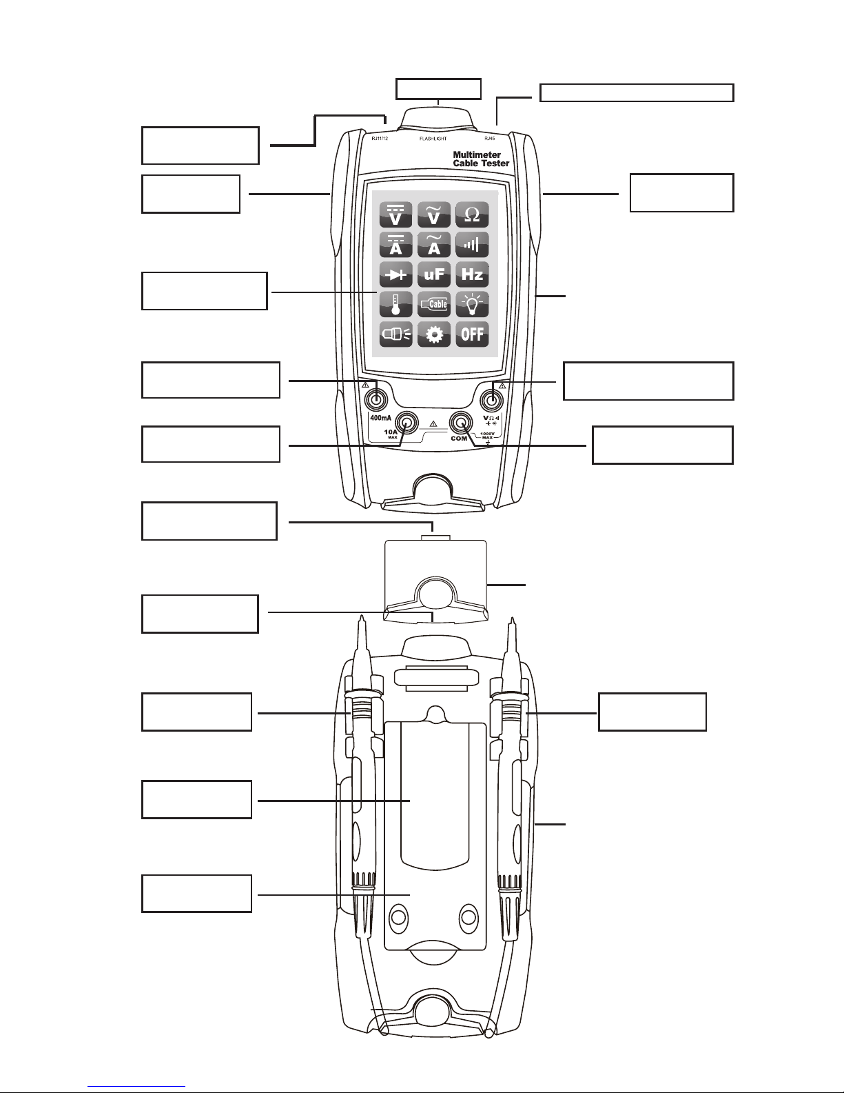
Overview .........................................................................................................
●Consist ........................................................................................................
●List of Devices ............................................................................................
Starting and Using .........................................................................................
Main Functions Menu and Using ..................................................................
●Measuring DC Voltage ................................................................................
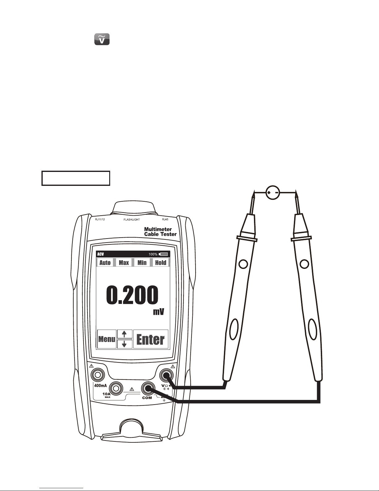
●Measuring AC Voltage ................................................................................
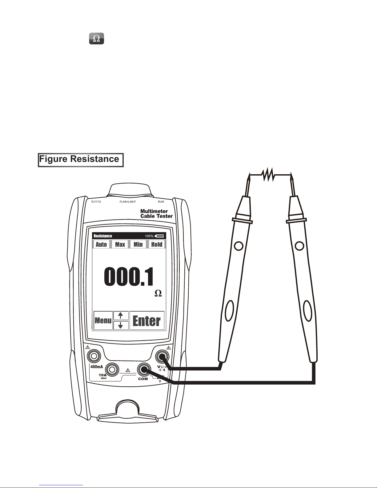
●Measuring Resistance ................................................................................
●Measuring DC Current ................................................................................
●Measuring AC Current ................................................................................
●Testing for Continuity .................................................................................
●Testing Diodes .............................................................................................
●Measuring Capacitance...............................................................................
●Measuring Frequency..................................................................................
●Measuring Temperature ..............................................................................
●Cables Tester ...............................................................................................
●Cable Link Test .......................................................................................
●Cable Length Measure ..........................................................................
●Cable Trace along signals of Toner Output .........................................
●Memo Function.......................................................................................
●Figure Cable Tester How to Install (LAN) (TEL) ..................................
●Figure Cable Tester How to Install (COAX) .........................................
●Backlight ......................................................................................................
●Lighting ........................................................................................................
●System Functions Setting ..........................................................................
●Buzzer Setting ........................................................................................
●Power Sleep ............................................................................................
●Unit for Length .......................................................................................
●Users Length ..........................................................................................
●Language for Menu ................................................................................
●Turn OFF the TCT-910 .................................................................................
Cleaning ..........................................................................................................
Replacing the Fuses ......................................................................................
Battery Power Charging ................................................................................
Specications .................................................................................................
Date of Edition ................................................................................................
3
3
4
4
4
5
6
8
8
8
9
10
11
12
13
14
15
16
17
18
20
21
22
23
26
27
28
28
29
29
30
30
31
32
33
34
34
34
35
36

3
Feature :
● The Unique and Smart Meter Design
● 3.5" TFT-LCD with Touch Panel
● Rechargeable
● Flashlight
● Shock Absorbable
Description :
● The Unique and Smart Meter Design
TCT-910 is the Unique and Smart design in the world by 3.5” TFT-LCD with Touch Panel.
● 3.5" TFT-LCD with Touch Panel
● 3.5" TFT-LCD (320*240)dots Colors with (Back Light + Touch Panel).
● TFT-LCD with Touch Panel for Display the Contents and Enter what function will you wanted.
● Keyboard less to select the operating function by touch the function pattern on the LCD.
● DMMs (Multi-Meter) Function
● High Class ADC with 14bit ADC (High Resolution of ADC)
● Multi-Meter items as below:
Voltage : AC, DC (0 ~ 600 V) Current : AC, DC (0 ~ 10 A)
OHM : 0 ~ 40 MΩ Capacitance : 1nF ~ 100 uF
Continuity : 0 ~ 400 Ω ; beeps at < 25 Ω Frequency : 0 ~ 99.99 KHz
Temperature : (-20 ~ +250 ˚C), (-4 ~ +482 ˚F)
Diode Test : 0 ~ 2.4V (Forward Bias)
● Cable Testers Function
● Cables Feature is Variant so you can ODM us for to do your Cables Test.
● Maybe TCT-910 do Cable test is not perfect for your expect,
Because Cable are many different kinds in the Market,
So that our database will been building continually…
● Has been test in our Lab which Base on (CAT.5e FTP) Cable Length (1~300) Meter.
● Cable Tester able to identify the condition as below list:
LAN Cable with (RJ-45) : (Pass, Open, Short, Cross, Split)
TEL Cable with (RJ-11/12) : (Pass, Open, Short, Cross)
Coax Cable with (F/BNC) : (Pass, Open, Short)
● Cable Tester able to Measure the Length of Cables as below list:
LAN Cable Length Range of measurement: More than (300 Meters)(1,000 Feet).
Coax Cable Length Range of measurement: More than (300 Meters)(1,000 Feet).
● Rechargeable
● Rechargeable Battery(3.7V, 2700mAh) inside that is Convenient for using.
● Standard Micro-USB Jack for Power(DC 5V) Input to Charge the Inside Battery.
● Flashlight
● Employ the White color with High Light LED for Lighting.
● Shock Absorbable
● Structures are designed to avoid breakdown that impact force from anyway or drop down
accidentally.
● Auto Power OFF
● Auto Power OFF function for power save that (Timers) are many Kinds Setting for Auto
Power OFF.

4
Safety Compliances
● IEC 61010 to 1000 V Measurement Category III, 600 V Measurement Category IV
Certications
● Rohs, CE, ETL
Overview
● Picture of Prole
V
~
A
~
uF Hz
Cable
V
A
OFF

5
● Consist
● Main Body
● RJ45 Port
Data cable, ethernet cable, 8-wire cable, 4 twisted pair cable, Cat5, Cat5e, Cat6, Cat7.
● RJ11/12 Port
Phone cable, POTS (plain old telephone service) cable, 4-wire cable, 6-wire cable,
2 twisted pair cable, 3 twisted pair cable, Cat3.
● Self-Storing Remote
● RJ45 Port
Data cable, ethernet cable, 8-wire cable, 4 twisted pair cable, Cat5, Cat5e, Cat6, Cat7.
● RJ11/12 Port
Phone cable, POTS (plain old telephone service) cable, 4-wire cable, 6-wire cable,
2 twisted pair cable, 3 twisted pair cable, Cat3.
● Accessory
● Probe Cable (DMMs)
(Red Probe lead) *1 , (Black Probe lead) *1 , For DMMs(V,A,R,...) Measuring.
● Kits of Coax Port * 2
(RJ45 Port to F-Connector Port) Video cable, coaxial cable, RG6 cable, RG59 cable.
● Kits of BNC Port * 2
(RJ45 Port to BNC Port) Video cable, coaxial cable, RG6 cable, RG59 cable.
● Kits of USB Port * 2 (Option)
(RJ45 Port to USB-Male)*1, (RJ45 Port to USB-Female)*1, For USB 2.0 Type A cable.
● Sensor of Temperature
K-Type Sensor for the surface Temperature of objects Measuring.
● Power Adaptor
AC(100V ~ 240V) to DC(5V, 1A)(USB-A Type)
● Power Cable
(USB-A Type) to (Micro-USB)
● Figure of Consist of TCT-910
ALL-IN-ONE DMM
& CABLE TESTERS
Power Adaptor
Power Cable
Main Unit
RJ45 to
F
Adaptor
Probe Cable (DMMs)
K-Type Sensor
(Temperature)
RJ45 to
BNC
Adaptor
RJ45 to
USB-AM
Adaptor
RJ45 to
USB-AF
Adaptor
Remote Unit

6
● List of Devices
( 1 ) Micro-USB Port for Battery Power Charging.
( 2 ) Power ON Button.
(Unique & Strong structure Tact Switch)(Push it for Power ON to use)
( 3 ) TFT-LCD with Touch Panel. (3.5 Inch TFT LCD with Resistance Touch Panel)
( 4 ) Lighting. (Using the 0.5W Ultra Bright LED with Focus Plastic Glass)
(For Lighting when working in dark area to avoid dangerous even occur)
( 5 ) RJ45 Port of Main Body.
( 6 ) RJ11/12 Port of Main Body.
( 7 ) Remote Unit. (With Both RJ45 and RJ11/12 Port)
( 8 ) Slot of Probe(+) for 400mA Measure.
( 9 ) Slot of Probe(+) for 10A Measure.
( 10 ) Slot of Probe(COM) for DMMs (Volt, Amp, Res, Diode, Cap, Freq, Temp...) Measure.
( 11 ) Slot of Probe(+) for DMMs (except Amp)(Volt, Res, Diode, Cap, Freq, Temp...)
Measure.
( 12 ) RJ45 Port of Remote Unit.
( 13 ) RJ11/12 Port of Remote Unit.
( 14 ) Docking of Probe(+)(Red)
( 15 ) Docking of Probe(-)(Black)
( 16 ) Cover of Battery.
( Remove this Cover for Renew Li-Ion Battery
when the current Battery is life time Out ).
( 17 ) Stander of Main Unit.
( For Easy to watch by the Stander be pulled off and standing
when Measuring fixture of objects ).

7
● Figure of (Front, Black) View
● Lighting
● RJ11/12 Port
of Main Unit
● RJ45 Port of Main Unit
● Power ON
Button
● RJ45 Port of
Remote Unit
● RJ11/12 Port of
Remote Unit
● TFT-LCD with
Touch Panel
● Docking of
Probe
( + )
● Cover of
Battery
● Stander of
Main Unit
● Slot of Probe(+)
(10A)
● Slot of Probe(+)
(400mA)
● Slot of Probe (+)
DMMs(except Amp.)
● Slot of Probe (-)
DMMs(V,A,R,...)
● Remote Unit
● Main Unit
● Main Unit
● Micro-USB
Port
●
Docking of
Probe ( - )
( 6 )
( 1 )
( 2 )
( 3 )
( 8 )
( 4 )
( 9 )
( 5 )
( 13 )
( 11 )
( 10 )
( 12 )
( 7 )
( 14 )
( 15 )
( 16 )
( 17 )

8
● Starting and Using:
●Please Use the Multi-Meter & Cable Tester
When it is not Power Charging to Battery from Micro-USB Jack…
● Please to Remove all Test (Probe) Leads from any Target of Measuring Before
1). The TCT-910 is System Power OFF.
2). Entry done that you wanted DMM Functions to Measure
3). Will to Change any Functions by touch menu on LCD Display of TCT-910.
Otherwise that should been Damage the TCT-910.
● Be Carefully Take (Probe) Leads to Probe Targets,
That are must to be met with DMMs Functions has been you setting.
● Push the Power ON Bottom on the left side for Starting the TCT-910.
● Main Functions Menu and Using:
● Measuring DC Voltage
● Touch the Icon of Root Menu on the LCM, To Launching the function of Measuring
DC Voltage.
● Set up your TCT-910 to Measuring DC Voltage as shown in Figure DCV.
● Probe the test points and read the display.
● Touch the ‘Menu’ Icon of DCV Measurement on the LCM, to back Root Menu.
Voltage source
Figure DCV
DC

9
AC
Voltage source
● Measuring AC Voltage
● Touch the Icon of Root Menu on the LCM, To Launching the function of Measuring
AC Voltage.
● Set up your TCT-910 to Measuring AC Voltage as shown in Figure ACV.
● Probe the test points and read the display.
● Touch the ‘Menu’ Icon of ACV Measurement on the LCM, to back Root Menu.
Figure ACV

10
● Measuring Resistance
● Touch the Icon of Root Menu on the LCM, To Launching the function of Measuring
Resistance.
● Set up your TCT-910 to Measuring Resistance as shown in Figure Resistance.
● Probe the test points and read the display.
● Touch the ‘Menu’ Icon of OHM Measurement on the LCM, to back Root Menu.
Resistor
Figure Resistance

11
DC DC
LOAD LOAD
Voltage sourceVoltage source
Figure DCA Large Current. Figure DCA Light Current.
● Measuring DC Current
● Touch the Icon of Root Menu on the LCM, To Launching the function of Measuring
DC Current.
● Set up your TCT-910 to Measuring DC Current as shown in Figure DCA Large Current.
When you want to Measuring DC Current are more than 280mA.
Then touch the ‘Enter’ Icon of DCA Measurement on the LCM, to swap DCA Unit to ‘A’ .
● Set up your TCT-910 to Measuring DC Current as shown in Figure DCA Light Current.
When you want to Measuring DC Current are less than 280mA.
Then touch the ‘Enter’ Icon of DCA Measurement on the LCM, to swap DCA Unit to ‘mA’ .
● Probe the test points and read the display.
● Touch the ‘Menu’ Icon of DCA Measurement on the LCM, to back Root Menu.

12
AC AC
LOAD LOAD
Voltage sourceVoltage source
Figure ACA Large Current. Figure ACA Light Current.
● Measuring AC Current
●Extra Must buy a kit of (ACA Converter) for this function to measuring (AC Current).
● Touch the Icon of Root Menu on the LCM, To Launching the function of Measuring
AC Current.
● Set up your TCT-910 to Measuring AC Current as shown in Figure ACA Large Current.
When you want to Measuring AC Current are more than 280mA.
Then touch the ‘Enter’ Icon of ACA Measurement on the LCM, to swap ACA Unit to ‘A’ .
● Set up your TCT-910 to Measuring AC Current as shown in Figure ACA Light Current.
When you want to Measuring AC Current are less than 280mA.
Then touch the ‘Enter’ Icon of ACA Measurement on the LCM, to swap ACA Unit to ‘mA’ .
● Probe the test points and read the display.
● Touch the ‘Menu’ Icon of ACA Measurement on the LCM, to back Root Menu.

13
Figure Continuity
ON
Closed
● Testing for Continuity
● Touch the Icon of Root Menu on the LCM, To Launching the function of Testing for
Continuity.
● Set up your TCT-910 to Testing for Continuity as shown in Figure Continuity.
● Probe the test points and read the display.
● Touch the ‘Menu’ Icon of Continuity Test on the LCM, to back Root Menu.
OFF
Open

14
● Testing Diodes
● Touch the Icon of Root Menu on the LCM, To Launching the function of Testing
Diodes.
● Set up your TCT-910 to Testing Diodes as shown in Figure Diode.
● Probe the test points and read the display.
● Touch the ‘Menu’ Icon of Diode Test on the LCM, to back Root Menu.
Figure Diode Forward bias diode

15
● Measuring Capacitance
● Touch the Icon of Root Menu on the LCM, To Launching the function of Measuring
Capacitance.
● Set up your TCT-910 to Measuring Capacitance as shown in Figure Capacitance.
● Probe the test points and read the display.
● Touch the ‘Menu’ Icon of Capacitance Measurement on the LCM, to back Root Menu.
Figure Capacitance. Capacitance.
Menu Enter
100%
Capacitance
0.235
uF
AutoM ax Min Hold

16
● Measuring Frequency
● Touch the Icon of Root Menu on the LCM, To Launching the function of Measuring
Frequency.
● Set up your TCT-910 to Measuring Frequency as shown in Figure Frequency.
● Probe the test points and read the display.
● Touch the ‘Menu’ Icon of Frequency Measurement on the LCM, to back Root Menu.
Figure Frequency
Frequency Source

17
Figure Temperature
● Measuring Temperature
● Touch the Icon of Root Menu on the LCM, To Launching the function of Measuring
Temperature.
● Set up your TCT-910 to Measuring Temperature as shown in Figure Temperature.
● Probe the test points and read the display.
● Touch the ‘Menu’ Icon of Temperature Measurement on the LCM, to back Root Menu.

18
● Cables Tester
● Touch the Icon of Root Menu on the LCM,
To Launching the function of Cable Tester.
● Setup your TCT-910 to Cable Tester
As shown in ( Page 26 )「Figure Cable Tester How to Install (LAN)(TEL) 」.
As shown in ( Page 27 )「Figure Cable Tester How to Install (COAX) 」.
● Using the Terminator with the Main Unit to do Cables Test....
● Choice the Kind of Cables
● Touch the ‘Cable’ Icon of Cable Tester Menu on the LCM,
To Launch the function of Cable Kinds choice.
● Touch the ‘UP’ or ‘Down’ Icon of Cable Tester on the LCM,
To select the Cable Kinds which one of ten(as below items)
{(Fig 3) (Fig 4) (Fig 5) (Fig 6) (Fig 7) (Fig 8) (Fig 9) (Fig 10) (Fig 11) (Fig 12)}
● Touch the ‘Enter’ Icon of Cable Tester on the LCM,
To decide the choice which one Kind of Cable after you are selected.
Note.
LAN Cable: (Users) (CAT.5) (CAT.5e) (CAT.6) (CAT.7) → as Fig 3~7
TEL Cable : (TEL 2P) (TEL 4P) (TEL 6P) → as Fig 8~10
Coax Cable: (Coax) → as Fig 11
USB Cable: (USB.A) → as Fig 12
Fig 3
Fig 2
Fig 1
Fig 4
Users
Users Users

19
Fig 7
Fig 10
Fig 12
Fig 5
Fig 8
Fig 11
Fig 6
Fig 9

20
● Cable Link Test
● Choice the Kind of Cables before do this (Cable Link Test) function.
● Choice the Mode of Cable Tester:
● Touch the ‘Mode’ Icon of Cable Tester Menu on the LCM, To Launch the function of Mode
(Cable Tester) choice.
● Touch the ‘UP’ or ‘Down’ Icon of Cable Tester on the LCM, To select the Mode of Cable
Tester which one of three(Link, Length, Toner), Here select the Mode is Link from the
three(Link, Length, Toner)
● Touch the ‘Enter’ Icon of Cable Tester on the LCM,
To decide the choice is Link Test.
● Execute the Link Test of Cables:
● Touch the ‘Enter’ Icon of Cable Tester on the LCM, To Execute the Linking Test of Cables
● You will understand what the status (PASS, OPEN, SHORT, CROSS, SPLIT) is of
Cables, After you do the Linking Test of Cables. (Please refer as below Fig...)
PASS
FAIL
FAIL
Table of contents