manuals.online logo
Brands
  1. Home
  2. •
  3. Brands
  4. •
  5. Bacharach
  6. •
  7. Test Equipment
  8. •
  9. Bacharach Model 105 User manual

Bacharach Model 105 User manual

COMBUSTION EFFICIENCY • COMBUSTION SAFETY • E N V I R O N M E N TA L M E A S UREMENTS
Since the 1930’s, Bacharach has been the global leader in the manufacture of portable combustion test-
ing analyzers and environmental monitors. Beginning with the introduction of our low cost CO2Fyrite®
Indicator Kit in 1935, Bacharach engineers have pioneered the state of the art combustion instrumenta-
tion. With over 90 years of instrumentation manufacturing and applications experience, Bacharach continues
to develop the most comprehensive, accurate and easy to use combustion and environmental testing instru-
mentation available. Our dedication to providing high quality instrumentation, backed up by the best customer
support and service departments in the industry, has never been greater. Our worldwide distribution, repair,
and service network has allowed Bacharach to maintain our leadership position in combustion analysis for over
six decades. Our commitment to the research, design and engineering of new, leading edge combustion and
environmental instrumentation will allow us to maintain our leadership position well into the 21st century.
B A C H A R A C H . T H E M E A S U R A B L E D I F F E R E N C E .
M O N O X O R ®I I
Hand-held CO Analyzer
On board electronics quickly and accurately
measure and display ppm levels of CO in
stack gas and room air. Also available in a
family of toxic and oxygen analyzers: NOX,
SO2, CO and oxygen.
P C A®
Portable Combustion Analyzer
Fast, accurate and easy CO safety
and efficiency test in a rugged and
reliable electronic instrument.
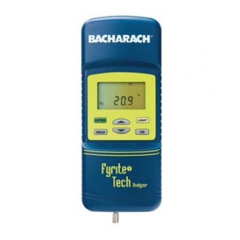
F Y R I T E ®P R O
Combustion Analyzer
An all-in-one instrument providing quick and
accurate information to conduct a combustion
test on residential combustion appliances.
MODEL 300 NSX
Combustion & Environmental Analyzer
Long a standard in the industry for electron-
ic measurement of combustion efficiency,
the Model 300 now also measures, displays,
and outputs ppm NOXand ppm SO2.
L E A K AT O R ®1 0
Leak Detector
Inexpensive instrument to quickly and
easily locate a variety of gas leaks.
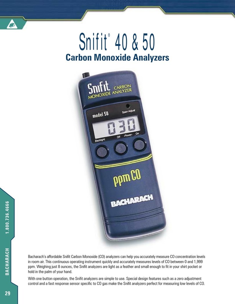
S N I F I T ®5 0
Hand-held CO2Analyzer
Hand-held digital CO analyzer, elec-
tronically measures CO in room air.
Also Snifit 40 is available to be used
in conjunction with digital multimeter.
Bacharach has been providing advanced combustion analysis equipment and technical support to engineers,
HVAC contractors, and boiler maintenance specialists around the world for over ninety years. To be sure that we
are providing our customers with the tools that they need, we talk to our customers, we listen to our customers,
and we ask questions.
In the past only two important questions needed to be answered: Can I get better fuel efficiency? and Is the
equipment operating safely?
Today, you are faced with more complex questions than ever before, with a new question at the top of the
list: Will my combustion equipment meet environmental regulations?
There is no doubt that environmental legislation has changed the way we all must evaluate combustion efficiency
and safety. As the leading manufacturer of electronic and mechanical combustion testing instrumentation, Bacharach has
developed this catalog to help you to answer many of the demanding technical questions which you face every day.
The questions answered here are the questions that we have received from professionals like yourself. The charts and
graphs have been designed to make your job easier. We have attempted to answer every question as thoroughly and clearly
as possible. If you have further questions about how Bacharach can help you to maintain efficient, safe, environmentally
sound combustion equipment operations, please call Bacharach at 412-963-2000 or send e-mail to: help@bacharach-inc.com.
COMBUSTION ANALYSIS
CA-1 What is combustion?
Combustion is the act or process of burning. For com-
bustion to occur, fuel, oxygen (air) and heat must be
present together.
CA-2 What is combustion efficiency?
Combustion efficiency is the calculation/measurement,
in percentage, of how well your equipment is burning a
specific fuel. Complete combustion efficiency (100%)
would extract all the energy available in the fuel.
However, 100% combustion efficiency is not realistically
achievable. Various combustion processes produce com-
bustion efficiencies from 0% to 95+%.
Combustion efficiency calculations assume complete
fuel combustion and are based on three factors:
1. The chemistry of the fuel.
2. The net temperature of the stack gases.
3. The percentage of oxygen or CO2by volume
after combustion.
If your calculation shows that your equipment is losing
25% of the heating value of the fuel through stack
losses, your equipment is running at 75% efficiency.
TABLE OF CONTENTS
Introduction 1
Combustion Analysis Q&A 1
Combustion Safety Q&A 5
Environmental Q&A 7
Technology Q&A 9
References 10
Glossary 11
Quality Plus Service 12
1
CA-3 I’ve always just eyeballed the flame. Is it
really important to do combustion testing?
Looking at the flame color, shape and stability
has been used as a “rule of thumb” for many
years but eyeballing will not allow you to opti-
mize the efficiency, safety, or environmental
compliance of your equipment. Just as doctors
make use of the most sophisticated instrumen-
tation possible when diagnosing their patients,
the best way to make sure that your equipment
is operating safely, and at maximum efficiency,
is by using combustion instrumentation.
CA-4 Are traditional instruments just as
good as continuous sampling electronic
instruments?
Traditional instruments will give you information
that is comparable in accuracy to electronic
instrumentation, but electronic instruments
have several advantages that can be very
important.
For example, many electronic instruments
monitor on a continuous basis, like a movie or
video camera. Traditional instruments are more
like a still camera that takes only one picture at a time.
With traditional instrumentation (the still camera), you
might miss the most important picture because your
camera is only capable of taking one picture at a time.
Because most electronic instruments sample on a con-
tinuous basis, like a video camera, you can see all the
information that will help you to evaluate the operating
condition of your equipment.
Electronic instruments will also do sampling and effi-
ciency calculations rapidly and automatically. Some
models will print out complete reports of test results or
transfer the stored data to a computer while adding
time and date information of the data collected.
CA-5 What do I have to do to measure for combus-
tion efficiency?
You only need to measure gas concentration
(oxygen or carbon dioxide) and temperature to
determine combustion efficiency.
Although other gases (NOX, CO, SO2) do not
significantly effect combustion efficiency,
these gases are an important safety and envi-
ronmental concern.
CA-6 Where should I take my sample?
The measurement for gases and temperature
should be taken at the same point. Make sure
that the sample point is before any draft
diverters and barometric damper so the gases are
not diluted and the temperature has not been
decreased by outside air. A proper sampling
location for a residential gas furnace
would be inside the heat exchanger tubes.
For residential and light commercial or
industrial equipment, use the following
guidelines:
Oil Burners - Locate the sampling hole at least six
inches upstream from the furnace side of the draft reg-
ulator and as close to the furnace breaching as possible.
Gas Burners - Locate the sampling hole at least six inch-
es upstream from the furnace side of the draft diverter
or hood, and as close to the furnace breaching as pos-
sible.
For Larger Equipment - Locate the sampling point
downstream from, and as close as is practically possible
to, the last heat exchange device (economizer, recuper-
ator, or similar device). This will insure that the net tem-
perature will provide an accurate indication of the effec-
tiveness of the exchangers.
2
Chart 1
COMBUSTION PROCESSES AND THEIR COMBUSTION EFFICIENCY RANGES
Process Typical Combustion
Efficiency Range
Home Fireplace 10-30%
Space Heater 50-82%
Commercial Gas Boiler 70-82%
Residential Gas Furnace with Atmospheric Burner “low efficiency”70-82%
Oil Burner Heating System 73-85%
Induced Draft Furnace “Medium Efficiency”74-82%
Boiler with Gas Powered Burner75-83%
Condensing Furnace (gas & oil) “High Efficiency”85-93%
CA-7 I know that O2, CO, CO2, temperature and
smoke can tell me a lot about combustion.
How do they all relate to efficiency?
Theoretically, peak fuel efficiency is achieved by “per-
fect” combustion, also called the Stoichiometric Mix
(see charts #2 and #3).
If it were possible to have perfect combustion, CO2
would be maximized and O2would be at, or close to,
zero in the flue gas stream. Because perfect combustion
is not practically possible, most combustion equipment
is set up to have a small percentage of excess O2pre-
sent. The lower the temperature for a given O2or CO2
reading, the higher is your combustion efficiency. This is
because less heat is lost up the stack.
In a Stoichiometric Mix, all the fuel and oxygen (O2)
present combines to generate only heat, water and car-
bon dioxide (CO2).
Smoke is the usual indicator of incomplete combustion
in oil burners. In addition to indicating poor combus-
tion, smoke can deposit soot on your heat exchangers
which will further reduce fuel efficiency; and smoke
coming out of the stack can be cause for air quality vio-
lation.
To give you a graphic illustration of how dramatically
smoke and soot can effect fuel combustion efficiency,
we have included chart #4. We have also included a
common fuel characteristics chart (chart #5) for several
of the common fuels used in combustion equipment.
CA-8 Is measuring draft important?
Draft measurement is important because draft controls
how rapidly the gases (O2, CO, CO2- and even fuel)
pass through the furnace and boiler.
3
Chart 2
THEORETICAL AIR CURVE/FUEL OIL
Chart 3
THEORETICAL AIR CURVE/NATURAL GAS
Chart 4
EFFECT OF SOOT ON FUEL CONSUMPTION
Chart 5
COMMON FUEL CHARACTERISTICS
(Complete Combustion) Higher
Heating Carbon Hydrogen Ultimate Moisture
Value
NATURAL GAS 21,830 BTU/lb. 69.4% 22.5% 11.7% -
KEROSENE 19,942 BTU/lb. 86.5% 13.2% 15.12% -
137,000 BTU/gal.
PROPANE 21,573 BTU/lb. 81.6% 18.4% 13.8% -
FUEL OIL NO.2 18,993 BTU/lb. 87.3% 12.5% 15.7% -
137,080 BTU/gal.
FUEL OIL NO.6 18,126 BTU/lb. 88.5% 9.3% 16.7% -
153,120 BTU/gal.
ANTHRACITE COAL 12,680 BTU/lb. 80.6% 2.4% 19.9% -
BITUMINOUS COAL 14,030 BTU/lb. 80.1% 5.0% 18.5% -
BAGASSE 8,200 BTU/lb. 45.0% 6.4% 20.3% 50.0%
WOOD 8,800 BTU/lb. 50.0% 6.5% 20.0% 10.0%
(10%moisture)
Typical draft overfire measurements* (0.02 inches H2O)
and flue draft measurements** (0.04 to 0.06 inches
H2O) insure that there is continuous negative pressure
in the combustion system. Excess draft will increase
your stack temperature and decrease your combustion
efficiency.
It is important to measure draft on the chimney side, well
downstream from a draft diverter. This measurement will
tell you if there is sufficient draft to move the flue gases
up the chimney and vent them to the outside air.
CA-9 Will frequent testing increase my fuel
savings?
The most basic and simplest way to save fuel is by
adjusting the combustion process to obtain optimum
combustion efficiency. Improving combustion efficiency
will ultimately save on fuel. Every situation is different,
but frequent testing to improve combustion efficiency
will maintain fuel efficiency.
Additionally, frequent testing will give you a “running
history” of the maximum operating capability of each
piece of combustion equipment that you test. By using
this history to establish a benchmark, you can maintain
your equipment at peak efficiency.
Although some combustion experts test on a weekly
basis, many other experts test only three or four times
per year. Annual testing is the minimum acceptable
level of testing that must be done on small furnaces.
CA-10 As my combustion efficiency improves, how
do I calculate my fuel savings?
First you have to determine the change in efficiency
with instrumentation. Then you can use chart #6 to cal-
culate your fuel savings.
CA-11 How much does temperature and CO2affect
efficiency?
A decrease in stack temperature of 40°F (20°C) will
result in increased combustion efficiency of 1-2%. An
increase of 1% in CO2will increase combustion effi-
ciency by 1/2% to 1%.
CA-12 What should my O2, CO2and CO be on the
common fuels?
Chart #7 (pg. 5) will give you a guideline for common
fuels and percentage of gas, but you should also check
the manufacturer’s recommendations for excess air.
Carbon Monoxide (CO) should always be minimized.
CA-13 How do I run a combustion test on a high
efficiency furnace?
Testing of a high efficiency furnace is not much different
from the testing of a natural draft furnace. The biggest
differences are the sampling points (see chart #7, pg. 5)
and the need to be able to calculate higher efficiencies:
up to 99.9%.
CA-14 Is is important to measure smoke in oil fired
furnaces?
Yes, because smoke is a primary sign of incomplete
combustion and fouling, it is very important. Using an
authentic smoke spot testing instrument will determine
oil burner condition and operating efficiency and safety
(see chart #8, pg.5). However, smoke spot testing of
modern oil burning equipment may not indicate the
presence of CO. Because smoke and CO may coexist,
or exist independently, and both affect combustion effi-
ciency, both smoke and CO tests are necessary.
4
Chart 6
SAVINGS FOR EVERY $100 FUEL COSTS BY INCREASE OF COMBUSTION EFFICIENCY
Assuming constant radiation and other unaccounted-for losses
From an original To an increased
efficiency of… combustion efficiency of…
55% 60% 65% 70% 75% 80% 85% 90% 95%
50% $9.10 $16.10 $23.10 $28.60 $33.30 $37.50 $41.20 $44.40 $47.40
55% - 8.30 15.40 21.50 26.70 31.20 35.30 38.90 42.10
60% - - 7.70 14.30 20.00 25.00 29.40 33.30 37.80
65% - - - 7.10 13.30 18.80 23.50 27.80 31.60
70% - - - - 6.70 12.50 17.60 22.20 26.30
75% - - - - - 6.30 11.80 16.70 21.10
80% - - - - - - 5.90 11.10 15.80
85% - - - - - - - 5.60 10.50
90% - - - - - - - - 5.30
* Always be sure to follow manufacturer’s recommendations.
** 1 inch H2O = 2.5 hla
CA-15 In an oil fired furnace, when do I measure
smoke?
Smoke is best measured when the burners have
stabilized, normally one minute after ignition for small
combustion equipment.
CA-16 Can oil furnaces and boilers produce CO?
Oil burners, and any other piece of combustion equip-
ment, will produce CO (carbon monoxide) when there
is not sufficient mixing of O2and fuel for complete
combustion.
COMBUSTION SAFETY
CS-1 What is Carbon Monoxide (CO) and where is
it found?
Carbon Monoxide (CO) is a highly toxic, lighter than air
gas which is most often found in an area surrounding a
combustion source (a furnace, boiler or space heater)
where there is insufficient oxygen to allow for complete
combustion of the fuel in use.
Carbon Monoxide is very dangerous because it is color-
less, odorless, tasteless, and non-irritating. It is virtually
impossible to detect Carbon Monoxide without a test-
ing instrument.
Carbon Monoxide is also flammable and burns in air
with a bright blue flame.
CS-2 How dangerous is Carbon Monoxide?
Carbon Monoxide is very dangerous: over 800 people
die each year from CO poisoning in the United States.
Most of us know that high levels of CO are harmful.
What is less well known is that CO is a cumulative poi-
son. CO can slowly build up in the bloodstream. In the
bloodstream CO combines with blood hemoglobin and
replaces the oxygen in the bloodstream until there is
too little oxygen in the bloodstream to support life.
Some of the danger signs of CO poisoning are:
headaches, dizziness, tiredness, and nausea. Frequently,
CO poisoning is confused with other diseases because
the symptoms are similar to flu or the common cold.
Death from CO poisoning can happen suddenly.
Victims of CO poisoning are overcome and helpless
before they realize that any danger exists.
We have included a chart which illustrates the effects of
CO at various PPM and hours of exposure (chart #9).
5
Chart 7
RELATIONSHIP BETWEEN O2, CO2AND EXCESS AIR
Chart 9
EFFECTS OF CARBON MONOXIDE
Chart 8
BURNER PERFORMANCE
Smoke Scale
Reading
1Excellent – Little, if any, sooting of furnace or boiler
surfaces.
2Good – May be slight sooting with some types of furnace
or boiler but little increase in flue gas temperature.
3Fair – Substantial sooting with some types of furnace or
boiler and require cleaning more than once a year on
most types of furnace or boiler.
4Poor – This is a borderline smoke-some units may soot
only moderately, others may soot rapidly.
5Very Poor – Heavy sooting in all cases- may require
cleaning several times during the season.
6Extremely Poor – Severe and rapid sooting-may result in
damage to stack control and reduce overfire draft to
danger point.
CS-3 How can I prevent Carbon Monoxide
poisoning?
The best way to prevent Carbon Monoxide poisoning is
to make sure that your combustion equipment is func-
tioning properly. Combustion air openings (vents, flues,
exhausts and ducts) must be kept open, clean and free
of blockages such as dirt, dust, lint and trash.
Never obstruct a draft hood, wind cap or exhaust vent
on any combustion appliance. Don’t store anything
against or near the equipment that could restrict the air
flow.
In a private home or apartment, a roaring fireplace is
always nice on a cold day. But when combined with a
marginal air flow to the furnace room, the fireplace
might draw enough air to starve the furnace, producing
a potentially hazardous backdraft of Carbon Monoxide
in the living areas.
The best way to prevent CO poisoning is to be con-
stantly aware that CO is a deadly gas: testing is the
only way to detect its presence.
CS-4 What are the best ways to test for Carbon
Monoxide?
Because CO is colorless, tasteless, odorless and non-irri-
tating, the only way to detect its presence is to use a
testing device or instrument.
Electrochemical sensors make detection much faster
and easier and allow you to find fluctuating CO levels
which would be difficult or impossible to measure any
other way: changes as small as 1 ppm can be detected.
There are two types of chemical stain length tubes that
may be used. Indicating tubes give you a go/no go
reading and detect a wide range of CO concentrations.
Detector tubes allow you to make more accurate and
refined measurements which give you concentration
measurement in the 0-5,000 ppm range.
CS-5 If I do find dangerous levels of Carbon
Monoxide, how do I get rid of it?
If the level of CO is dangerous, evacuate the area
immediately and provide as much ventilation of fresh air
as possible to the area where the CO is concentrated.
After determining, with instrumentation, that the CO
level has been reduced to a safe level, use your instru-
mentation to find the source of the CO and correct the
conditions which caused the CO formation. (Some local
codes may require that you immediately shut down the
equipment and notify the owner/operator).
CS-6 What are the federal safety standards for
Carbon Monoxide?
The Occupational Safety and Health Administration
(OSHA) has set a maximum limit of 50 ppm for eight
hours exposure in the workplace. In some states this
limit may be lower.
The Environmental Protection Agency (EPA) and the
American Gas Association (AGA) have set a maximum
allowable of 400 ppm (on a CO air free basis) in flue gas.
The American Society of Heating, Refrigeration and Air
Conditioning Engineers (ASHRAE) recommends 9 ppm
as the maximum acceptable level of CO in a residential
setting (ASHRAE Ventilation Standard 62-89).
CS-7 Why is a cracked heat exchanger dangerous?
In a warm air furnace, a cracked heat exchanger can
cause a build-up of toxic gases, including CO, which
would be distributed by the blower into the living or
working area causing sickness or death.
6
Chart 10
CO CONCENTRATIONS & SYMPTOMS DEVELOPED
Concentrations Inhalation time and
of CO in the air toxic symptoms developed
9 ppm (0.0009%) The maximum allowable concentration for
short term exposure in a living area,
according to ASHRAE.
50 ppm (0.0050%) The maximum allowable concentration for
continuous exposure in any 8-hour period,
according to federal law
200 ppm (0.02%) Slight headache, tiredness, dizziness,
nausea after 2-3 hours
400 ppm (0.04%) Frontal headaches within 1-2 hours, life-
threatening after 3 hours, also maximum
parts per million in flue gas (on an air free
basis), according to EPA and AGA
800 ppm (0.08%) Dizziness, nausea and convulsions within
45 minutes. Unconsciousness within
2 hours. Death within 2-3 hours.
1,600 ppm (0.16%) Headache, dizziness and nausea within
20 minutes. Death within 1 hour.
3,200 ppm (0.32%) Headache, dizziness and nausea within
5-10 minutes. Death within 30 minutes.
6,400 ppm (0.64%) Headache, dizziness and nausea within
1-2 minutes. Death within 10-15 minutes.
12,800 ppm (1.28%) Death within 1-3 minutes.
CS-8 How do I check for a cracked heat exchanger?
Visual inspection of the heat exchanger should always
be done first. It may not be possible with visual inspec-
tion alone to make sure that the heat exchanger has no
cracks or pinhole leaks caused by corrosion.
One sign of a cracked heat exchanger is a change of
oxygen concentration in the flue gases of greater than
1/2% oxygen, or a change in the carbon monoxide
level greater than 25 ppm. This change is measured by
comparing readings before and after the circulation
blower has turned on. For this test to be valid, CO lev-
els must be present in flue gas.
Although some cracks may be seen with visual inspec-
tion alone, the method described above can be used to
find “invisible” cracks or cracks that may expand as the
furnace heats up.
CS-9 What’s the relationship between indoor air
quality (IAQ) and combustion safety?
Good, efficient combustion is safe combustion: safe
combustion maintains good indoor air quality.
CS-10 What are the most common chimney
problems?
Simple blockages caused by birds nests, chimney dete-
rioration, soot build-up and other “natural” occur-
rences restrict the air flow through the combustion
equipment and can cause incomplete, inefficient com-
bustion which will produce dangerous levels of toxic
gases which could infiltrate the living/working area.
High levels of moisture in chimneys can cause the lining
materials to decompose, creating restrictions which
reduce the ability of the chimney to draw sufficient air
to assure efficient, safe combustion.
Performing draft measurements will allow you to be
sure that the chimney has vented flue gases to the out-
side air.
CS-11 How does inadequate ventilation increase the
hazard of CO?
Weathertight homes and increased use of exhaust fans
will create a negative pressure within a home.
Negative pressure conditions and blocked flue stacks
can result in combustion appliance backdraft into the
living areas.
Also, weathertight homes may have insufficient fresh
air to support complete combustion, producing CO.
E N V I R O N M E N TA L
EC-1 How important is it to measure NOX, SO2, and
CO for environmental compliance?
If your local regulatory authorities require measurement
of these gases, it is very important to comply. Non-
compliance (ignoring these gases) could result in fines,
penalties and eventually, the shutdown of your equip-
ment.
Air quality regulations vary from state-to-state and
from region-to-region.
Contact your EPA office or state environmental office
for the most current information about the specific
environmental regulations which affect you.
Because regulations change, and new regulations are
always being written into law, you should check at least
twice a year with the EPA and/or DER to make sure that
you are in compliance with current regulations.
EC-2 Is it difficult to convert ppm gas measure-
ments to other units of measurements?
Other units of measurement are used to determine the
weights of each of the pollutants for an amount of each
fuel burned. Sometimes regulations are written which
include these other units of measurement.
Chart #11 below, will allow you to easily convert ppm
to other units of measurement.
7
Chart 11
POLLUTANT CONVERSIONS
To convert from ppm to any of the units below, multiply ppm by
the number in the correct column and row.
Fuel Pollutant LB/MBTU MG/NM3 MG/KG G/GJ
NAT GAS CO 0.00078 1.249 12.647 0.338
NAT GAS NOX0.00129 2.053 20.788 0.556
NAT GAS SO20.00179 2.857 28.949 0.775
OIL (#2, #6) CO 0.00081 1.249 15.118 0.354
OIL (#2, #6) NOX0.00134 2.053 24.850 0.582
OIL (#2, #6) SO20.00186 2.857 34.605 0.811
COAL CO 0.00107 1.249 27.178 0.460
COAL NOX0.00167 2.053 42.418 0.718
COAL SO20.00233 2.857 59.1847 1.000
Definitions:
All numbers apply to values as corrected to 3% excess Oxygen (6% for coal)
and dry gas.
LB/MBTU: pounds of pollutants per Million BTU (British Thermal Unit)
MG/NM3: milligrams of pollutant per Normal cubic meter of gas sampled
MG/KG: milligrams of pollutant per Kilogram of fuel burned
G/GJ: grams of pollutant per GigaJoule (109Joule)
EC-3 What is the difference in NO and NO2in stack
gases?
Nitric oxide (NO) and Nitrogen Dioxide (NO2) are the
toxic gases which constitute NOX. All combustion
processes can produce NOX.
NOXemissions contribute to the formation of acids in
the earth’s lower atmosphere; these acids contribute to
the formation of acid rain.
Additionally, NOXand hydrocarbons can react with
sunlight to produce a potent respiratory irritant that is
commonly called smog.
NOXfrom combustion comes from three different
sources: thermal NOX, prompt NOXand fuel bound
NOX.
In boilers or furnaces which burn fuels low in nitrogen
(gas and light oils), thermal NOXpredominates. When
fossil fuels rich in nitrogen (heavy oils) are burned, high-
er concentrations of fuel NOXare generated.
Prompt NOXis a small amount of total NOXemissions
that occur during low temperature stages of combus-
tion.
Typically, Nitric Oxide (NO) comprises over 95% of the
NOXfound in stack gases. However, a significant
amount of NO converts to NO2in the atmosphere.
Because NO and NO2combine to form NOX, which
contributes to smog and acid rain, legislation to reduce
and control these emissions has become much tougher.
EC-4 Where do I get information about specific
environmental combustion regulations that
could affect my organization?
The best source of information is your local or regional
EPA and DER office. You can find them listed in the tele-
phone directory.
EC-5 What is the Clean Air Act and does it apply to
everyone with a furnace or boiler?
The Clean Air Act of 1970, including the amendments
made in 1990, is a federal law which was created to
reduce air pollution (smog), acid rain and other air pol-
lutants which have been identified as toxic emissions.
The Act itself is 868 pages in length and encompasses
virtually every conceivable form of air pollution, air pollu-
tion abatement programs and even requires that methods
used in testing, for example SO2, meet legislated criteria.
Some of the provisions of The Clean Air Act are:
-SO2emissions from utilities reduced by 50%.
- 189 toxic substances will be measured by peer
review.
- Five year federal operating permits to be issued.
- EPS continues to develop federal regulations to
assure compliance.
The 1990 amendments to the Federal Clean Air Act of
1970 have established a dramatically different air toxins
program.
This Act requires the EPA to establish operational and
monitoring guidelines for industrial and commercial
boilers and empowers state and local authorities to
enforce the regulations.
These new regulations will affect combustion processes
in facilities as diverse as large petrochemical plants and
small local schools; regulatory compliance will become
commonplace for nearly every industry, company and
institution.
Already the South Coast Air Quality Management
District (SCAQMD) in Southern California has developed
its own legislation that will enforce the EPA guidelines.
Rule 1146 requires that boilers over 2 million BTU per
hour in capacity operate with NOXemissions of less
than 40 ppm. To meet these stringent requirements,
routine testing of stack gases for NOXand other com-
bustion by-products is legislatively mandated in
Southern California. Using the SCAQMD as a model,
other states and regions are developing similar regula-
tory programs across the United States.
Internationally, the regulatory climate is becoming
much tougher. Germany has passed legislation which
mandates the NOXtesting of residential furnaces.
8
T E C H N O L O G Y
TC-1 I’ve always been able to get along by
eyeballing the flame. Why should I use a
mechanical or electronic instrument?
As amazing as the human eye is, it is not capable of per-
forming quantitative analysis of changing colors in
widely varying surroundings and situations.
The only quantifiable analysis that you can depend on
is achieved through the use of mechanical or electronic
instrumentation.
TC-2 If mechanical instruments will do the job why
should I use electronic instruments?
As mentioned in the combustion analysis section, elec-
tronic instrumentation has several other benefits which
are important.
The speed and accuracy of electronic instrumentation,
coupled with the convenience of a computer, allows
you to create hard copy reports which eliminates
tedious, time consuming and frequently inaccurate,
handwritten reports.
In our society, the increasing demand for pollution con-
trol and the increased possibility of severe fines or legal
actions has made all of us more aware of the need to be
able to demonstrate, in a tangible way, that we have
performed as professionals and have done everything
possible to insure environmental and safety compliance.
Electronic instrumentation combines higher levels of
accuracy with faster testing, and demonstrable hard copy
evidence of date, time and results of testing. This will
provide you the most accurate and most cost effective
way to assure that the information you need to perform
as a professional is always available and easy to retrieve.
In addition to continuous testing, many electronic
instruments will allow you to transfer and store infor-
mation in a computer. This information can be identi-
fied and logged to allow you to generate a “history” of
each individual piece of combustion equipment that
you test.
By referring to this “history,” you will have a solid ref-
erence point for the levels of fuel efficiency, safety, and
environmental compliance achievable for any boiler or
furnace that you test.
TC-3 What is the biggest difference between
mechanical and electronic instruments?
The most important difference is the elimination of
potential human error.
Electronic instruments simplify testing, eliminate the
need for interpretation of measurements, and perform
error free combustion calculations automatically.
TC-4 What are the advantages of using electronic
instruments for combustion testing?
In addition to the advantages which we have detailed
before, many service personnel have told us that the
advantages of using electronic instruments are: speed
and ease of use, automatic sampling, automatic calcu-
lations and automatic report generation.
Electronic instruments also provide individual displays of
O2, CO, NOX, etc., which allow immediate monitoring
and independent analysis of each adjustment as it is
made on a boiler or furnace.
TC-5 What type of sensors are used in electronic
instruments?
Although sensors are manufactured for specific gases
and have small but significant differences, the basic
concept for sensors used to measure carbon monoxide
(CO), nitric oxide (NO) and sulphur dioxide (SO2) are
very similar.
Electrochemical sensors are entirely contained within a
sealed plastic capsule or body. The major working ele-
ments are three coated electrodes (sensing, counter and
reference) and a small volume of an acid solution.
In use, the gases diffuse through a small orifice on the
sensing face of the sensor to the electrode surface and
cause a change in the measured gas, which initiates a
small electrical current.
The current, which is directly proportional to the con-
centration of gas being measured, is amplified and
scaled by the electronics. The value is then displayed or
is available for printing or downloading to the comput-
er, depending on the instrument being used.
Electrochemical oxygen sensors are manufactured and
operate in a slightly different way.
Oxygen sensors are also entirely contained within a
sealed plastic body which contains a consumable
counter electrode (usually lead), a sensing electrode and
a small volume of a base solution.
In use, oxygen diffuses through a membrane which
covers the face of the sensor, the gas contacts the sens-
ing electrode and the base solution and reacts at the
wet surface of the electrode. This reaction consumes
the counter electrode.
The chemical change in the counter electrode allows a
circuit in the instrument to measure a potential (volt-
age) between the sensing and counter electrodes. This
voltage is directly proportional to the concentration of
oxygen in the gas being sampled. The value is then dis-
played or is available for printing or downloading,
depending on the analyzer being used.
9
TC-6 How often do I have to calibrate my electronic
instruments?
Calibration consists of zeroing and spanning sensors.
The CO, NOXand SO2sensors are zeroed automatical-
ly in some instruments. Simultaneously, the oxygen sen-
sor is automatically spanned of 20.9 O2in air.
Most manufacturers recommend that calibration using
certified concentrations of test gases be done at least
every six months.
TC-7 How long do electrochemical sensors last?
Manufacturers’ warranties may be different, chart #12
below is a good indication of “average sensor life.”
TC-8 What is the easiest way to calculate combus-
tion efficiency?
The easiest way is to use a micro-processor based elec-
tronic instrument. Mechanical instruments and slide rule
calculations are equal in accuracy but less convenient.
TC-9 How do electronic instruments calculate CO2?
An equation is programmed into the analyzer which
calculates CO2from the oxygen and fuel measure-
ments.
By selecting a specific fuel from a preprogrammed
“menu” of fuels, and by sampling the flue gas, the
electronic instrument will automatically calculate and
display the CO2value.
R E F E R E N C E S
CSA International
8501 E. Pleasant Valley Road
Cleveland, OH 44131
(216) 524-4990
Bacharach, Inc.
625 Alpha Drive
Pittsburgh, PA 15238-2878
(412) 963-2000
Boiler Efficiency Institute
P.O. Box 2255
Auburn, AL 36831-2255
(334) 821-3095
Department of Energy and Environment
Brookhaven National Laboratory
Upton, NY 11973
(516) 344-7916
Columbia Gas
650 Washington Road
Pittsburgh, PA 15228
(412) 344-9800
Environmental Protection Agency (EPA)
Research Triangle Park
NC, 27711
(919) 541-5544
Department of Environmental Protection
400 Waterfront Drive
Pittsburgh, PA 15222-4745
(412) 442-4000
Peoples Natural Gas
625 Liberty Avenue
Pittsburgh, PA 15222-3197
(412) 471-5100
South Coast Air Quality Management District
21865 E. Copley Drive
Diamond Bar, CA 91765-4182
(909) 396-2000
Southern California Gas
555 West 5th Street
Los Angeles, CA 90013
(213) 244-1200
10
Chart 12
TYPICAL SENSOR LIFE
Sensor Gas Life
ELECTROCHEMICAL O2Oxygen 1 Year Plus
ELECTROCHEMICAL NO Nitric Oxide 2 Years Plus
ELECTROCHEMICAL NO2Nitrogen Dioxide 2 Years Plus
ELECTROCHEMICAL SO2Sulfur Dioxide 2 Years Plus
ELECTROCHEMICAL CO Carbon Monoxide 2 Years Plus
GLOSSARY OF TERMS
A.G.A.: American Gas Association
Air-Fuel Ratio: The ratio of weight or volume of
air to fuel.
Ambient Air: The atmosphere external to fur-
nace, appliance or process.
ASHRAE: American Society of Heating,
Refrigeration and Air
Conditioning Engineers
British Thermal The amount of heat required to
Unit: raise 1 pound of water 1°F.
Calibration: Comparison of an instrument of
lesser accuracy with another stan-
dard of known accuracy (calibra-
tion gas) to detect, correct and
adjust for instrument accuracy.
Calorie: The amount of heat required
to raise 1 gram of water 1°C.
Carbon Dioxide: A colorless gas, heavier than air,
formed by the complete combus-
tion of carbon.
CO: The chemical symbol for carbon
monoxide.
CO2:The chemical symbol for carbon
dioxide.
Combustion A fuel-burning (oil, gas, coal or
Appliance: wood) device such as a range,
furnace, boiler or water heater.
Combustion Air: The air supplied for combustion
of the fuel.
Combustion The portion of the heating or
Chamber: process equipment where fuel is
burned.
Dampers: Controls that vary air flow through
an air outlet, inlet or duct.
DOE: Department of Energy
Environmental Conditions other than indoor air
Factors: contaminants that cause stress,
discomfort and/or health problems
(e.g. humidity extremes, drafts
and lack of air circulation).
EPA: Environmental Protection Agency
Excess Air: Air supplied for combustion in
excess of that theoretically
required for complete oxidation
of the fuel.
Flue: A passageway for conveying
combustion products to the
outside air.
Flue Gases: Gaseous products of combustion.
Heat Exchanger: A device that transfers heat from
one system to another, such as in
a warm air furnace.
IAQ: Indoor Air Quality
Incomplete Combustion in which fuel is only
Combustion: partially burned and is capable of
being further burned under proper
conditions of temperature and air.
Indoor Air: The air that occupies the space
within the interior of a house or
other buildings.
Makeup Air: Outdoor air supplied into a build-
ing to compensate for air which is
exhausted by combustion appli-
ances or other devices such as
exhaust fans.
NO: The chemical symbol for
Nitric Oxide.
NO2:The chemical symbol for
Nitrogen Dioxide.
OSHA: Occupational Safety and Health
Administration
Orsat: A gas analysis apparatus in which
the CO2or O2gaseous constituents
are measured by absorption in
separate chemical solutions.
Oxides of Nitrogen The sum of NO (Nitric Oxide)
(NOX): and NO2(Nitrogen Dioxide).
Perfect Combustion The combining of the chemically
(Stoichiometric): correct proportions of fuel and air
in combustion so that the fuel
and oxygen are both totally
consumed.
Plenums: Enclosures for the collection of
air at the termination or origin
of duct systems.
Primary Air: Air mixed with the fuel inside
the burners.
Secondary Air: Air for combustion supplied
to the outside of the flame to
supplement the primary air.
SO2:The chemical symbol for sulfur
dioxide.
11
S A L E S A N D S E R V I C E C E N T E R S
Bacharach Sales/Service Center
7281 Garden Grove Blvd., Suite H
Garden Grove, CA 92841
Ph: 714-895-0050
Fax: 714-895-7950
Email: [email protected]
Bacharach Sales/Service Center
8618 Louisiana Place
Merillville, IN 46410
Ph: 219-736-6178
Fax: 219-736-6269
Email: [email protected]
Bacharach Sales/Service Center
7300 Industrial Park
Rte. 130, Bldg. 22
Pennsauken, NJ 08110
Ph: 856-665-6176
Fax: 856-665-6661
Email: [email protected]
Bacharach Sales/Service Center
621 Hunt Valley Circle
New Kensington, PA 15068
Ph: 856-665-6176
Fax: 856-665-6661
Email: [email protected]
Bacharach of Canada
250 Shields Court Unit #3
Markham, Ontario L3R 9W7 CANADA
Ph: 905-470-8985
Fax: 905-470-8963
Toll Free: 800-328-5217
Email: [email protected]
Bacharach de Mexico
Playa Regatas No. 473 Tercer Piso
Col. Militar Marte
Delegacion Iztacalco, 08830
Mexico D.F. Mexico
Ph: +52-555-634-7740
Fax: +52-555-634-7738
Email: [email protected]
Bacharach Europe
Sovereign House, Queensway
Royal Leamington Spa
Warwickshire CV31 3JR
United Kingdom
Ph: +44-1926-338111
Fax: +44-1926-338110
Email: [email protected]
B A C H A R A C H ’ S I N S T I T U T E O F
TECHNICAL TRAINING
As the global leader in combustion testing and envi-
ronmental monitoring instrumentation, Bacharach has
been developing, designing, engineering and manu-
facturing portable combustion and environmental
measurement instrumentation for almost a century.
Bacharach engineers and scientists have spent decades
developing instrumentation and procedures that help
assure combustion safety and support indoor air quality.
Now Bacharach’s trained specialists can share their
expertise with you through several technical training
seminars. Plus learn how to:
• Generate new business leads
• Retain existing customers
• Reduce liability
Who Should Attend?
Why Attend?
Each attendee who attends a four-hour course will
receive from Bacharach, a four course training manual
($90 value), four registered hours of instruction and
certicate of attendance. Additionally, each attendee
will gain access to the full line of Bacharach Services and
Departments, including Product, Sales and Marketing.
Our trainers will continue to work with attendees
requesting technical assistance via telephone or other
links. Attendees will also receive a newsletter periodically
from Bacharach, highlighting industry news and provid-
ing technical updates.
Call Bacharach’s Institute of Technical Training
today for more information at 1-800-736-4666.
For a schedule of the upcoming training
seminars in your area, please visit our website
at www.bacharach-inc.com.
12
• H VAC Service Technicians
& Contractors
• Weatherization Auditors
• Safety and Health
Ocials
• Gas Utility Personnel
• Home Inspectors
• Fire Departments
• Boiler Contractors
• Plumbing Contractors
• Plant Maintenance
Engineers
• Industrial & Commercial
Contractors
C O 2ANALYZER 2820
Carbon Dioxide Analyzer
A compact and lightweight carbon dioxide
analyzer that provides fast and accurate
CO2measurement.
GAS POINTER®I I
Multi-purpose Gas Detector
An intrinsically safe instrument for measuring
concentrations of methane (or propane),
carbon monoxide &/or oxygen in
ambient air and flue gases.
TRUE SPOT®
Smoke Test Kit
Determines efficient combustion and is
internationally recognized as the stan-
dard method for evaluating smoke den-
sity in the flue gases from distillate fuels.
OIL BURNER COMBUSTION
TESTING KITS
Each kit is designed with the serviceman in
mind and is the most economical means
of testing for oil burner efficiency
during installation or servicing.
B O D Y G U A R D ®4
Four-Gas Personal Monitor
Its ability to monitor four gases
simultaneously provides for a wide range
of available gas combinations allowing
the instrument to be customized to
application requirements.
S A F E S PA C E ®
Continuous Area Gas Monitor
Installed indoors or outdoors, it monitors
one or two gases using sensors mounted up to
1,000 feet away or locally at the monitor.
DRAFT GAUGES
These dependable, service-free draft gauges
are small, inexpensive and easy to use.
The MZF Draft Gauge and the Draftrite®
Pocket gauge can be utilized by both
contractors and service technicians.
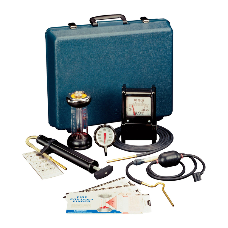
OIL BURNER COMBUSTION
TESTING KITS
The most reliable and economical way
of testing gas burner efficiency during
installation or servicing.
F Y R I T E ®
Gas Analyzers
Fast, accurate and easy to use
instruments for measuring and
analyzing carbon dioxide or oxygen.
13

Other manuals for Model 105

2

This manual suits for next models

14

Other Bacharach Test Equipment manuals

Bacharach H-10G User manual

Bacharach

Bacharach H-10G User manual

Bacharach Fyrite Pro User manual

Bacharach

Bacharach Fyrite Pro User manual

Bacharach OXOR II 19-7037 User manual

Bacharach

Bacharach OXOR II 19-7037 User manual

Bacharach Informant 2 User manual

Bacharach

Bacharach Informant 2 User manual

Bacharach Monoxor III User manual

Bacharach

Bacharach Monoxor III User manual

Bacharach IEQ Chek User manual

Bacharach

Bacharach IEQ Chek User manual

Bacharach Fyrite Pro Operating manual

Bacharach

Bacharach Fyrite Pro Operating manual

Bacharach High Performance Oilless Commercial Refrigerant Recovery... User manual

Bacharach

Bacharach High Performance Oilless Commercial Refrigerant Recovery... User manual

Bacharach Tru Pointe Operating manual

Bacharach

Bacharach Tru Pointe Operating manual

Bacharach Fyrite INSIGHT Installation and operating instructions

Bacharach

Bacharach Fyrite INSIGHT Installation and operating instructions

Bacharach Tru Pointe Ultra Instruction Manual

Bacharach

Bacharach Tru Pointe Ultra Instruction Manual

Bacharach PCA3 User manual

Bacharach

Bacharach PCA3 User manual

Bacharach 2800 User manual

Bacharach

Bacharach 2800 User manual

Bacharach MZF User manual

Bacharach

Bacharach MZF User manual

Bacharach Florite 800 Instruction manual

Bacharach

Bacharach Florite 800 Instruction manual

Bacharach 2810 User manual

Bacharach

Bacharach 2810 User manual

Bacharach DIOXOR II User manual

Bacharach

Bacharach DIOXOR II User manual

Bacharach HGM300 User manual

Bacharach

Bacharach HGM300 User manual

Bacharach INJECTOR CALIBRATOR CD3 User manual

Bacharach

Bacharach INJECTOR CALIBRATOR CD3 User manual

Bacharach ECO-2020 User manual

Bacharach

Bacharach ECO-2020 User manual

Bacharach Tru Pointe Ultra Instruction Manual

Bacharach

Bacharach Tru Pointe Ultra Instruction Manual

Bacharach Monoxor III Installation and operation manual

Bacharach

Bacharach Monoxor III Installation and operation manual

Bacharach Leakator 10 User manual

Bacharach

Bacharach Leakator 10 User manual

Bacharach TRUE-SPOT Datasheet

Bacharach

Bacharach TRUE-SPOT Datasheet

Popular Test Equipment manuals by other brands

USOUND ANANKE 3.0 UA-E1030 quick guide

USOUND

USOUND ANANKE 3.0 UA-E1030 quick guide

Tracer X111 Instructions for use

Tracer

Tracer X111 Instructions for use

HQ Power HQLE10024 user manual

HQ Power

HQ Power HQLE10024 user manual

Isotech Quick-Cal Series quick guide

Isotech

Isotech Quick-Cal Series quick guide

Silent Gliss 0997 quick start guide

Silent Gliss

Silent Gliss 0997 quick start guide

Kyoritsu Electrical Instruments Works, Ltd. 4118A instruction manual

Kyoritsu Electrical Instruments Works, Ltd.

Kyoritsu Electrical Instruments Works, Ltd. 4118A instruction manual

Unit UTD2025 series user manual

Unit

Unit UTD2025 series user manual

B+K precision 8500B Series user manual

B+K precision

B+K precision 8500B Series user manual

OEM Tools 24338 Operating instructions and parts manual

OEM Tools

OEM Tools 24338 Operating instructions and parts manual

Socket & See MFT5000 Instruction manual & specification

Socket & See

Socket & See MFT5000 Instruction manual & specification

IKALOGIC MT25C Datasheet and User Manual

IKALOGIC

IKALOGIC MT25C Datasheet and User Manual

Flo-tech FT555F manual

Flo-tech

Flo-tech FT555F manual

Black Box IT1000 manual

Black Box

Black Box IT1000 manual

Top Tronic T1105 instruction manual

Top Tronic

Top Tronic T1105 instruction manual

LineEye LE-8500XR-RT quick start guide

LineEye

LineEye LE-8500XR-RT quick start guide

Top Tronic TEL28 instruction manual

Top Tronic

Top Tronic TEL28 instruction manual

Viavi OneExpert CATV Extended Quick Start Guide

Viavi

Viavi OneExpert CATV Extended Quick Start Guide

AU Tool BT70 user manual

AU Tool

AU Tool BT70 user manual

manuals.online logo
manuals.online logoBrands
  • About & Mission
  • Contact us
  • Privacy Policy
  • Terms and Conditions

Copyright 2025 Manuals.Online. All Rights Reserved.