Wisdom GDS-5B User manual

GDS-5B CLOCK TESTER
USER
MANUAL
SHEN ZHEN WISDOM SOURCE
ELECTRONICS CO LTD
[ADRESS:Mingzhi Street, Baoan District, ShenZhen, China]

1. Overview
The new GDS-5B clock tester is suitable for precisely testing all kinds of clock circuits with
crystal oscillator working at 32.768KHz and 1Hz, for example: quartz clocks、electronic watt-hour
meter、motherboard、temperature controller、timer、electronic weigher and electronic cash
register with timer function. Its appearance is depicted as Figure.1.
Figure.1 GDS-5B clock tester
GDS-5B clock tester especially suits the fast testing of finished products or semi-finished
products. GDS-5B’s RS232 interface can be used to connect GDS-5B and computer in order to
gather testing results. Additionally, our GDS-B clock tester has a tinny probe with it, which can
suits the testing of bigger circuit boards.
GDS-5B has five stalls:
ppm:part per million, accurate to 0.1ppm
s/d:seconds/day, accurate to 0.01 seconds
s/m:seconds/month, accurate to 0.1 seconds

s/y:seconds/year
F:32.768KHz frequency deviation
Compared with the same type of products from other companies, our GDS-5B has the
following advantages:
with a more sensitive sensor in it to receive weak signal;
taking non-contact method;
thinner shell making it more easy to use and more suitable for the pipeline;
with advanced CPU and TCXO(Temperature Compensated Crystal Oscillator);
with a 16-level signal strength indicator;
with the function of alarming, and the user can set alarming range;
easy setting procedure;
accuracy is better than 0.2ppm;
extra:RS232 to connect GDS-5B to a computer
2. Features
measuring objects: quartz clock、electric meter and clock circuit board
voltage:220V AC 50Hz
testing frequency: 32.768KHz 1Hz
measurement period :1s、2s、5s、10s、20s、32s、60s
reference frequency:16.384MHZ TCXO
testing accuracy: better than 0.2ppm
range: ppm:part per million; s/d:seconds/day; s/m:seconds/month; s/y:seconds/year;
F:32.768KHz frequency deviation
signal strength indicator:16 level indicator
alarming setting range:±200ppm
volume: 13cm×27cm×29cm
display mode: four-digit LCD display
extra: RS232 to connect GDS-5B to a computer

3.Panel introduction
GDS-5B clock tester’s front and back panel are showed by Figure. 2 and Figure. 3:
Figure 2. GDS-5B clock tester’s front panel
① power switch
②mode switching button
③ signal indicator
④status indicator
⑤ sensor interface
⑥ ground
⑦12V output
⑧connect to ground of the meter optocoupler
⑨connect to positive side of the meter optocoupler
⑩interface to test the second pulse signal of electric meter’s clock chip

Figure 3. GDS-5B clock tester’s back panel
4. Usage of GDS-5B
GDS-5B clock tester is suitable for the testing of various finished and
semi-finished products.
4.1 Testing method
4.1.1 Testing of clock products(32.768KHz signal testing)
After power on self test (POST), GDS-5B enters 1Hz testing mode. We need to adjust it to
32.768KHz testing mode (chapter 4.2 shows how to choose testing mode).Connect the sensor
as Figure. 4. You just need to put clock product on GDS-5B’s sensor and GDS-5B will
automatically show the received signal strength. Here the clock product needs to be
powered on. Adjust the clock product’s position to ensure that the GDS-5B’s received signal
strength is the strongest. And then GDS-5B will show the testing results, shown by Figure.
5(taking quartz clock movement for example).

Figure. 4 connect the sensor to GDS-5B
Figure. 5 Testing result
When testing clock circuit board, we can use the probe, shown by Figure .6. First, the clock
circuit needs to be powered on. We just need to connect one end of the probe to GDS-5B, and
hold the metal part in order to lower the interference level. And then move the probe close to
the crystal oscillator.
Figure .6 Testing of clock circuit board
4.1.2 Testing of electric meter (1Hz signal testing)
After POST, GDS-5B enters 1Hz testing mode. Connect the electric meter’s optocoupler

output to GDS-5B as Figure .7 and the testing results will be displayed.
Figure .7 Testing of crystal oscillator
4.2 Usage of mode switching button
After POST, GDS-5B is in testing mode. Press the mode switching button, and GDS-5B will
enter setting mode.
When rotate the mode switching button counterclockwise, GDS-5B enters ”F”、”s/y”、
“s/m”、”s/d”、”ppm”、“PASS” and “FAIL” mode successively.
When we rotate the mode switching button clockwise, GDS-5B enters
“FAIL”、”PASS”、”ppm”、”s/d”、”s/m”、”s/y”、”F”、”SET”、”32.768KHz”、”1Hz(1s)”、”2s”
、”5s”、”10s”、”20s”、”32s” and “60s” mode successively.
When we rotate the rotary encode to a certain mode, the responding characters will flash
on the display.
Figure .8 After POST

4.2.1 Setting of testing mode and frequency mode
Setting of testing mode:After POST, press the mode switching button and GDS-5B will enter
setting mode. Then rotate the mode switching button clockwise, for example to “ppm” mode.
Now press the mode switching button and GDS-5B will enter “ppm” testing mode. The steps
can be concluded as follows:
①POST
②Press mode switching button to enter setting mode
③Rotate the mode switching button to the needed position
④Press the mode switching button to confirm and GDS-5B will return to testing mode
Setting of frequency mode:After POST, press the mode switching button and GDS-5B will
enter setting mode. Then rotate the mode switching button clockwise to “32.768KHz” mode.
Press the mode switching button to confirm and GDS-5B will enter “32.768KHz” testing mode.
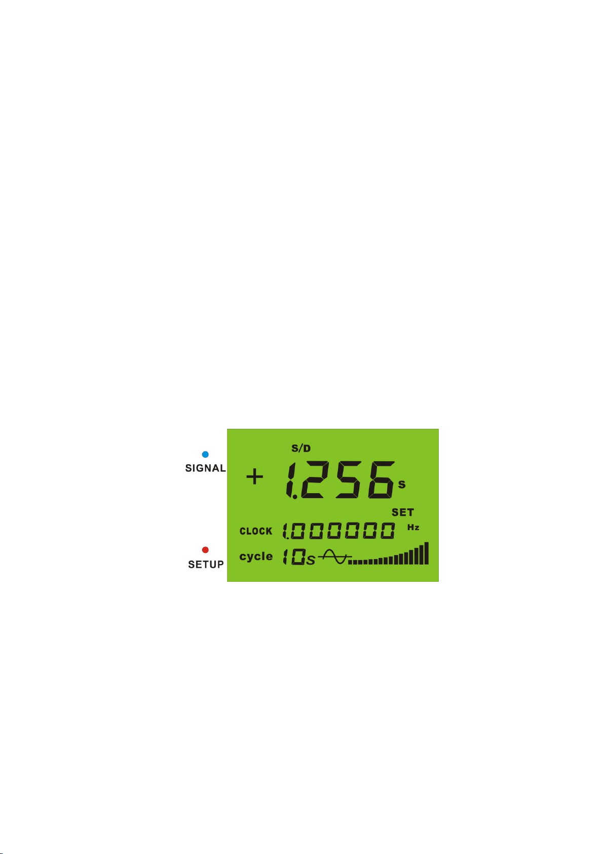
When we need to test 1Hz signal and we set the test cycle in 10s (or more), measurement
results will be displayed in three decimals as Figure .9 displays .
Figure .9 1Hz signal 10s cycle testing mode
4.2.2 Setting of alarming range
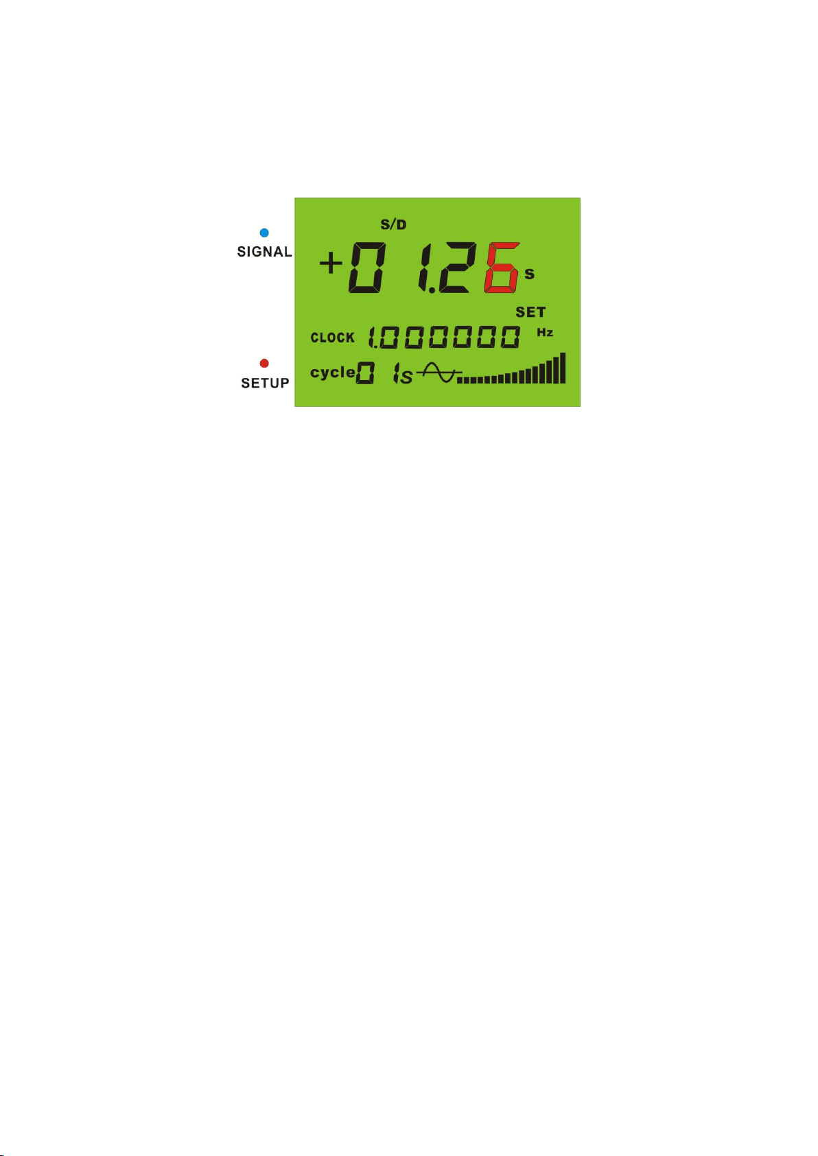
While in testing mode, press the mode switching button to enter setting mode. Then rotate
the mode switching button counterclockwise to “FAIL” mode. Press the mode switching button to
change alarming range. Now we can rotate the mode switching button to choose the position to
be changed as shown by Figure .10. After choosing the right position, press mode switching
button and now we can change the value of this digit by rotate the mode switching button (now

this digit will flash slower). Press the mode switching button to save this digit. Then we can
choose other digits through rotating. It has to be announced that when the value for example
1.26s is saved, the alarming range has been set as ±1.26s.
Figure .10 Setting of alarming range
This can be concluded as follows:
①POST
②Press the mode switching button to enter setting mode.
③Rotate the mode switching button to “FAIL” mode.
④Press the mode switching button to enter the alarming range setting mode (GDS-5B
defaults in “s/d” mode so if we need to set the ppm alarming range, we need to make
sure GDS-5B works in “ppm” mode) .
⑤Press the mode switching button and rotate it clockwise to change the value of the last
digit
⑥Press the mode switching button and the flashing digit will move forward. Change it as
before. As is the same with other digits.
⑦After the value is set, press the mode switching button for three seconds to save the
value and return to testing mode. And we complete the alarming setting procedure.
4.3 Turning on and off of alarming function
4.3.1 Turning on of alarming function
①In testing mode, press the mode switching button to enter setting mode. Now the “SET”
indicator is flashing.

②Switch the mode switching button counterclockwise 6 times to ”PASS” mode.
③Press the mode switching button again will turn on the alarming function and GDS-5B
will return to testing mode.
Figure .11 Turn on alarming function
Now the indicator “NUMBER” is on and GDS-5B will compare testing results with the
alarming range. If the testing results is out of the alarming range, the “PASS” indicator will shut
down and the “FAIL” indicator will be on. At the same time, GDS-5B will alarm four times to
inform the user.
4.3.2 Turning off of alarming function
①In testing mode, press the mode switching button to enter setting mode. Now the “SET”
indicator is flashing and the “NUMBER ” indicator is on.
②Switch the mode switching button counterclockwise 6 times to ”PASS” mode.
③Press the mode switching button again will turn on the alarming function and GDS-5B
will return to testing mode.

Figure .12 Turn off the alarming function
Now the indicator “NUMBER” is off and GDS-5B will not compare testing results with the
alarming range.
http://www.szgup.com
Table of contents
Popular Test Equipment manuals by other brands

Agilent Technologies
Agilent Technologies N9360A installation guide

Tektronix
Tektronix 2445 instruction manual

clare
clare G2000 Operator's manual

SIGLENT TECHNOLOGIES
SIGLENT TECHNOLOGIES SDS1000X Series user manual

Envitec
Envitec AlcoQuant 6020 operating instructions

bioMerieux
bioMerieux SAMPL'AIR LITE user manual

OPTOKON
OPTOKON OFT-920 user manual

Elenco Electronics
Elenco Electronics RS-400/K-37 Assembly and instruction manual

Lite-Check
Lite-Check 912 manual

Agilent Technologies
Agilent Technologies 5530 reference guide

PRESIDIUM
PRESIDIUM Duo Tester User handbook

Keysight Technologies
Keysight Technologies InfiniiVision 1000 X Series user guide