INTRODUCTION
First of all, we thank and congratulate you for purchasing this product manufactured by Golmar.
Our commitment to achieving the satisfaction of customers like you is manifested through our ISO-9001 certification
and the manufacture of products like the one you have just purchased.
Its advanced technology and strict quality control will ensure that customers and users enjoy the numerous features
that this device offers. To get the most out of them and ensure proper operation from day one, we recommend that you
read this instruction manual.
CONTENTS
2
SAFETY PRECAUTIONS
-Avoid overtightening the screws of the monitor connector.
-Always disconnect the power supply before installing or making modifications to the device.
-The fitting and handling of these devices must be carried out by authorised personnel.
-All of the wiring must run at least 40cm away from any other wiring.
-Install the monitor in a dry protected location free from the risk of dripping or splashing water.
-Do not place in humid, dusty or smoky locations, or near sources of heat.
-Before connecting the device to the mains, check the connections between the door panel, power supply, distributors
and monitors.
-Always follow the instructions contained in this manual.
Introduction....................................................................................................................................................................2
Contents........................................................................................................................................................................ 2
Safety precautions........................................................................................................................................... 2...............
Characteristics............................................................................................................................................................ .3.. .
System operation......................................................................................................................................... .3................. .
Description of the monitor.............................................................................................................................................. ...
................................................................................................................................................................ .4.
Description
............................................................................................. 4..Status LED and description of the connection terminals
............................................................................................................................................... .5..........Function buttons
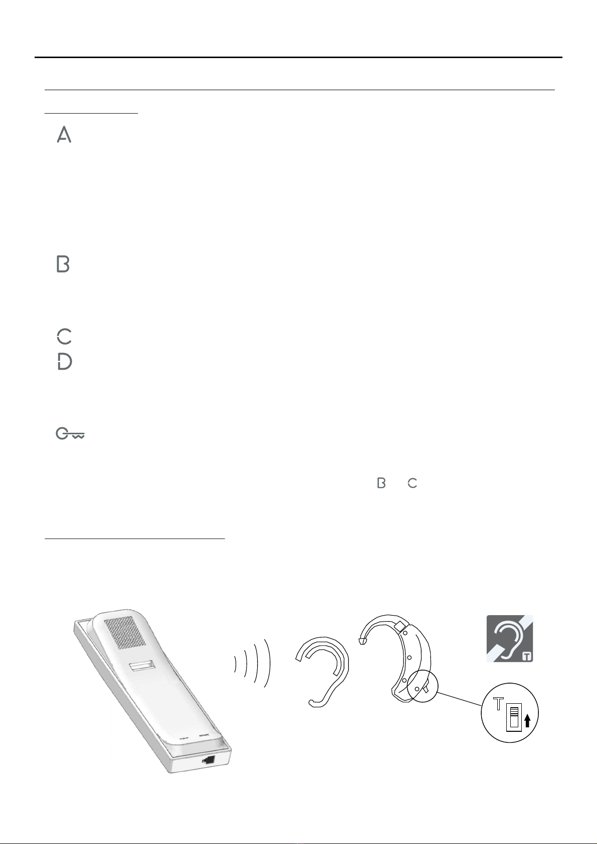
............................................................................................................................. .. 5.Communication with hearing aids
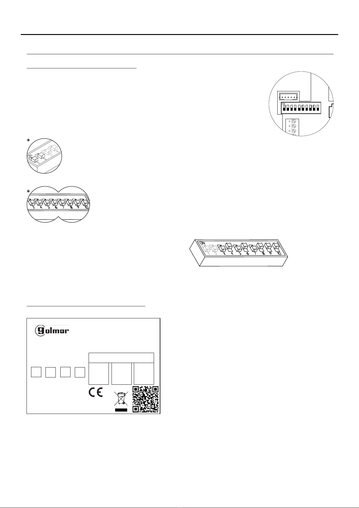
.................................................................... ....................................................................................... 6.SW1 DIP switch
.......................................................................................... .................................. 6Description of the identification label
................................................................................ .............................. 7RJ-45 connector (installation with UTP cable)
.......................................................................................... ............................. 7End of line jumper and EL-562S module
.......................................................................................................8Installing the monitor in a wall mounting connector
....................................................................................... ............................ 9.Installing the monitor in an embedding box
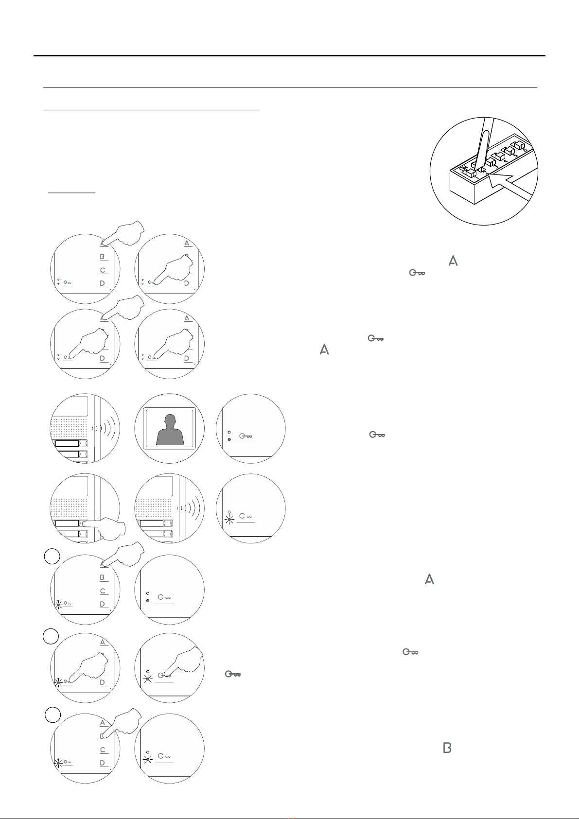
Monitor programming............................................................................................................................. ......... 10........ . -11
Rapid monitor programming................................................................................................................... ............. 1......... . 1
Advanced programming (monitor functions)....................................................................................................... ..............
Men 1....................................................................................................................................................................... 1u 2
- .......................................................................................... ..... . .. 1.. . . 2.
Activating/deactivating the doctor mode function
- ........................................................................................................ ...... 1................... .. 2Changing the ringtone melody
Men 2....................................................................................................................................................................... 1u 3.
- ....................................................................................................................... 1..... 3
Changing the function of button
- .................................................................................................................... . 1...... . 3Changing the function of button
- .......................................................................................................................... . 1. 3.Intercom with Tekna Plus monitors
Men 3....................................................................................................................................................................... 1u 4.
- .......................................................................................................... ................ 1.................. 4.
Repeating the ringtones
- .......................................................................................... . 1.............. . 4.Adjusting the 'door panel communication time'
- ................................................................................................................ . 1............ 4Adjusting the 'door panel call' time
- ............................................................................................................................... . 1......... 4Activating the in-call video
Men 4....................................................................................................................................................................... 1u 5
- .......................................... . 1........... . 5
Setting all of the monitor's advanced programming options to the 'default setting'
Optional connections............................................................................................................................................... .........
- .................................................................................................................... .. 1. 6...................
Activating auxiliary devices
- ...................................................................... 1............. .. 6Input for auxiliary button to activate the door panel lock release
- ................................................................................................................. . 1.................. 7.Intercom within an apartment
- ........................................................................... . 1................. . 7.Button for receiving calls from the apartment front door
- ............................................................................. .1............................................ ............. 8Activating a second camera
Cleaning the monitor..................................................................................................................................... ........ .. 1.... . . 8
Wiring diagrams..................................................................................................................................... .1 -................. 9 20
Notes............................................................................................................................................................................21
Compliance..................................................................................................................................................................22
TEKNA-S PLUS MONITOR