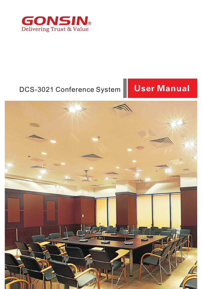
GONSIN DCS-3024 User manual

1

1
Safety Notes
1. Please carefully read this document
before installing and using the
equipment.
2. Please keep this document for future
reference.
3. Observe “Cautions” in all operation
guides.
4. Observe the rules and principles in all
operation guides.
5. Clean equipment: before cleaning the
equipment, power it off and then
disconnect all units of the equipment.
Use dry soft cloth to clean the
equipment.
6. Do not use any nonconforming
accessory or fitting without approval
from the Company. It is likely to cause
hazardous accident.
7. Do not put the equipment in humid
places so as not to cause equipment
damage or danger.
8. Do not place the equipment on an
unstable table; prevent equipment
vibrating during transportation to avoid
damage to the equipment. Select
proper package or original package for
transportation.
9. Keep the equipment room ventilated
so as to prolong the service life of the
equipment.
10. Service voltage: America and Japan:
AC 110V-120 V and 60 Hz Eurasia:
AC 220V -240 V and 50 Hz.
11. Power socket: three-pin Ground
Socket.
12. Do not place heavy objects on
extension cables necessary for
equipment connection. there is Make a
detour if routing is required to ensure
normal operation of the system.
13. Connect all conference units in the
system equipments in the whole
system may run abnormally. Contact
GONSIN after-sale service center in
case of special requirements.
Technical support Tel: 0757-22360959.
14. Unless permitted by the Company, do
not disassemble shell and avoid any
hard conductor or liquid from leaving
or permeating into the shell.
15. Do not disassemble the equipment on
your own when your equipment needs
service. Contact the customer service
center of GONSIN: 400-883-1138.
16. All GONSIN products shall be against
the warranty card based on system
category, except for product issues
resulting from man-made reasons or
force majeure, for example:
A. Equipment is dropped and broken
man-made reasons;
B. Equipment is damaged due to
misoperation by operators;
C. Some equipment spare parts are
damaged or missing due to
arbitrary disassembly;
D. Equipment is dropped and broken
due to natural disasters.

2
17. Use specific cables to connect
equipment.
18. Turn off the power switch and remove
the plug in case that the equipment is
not used for a long time.
19. Keep the Warranty Card in appendix
safe.The card serves as a basis for
future maintenance free of charge.
Caution: do not open the cover; otherwise,
a risk of electric shock.
Before connecting, operating or adjusting
this product, read this document carefully.
This label is attached to the back of the
equipment to save area.
The lightning sign reminds users that
hazardous voltage that is not insulated is
likely to trigger.
The exclamation mark in the triangle
reminds users to operate and maintain the
equipment on the accompanied operation
maintenance instructions.
Caution: do not expose the equipment to
rain or humid places to avoid fire and
electric shock.
Note: only qualified electrical
engineers are allowed to install equipment.
Remove the power plug: the
equipment is powered on when power
cable is inserted into the power socket
irrespective of a power switch or not;
however, the equipment cannot be
operated until the ON/OFF button is
switched to “On”. The power cable is the
main power source for cutting off all units.

3
Precautions for Lithium Battery Use
In case of the following abnormality during use, turn off the power switch, take out the
battery, and keep the equipment away from fire; if not, there is a risk of fire or explosion.
——The battery is leaking, changing color, deformed, or damaged.
——The battery is smoking or smelly.
Do not weld or modify the battery or change its form; otherwise, the battery circuit may
be damaged, resulting in a fire, leakage, even explosion.
Avoid the battery shorting (anode and cathode) by electric wire or metal and do not place
the battery and metal(e.g. chain or key) together for storage or transportation; otherwise,
the battery may be heated up, resulting in leakage, fire or explosion.
Do not heat the battery or throw the battery into fire; otherwise, the safety valve or
protective circuit of the battery may be damaged, resulting in fire or explosion.
Do not set the battery in water or moisten the battery anode/cathode; otherwise, the
battery will be corroded and heated up, resulting in, leakage, fire, or explosion.
Use specified charger to charge the equipment. Avoid reversing the battery anode and
cathode; otherwise, the battery may be heated up, resulting in leakage, fire or
explosion.
Do not place the battery near fire or expose the battery to high-temperature environment
(60°C; e.g. in car); otherwise, the battery circuit may be damaged and heated up,
resulting in fire, leakage, even explosion.
The battery must be used on specified equipment model; if not, the battery may be
heated up, resulting in leakage, fire or explosion.
Do not drop or vibrate the battery; otherwise, the battery circuit may be damaged and
heated up, resulting in a fire, leakage, even explosion.
In case the battery leakage enters eye, use clean water to flush the eye and seek
medical care immediately; if not, blurred vision may occur.
In case the battery leakage stains clothes or skin, use clean water to flush it; if not, skin
may be damaged.
Battery capacity will be too low if the lithium batteries are left unused for a long
time, which will damage the batteries. Remove the batteries and make sure they
are fully charged every three months.
Notes:
GONSIN reserves the right to change this document without prior notice.
To obtain more documentary materials, contact the local after-sale service
center. GONSIN welcome your feedback.

4
Content
Safety Notes.................................................................................................................... 1
Precautions for Lithium Battery Use............................................................................ 3
Chapter 1 Introduction
............................................................................................... 6
1.1 System connection diagram............................................................................ 6
Chapter 2 Congress Server
..................................................................................... 8
2.1 Overview............................................................................................................. 8
2.2 GONSIN30000S Functions and Indicators................................................... 9
2.2.1 Basic Functions............................................................................................................... 9
2.2.2 Server Indicators........................................................................................................... 10
2.3 Server Installation........................................................................................... 12
2.4 Connection....................................................................................................... 12
2.4.1 Connection with Congress Terminal.......................................................................... 12
2.4.2 Connection with Wireless conference access points extend cascading.............. 12
2.4.3 Connection with Wireless AP and Control PC..........................................................13
2.4.4 Connection with Mixer or Amplifier.............................................................................13
2.4.5 Connection with Camera..............................................................................................14
2.4.6 Connection with the Dome Controller........................................................................ 15
2.4.7 Congress Server Setting and Operation................................................................... 16
Chapter 3 Compositions of the Wireless Conference System.............................. 19
3.1 Functions and Indicators of the Wireless Congress Terminal................. 19
3.1.1 Overview.........................................................................................................................19
3.1.2 Basic Functions............................................................................................................. 19
3.1.3 Basic Functions............................................................................................................. 19
3.2 Functions and Indicators of Wireless AP.....................................................20
3.2.1 Basic Functions............................................................................................................. 21
3.2.2 Indicators........................................................................................................................ 21
3.3 Functions and Indicators of Charging Case................................................22
3.3.1 Basic Functions............................................................................................................. 22
3.3.2 Indicators........................................................................................................................ 22

5
3 . 4 Connection of Congress Terminal............................................................. 23
Chapter 4 Wireless Network Design......................................................................... 24
4.1 Introduction.......................................................................................................24
4.2 Selective frequency hopping technology.....................................................24
4.3 Frequency Range............................................................................................24
4.4 Others............................................................................................................... 24
4.5 Installation Rules............................................................................................. 25
Chapter 5 WEB access............................................................................................... 26
5.1 The Way of WEB Access..............................................................................26
5.2 The WEB Page................................................................................................26
5.2.1 System state.................................................................................................................. 26
5.2.2 System Setting...............................................................................................................27
5.2.3 Frequency Point Setting...............................................................................................28
5.2.4 IP Device Setting...........................................................................................................28
5.2.5 MIC unit information......................................................................................................29
5.2.6 Web Password Management...................................................................................... 30
5.2.7 Camera Setting..............................................................................................................30
5.2.8 Media Broadcast Management................................................................................... 31
Chapter 6 Environment and Maintenance................................................................32
6.1 System Requirements.................................................................................... 32
6.2 Public Environment Requirements............................................................... 32
6.2.1 Technical Requirements on Public Environment......................................................32
6.2.2 System Operation Requirements............................................................................... 32
Appendix........................................................................................................................ 34

6
Chapter 1 Introduction
GONSIN DCS congress system boasts superior performance, and it is applicable to
conferences of different sizes. The congress terminal is easy to operate: press the speaking key
to speak and rotate the volume knob in two directions (“+” and “-”) to adjust the volume of the
built-in loudspeaker; system maintenance does not need much skill as well: technicians can
operate the terminal after a short period of training.
System composition:
The DCS congress system is composed of the congress server, wireless congress terminals
(for the chairman and delegates), wireless AP WAP-30C, HUB-D45, PC (optional), conference
management software (optional), high- speed dome cameras (optional), monitoring antenna
(optional), and audio devices and display devices.
1.1 System connection diagram

7
This document is applicable to the following product models:
Congress server
GONSIN30000S (With discussion, automatic camera tracking function, USB recording and
storage function)
Wireless AP
WAP-30C
Wireless Conference Terminal
DCS-3024C-W Wireless conference chairman terminal
DCS-3024D-W Wireless conference delegate terminal
Pluggable Microphone Stem
MIC-410*¢14. 5-Y 410mm Pluggable Microphone Stem (Black)
MIC-410*¢14. 5-Y 4 10mm Pluggable Microphone Stem (Silver)

8
Chapter 2 Congress Server
2.1 Overview
The DCS congress server GONSIN30000S is the core of a congress system. It can be
connected to WAP-30C or WAP-30I (for increasing the number of listening units and
simultaneous interpretation units) as well as HD matrix, mixer, power amplifier, and PC over
corresponding interface. The server acts as a bridge to connect system hardware and control
software. It can work independently or be connected with a PC to allow operator to use the
conference management software for management and control.
Product model:
GONSIN30000S
Congress server (with discussion and automatic camera tracking functions)
DCS conference server GONSIN30000S is the core part of the conference system, which can
be connected to the following devices: WAP-30C wireless access point, by extending the
cascade WAP can increase the maximum number of speakers to 8 people; Under the off-line
condition, the automatic camera tracking function can be realized by adding the camera ball
machine and matrix.Built-in high and bass compensation function, high and bass can be
compensated to achieve perfect sound quality;Built-in feedback suppressor, which can
effectively prevent the microphone howling.The corresponding interface can be connected to
high-definition matrix, mixer, power amplifier, computer and other equipment.The server is also
the bridge between the system hardware and the control software to connect and control, it can
work independently, but also in need of more complex meeting management and control,
connect the computer with the system software to be completed by professional operators.
Offline function:
Global sound sensitivity adjustment (high, medium, low);
Has the function of writing unit number;
Supports high-definition camera tracking system, up to 8 high-definition camera ball players;
Can be set to open any 1 to 3 delegate microphones other than the chairman and vice
chairman at the same time (the maximum number of open microphones can be up to 8
after the extension of cascading WAP);
You can choose three modes of speech:
Limit speech mode (AUTO)

9
FIFO mode (FIFO)
Voice control mode (VOX)
High and bass compensation to achieve perfect sound quality;
Has the function of suppressing scream.
2.2 GONSIN30000S Functions and Indicators
2.2.1 Basic Functions
1. Based on Linux operating system platform development, built-in DSP digital audio processor,
with noise suppression function;
2. Adopt high contrast OLED screen to display the current status of the system, and provide
setting menus in Chinese/English and other languages;
3. Adopt FS-FHSS frequency hopping technology, with spectrum monitoring and screening
functions, support carrier frequency intelligent hopping, and automatically select clean
frequency points when speaking each time;
4. The use of digital wireless communication technology, anti-interference, anti-multi-path fading,
not affected by light and infrared, can be used in the WLAN environment stable;
5. The use of low distortion, low delay transmission technology, support 48KHz audio sampling
frequency;
6. The server can adjust the sensitivity of the conference terminal (0-3 level), according to the
field situation to adjust the best effect;
7. The server supports setting the Host ID and automatically or manually assigning the ID to the
conference terminal;
8. Speech function: limited speech mode (AUTO), FIFO mode (FIFO), voice control mode
(VOX);
9. Voice control mode: in the voice control mode, the microphone automatically opens when
speaking, the sensitivity of the voice control can be adjusted (L0~L2), and the automatic
shutdown time can be set;
10. Number of speakers: The number of conference terminals can be opened at the same time
is 4 (including 1 chairman terminal +3 delegate terminals), the server supports two WAP
cascading, the maximum number of speakers can be 8, and the setting of multiple chairmen
and vice-chairmen can be supported;
11. The server supports functions of one-button shutdown, one-button sleep and one-button
wake-up, which can effectively reduce the workload of the meeting;
12. The server provides USB interface, which can realize recording function;
13. With the video matrix or switcher, HD camera, can achieve HD automatic camera tracking
function, support preset panoramic position;

10
14. With intelligent speech recognition system, can achieve speech transcription function;
15. Between the server and the control computer using TCP/IP connection control mode,
support Web management function:
1) The server state can be monitored in real time, including the number of speakers, speech
mode, connection state, internal core voltage and fault warning information of the server;
2) Support Web to set the number of speakers, speech mode, microphone sensitivity, volume
control and other system Settings;
3) Support to view version information, support network update and local update;
4) Real-time monitoring of microphone terminal status, including online status, signal strength,
frequency status, battery remaining power and other information;
5) Support the control of wake-up, sleep and shutdown of the microphone through Web;
6) Support unit write number, HD camera tracking setting and other system operations through
the Web;
7) Support media playback management through Web, built-in MP3 recording and
MP3/FLAC/WAV/AAC playback function, can play recording files and stored audio files.
2.2.2 Server Indicators
Front side:
1.Power switch (POWER)
Note: The server takes a period of time to
start up. Before the server is fully started
up, do not operate the congress terminals.
2.Backlight LCD
Show various kinds of information (such as
operation mode and language) and provide
simplified Chinese, English language
system Settings menu.
3. Operation buttons: up/down/left/right arrow
buttons
4.OK button
5.Bass adjustment knob (BASS)
6.Treble adjustment knob (TREBLE)
7. Volume knob (VOL)

11
Back side:
8.RS-485 interface (RS-485 TO CAMERA).
This interface has two pairs of connection
terminals and it is used for connecting to
cameras that support PELCO-D\PELCO-
P\Visca protocol.
9. RS-232 serial port. This interface is used
for connecting to a PC for software control.
10.Standard POE power supply network
interface.
It can be used to connect control PC,
switches or connect WAP, and also connect
voice recognition systems.
11.USB recording and storage function.
12.This interface is used for connecting to
listen antenna.
13.One is the RCA audio input interface and
the other is the RCA audio output interface.
14.One-channel XLR balanced audio output.
15.Power interface (AC 110-220V 50Hz).

12
2.3 Server Installation
The congress server is 1U high, and therefore it can be installed in a 19-inch rack.
It has two accompanied brackets. Screw up the bracket fixed in two sides of the
congress server, put the congress server into the rack, then screw up it with the rack
screws, as shown in the following figure:
2.4 Connection
2.4.1 Connection with Congress Terminal
To connect the congress server with a wireless terminal, i t i s n e c e s s a ry to c o n n e c t a
n e tw o r k c a b l e e x c e e d in g c a t e g o r y 5 o r a b o v e t o W A P - 30 C in t h e
co n f e r e n c e h a l l f ro m t h e PO E p o w er s u p p l y ne t w o r k p o r t R J - 4 5 of t h e
s e r v e , as shown in the following figure:
2.4.2 Connection with Wireless conference access points
extend cascading
When the server is connected to the wireless conference access point, pay attention to the
required coverage of the conference venue. If the area to be covered by the conference venue

13
is too large or the maximum number of speakers needs to be increased, extensible cascaded
WAP can be used.The following figure shows the wiring diagram:
2.4.3 Connection with Wireless AP and Control PC
The successful communication between the congress server and a wireless terminal
must be supported by a wireless AP WAP-30C to perform signal conversion. The
conference server has 4 RJ-45 connectors, any one of which can be connected to the
control computer. The following figure shows the wiring diagram:
2.4.4 Connection with Mixer or Amplifier
The conference server has one RCA connector unbalanced audio input (LINE IN), one
RCA connector unbalanced audio output (LINE OUT), and one balanced audio output
(CANON). Connected to the sound amplification system, the speaker's voice can be
amplified and output.The connection only needs to use an RCA unbalanced audio
output "Line OUT" or a balanced audio output "Canon" to connect to the audio output
interface of the server, and the other end is connected to the input end of the sound
amplification system. The following figure shows the wiring diagram:

14
-
+
-
+
2.4.5 Connection with Camera
Among the three groups of wiring from the camera (for details on camera operation, refer to
the camera operation guide), two groups of wiring are used for connecting to the congress
server (power of the camera is supplied directly from the control room). One group is the HD
video wiring, which is implemented by connecting the video output of the dome camera to
the SDIINPUT of the HD matrix over an BNC connector; where, number 1–input 1; number
2–input 2. The panoramic preset position and the video tracking of the chairman terminal are
completed by number 1 camera. The other group is the RS-485 wiring. Generally, use
network cables for communication and select a pair of wires as the “+” and “-” of the RS-
485 cable. Refer to the following figure:
GONSIN30000S use 8I+8O HD matrix with the SDIOUTPUT, which is BNC connector.
Connect the matrix to a display device (such as monitor or converter) using an HD video cable.
Refer to the following figure:

15
Note: Please refer to the software instructions for setting the camera tracking Settings.
2.4.6 Connection with the Dome Controller
Make sure that the GX-KB01 dome controller ’s protocol and baud rate are already
preset (please see dome controller user manual for the settings). Use a 2-pin twisted
pair cable to connect 485+ and 485- of dome controller to 485+ and 485- of central
control unit. Please note that the RS485 control cable of dome camera is already
connected with RS485 control cable of central control unit.
The control cable of dome controller can also be connected to control cable of dome
camera.

16
2.4.7 Congress Server Setting and Operation
The LCD screen has five keys:
“▲”,“▼”,“▶”,“◀”, and “OK”. After entering
the setting interface, the current option is
displayed on a contrast background. The
leftward and rightward arrow buttons are
used to enter or exit a menu.
(1) Status: when the system works normally,
the OLED shows the number of active
microphones,speaking mode and status, as
shown in the following figure:
(2) Active mics: Press OK to enter the setting
interface, press arrow buttons to select the
value after Active mics, and then press “▲”
or “▼” key to change the number of mics
(1/2/3) that can be activated at the same time.
(3)Speaking mode: on the setting interface,
press arrow buttons to select the value after
Mode and press “▲” or “▼” key to change a
speaking mode: AUTO or FIFO or VOX.
VOX: on the setting interface, press arrow
buttons to select and enter the “VOX” setting
interface. The interface has the following
parameters for users to set:
①Mic time-out: the time when there is no
voice input in the unit can be set to 006
seconds, 030 seconds, 060 seconds, 120
seconds, 180 seconds.
②VOX Level: the sensitivity of all units are
be set uniformly by the host, which is divided
into three levels: L1, L2 and L3. The
sensitivity of picking up the sound source will
increase successively, and the microphone
will automatically turn on the microphone
from the off state.
(4)System: on the setting interface, press
arrow buttons to select and enter the
“System” setting interface. The interface has
the following parameters for users to set:
①Volume control lock
If volume control is locked, rotating the
volume knob will not work.
If volume control is unlocked, rotating the
volume knob will work.
②Record:
If record is close, recording function will be
turned off.
If record is open, the recording function will
be turned on. The FAT32 formatted U-disk
need to be inserted into the USB port of the
server to record the conference content. Turn
off the recording function and save it as an
audio file.
③Shutdown: Enter the “Shutdown” interface
and select "Yes". The system will shut down

17
all congress terminals; if you select "No", the
system goes back to the preceding menu.
④Host ID: enter the "Host ID" interface to
set the host ID of the system. The default
host ID is 0000.
Functional description: host ID is a code used
within a system for internal communication.
Communication can be successful only when
the host ID of the system is consistent with
that of a congress terminal. Within a building,
set different host IDs for multiple wireless
congress systems to avoid mutual
interference.
⑤Sleep: enter the “Sleep” interface and
select "Yes". The system will put the all
congress terminals into sleep state; if you
select "No", the system goes back to the
preceding menu.
⑥Wake up: enter the “Wake Up” interface
and select "Yes". The system will wake the
all congress terminals from sleep state; if you
select "No", the system goes back to the
preceding menu.
⑦About: enter the “About” interface will
display the host version information, such as
the server version is 5.0. Press the "▶" key
to enter IP address information interface,
such as server IP is 192.168.30.8. Press
"OK" to return to the previous menu.
(5)Unit ID No.: select the "Unit ID No." setting
and press the "▶" key to select the last three
numbers. The range of number writing is
from 1001 to 1999. After selecting the last
three numbers, "▲" or "▼" can be pressed
to change the number. After the appropriate
number, press the "OK" key to enter the
number writing state, when the number is
completed, you can press the "OK" key again
to return to the previous menu.
(6)Language: after entering the "Language",
the "▲" or "▼" key can be pressed to select
English/Chinese. After the selection is
completed, press the "OK" key to confirm and
return to the previous menu.
(7)Sensitivity: after entering the "Sensitivity",
the "▲" or "▼" key can be pressed to adjust
the sensitivity of the microphone in batches.
Four levels from 00 to 03 are adjustable.
Press the "OK" key to confirm and return to
the previous menu.

18
(8)DSP: after entering "DSP", the "▲" or "▼"
key can be pressed to select on or off. After
selection, press "OK" to confirm and return to
the previous menu.
(9)Bcast set (Broadcast set): In the setting
interface, use the buttons to select "bcast"
and enter the broadcasting settings. The
broadcasting settings include the following:
①Broadcast: After selecting "Broadcast", the
"▲" or "▼" key can be pressed to select on
or off. After the selection is completed, press
the "OK" key to confirm and return to the
previous menu.
②Bcast vol (Broadcast volume): After
selecting "bcast vol", the "▲" or "▼" key can
pressed to select the broadcasting volume,
which can be adjusted in eight levels from 01
to 08.
After selecting, press "OK" to confirm and
return to the previous menu.
(10)Senior: In the setting interface, select
"Senior" through the buttons to enter the
senior settings. The senior settings include
one of the following two states:
①Unlock: After entering the senior settings,
the status displays "Unlock". At this time, the
device can be used without restrictions.
"Lock" can be selected by pressing the " ▲"
or " ▼" key, and select "Yes" after entering
the lock. To lock; select "No" to return to the
previous menu.
②Locked: After entering the senior settings,
the "countdown" displays the remaining
hours of the device currently available.
"Unlock" can be select by pressing the "▲" or
"▼" key, and the device can be unlocked
after entering the correct password.

19
Chapter 3 Compositions of the Wireless
Conference System
3.1 Functions and Indicators of the Wireless Congress
Terminal
3.1.1 Overview
The congress terminal is essential for a conference participant and it connects with a
congress server via the wireless AP. Functions available to participants vary with the
type of a conference unit, including listening, speaking, and requesting to speak.
Product models:
DCS-3024C-W Chairman terminal with basic discussion
DCS-3024D-W Delegate terminal with basic discussion
3.1.2 Basic Functions
1、Battery capacity detection
2、Low-voltage alarm and automatic shutdown
3、Hold and press the MIC button on the MIC base to turn on/off the terminal
4、RUN indicator
5、Attendance registration by button pressing or prosthesis registration
6、Speaking mode: AUTO or FIFO; hear a speaker via the headphone or built-in
loudspeaker; volume is adjustable
7、Automatic video tracking and panoramic preset position; in support of SD and HD
video tracking
8、Micro USB interface for charging; lithium battery is removable for batch charging
3.1.3 Basic Functions
Table of contents
Other GONSIN Conference System manuals
Popular Conference System manuals by other brands

Ricoh
Ricoh P3500 user manual

CAMBRIDGE
CAMBRIDGE Qt Conference Room Edition Installation and operation guide

Avaya
Avaya Aura Communication Manager Branch i120 Installation, quick start

Aeta Audio Systems
Aeta Audio Systems SCOOP STUDIO Getting started

Contacta
Contacta IL-K300 Installation & user guide

Highfive
Highfive RB1 quick start guide