Goodman MBR User manual

SS-GMBR www.goodmanmfg.com 11/15
Supersedes 9/15
* Complete warranty details available from your local dealer or at www.goodmanmfg.com. To receive the 10-Year Parts Limited Warranty, online
registraon must be completed within 60 days of installaon. Online registraon is not required in California or Quebec.
MBR
Multi-Position, Multi-Speed
Modular Blower
With PSC Motor
Contents
Air Handler Nomenclature.................... 2
Heater Kit Nomenclature...................... 2
Product Specicaons........................... 3
Dimensions ............................................ 4
Airow Data ........................................... 5
Heat Kit Data.......................................... 6
Wiring Diagram...................................... 7
Product Features
• Direct drive, mul-speed PSC blower motor
• Cooling or heat pump applicaons:
upow, downow, and horizontal
• Blower secon usable as an electric furnace
• Control board includes a fan delay in the cooling
mode and is isolated from the air stream
• Intended for use with CAPF/
CHPF cased evaporator coils
• CAPF/CHPF coils are equipped
with a check owrater
• AHRI cered; ETL listed
• Painted, galvanized steel cabinet
• Horizontal or vercal conguraon capabilies
• 21" depth for easier ac access
• Foil-faced insulaon is glued in place and covers
the enre blower case to reduce operang
sound and cabinet condensaon
• Galvanized, leather grain-embossed nish
• 3 kW – 21 kW electric heat kits available
• Cabinet air leakage less than 2% at 1.0 inch H₂0 when
tested in accordance with ASHRE standard 193
• Cabinet air leakage less than 1.4% at 0.5 inch H₂0
when tested in accordance with ASHRE standard 193

2www.goodmanmfg.com SS-GMBR
Nomenclature
UnitType Revisions
HKR AirHandlers&PackagedUnits EngineeringRevisions
HKA AirHandlers
HKP PackagedUnits
CircuitBreaker
None Singleor3PhaseKit;
Phase NoCircuitBreaker
None SinglePhase C SinglePhaseKitw/
3 ThreePhase CircuitBreaker
HeatingCapacity@240Volts
5 4.75kW 15 14.25to15.00kW
8 7.00kW 20 19.00to19.60kW
10 9.50kW
* A
1
2
3
4,5
11
HKR * 05
1,2 3,4 5,6 7,8 9 10 11
DesignSeries Electrical
MB ModularBlower 1208230/60/1
MotorSpeed Revisions
R MultiSpeed AFirstSeries
CircuitBreaker
AirflowDelivered ANoCircuitBreaker
08 800CFM BCircuitBreaker
12 1200CFM
16 1600CFM FactoryinstalledElectricHeat
20 2000CFM 00NoHeat
RMB 112 00 A A

SS-GMBR www.goodmanmfg.com 3
Model MBR0800AA-1 MBR1200AA-1 MBR1600AA-1 MBR2000AA-1
Blower
Diameter 9" 9" 10" 10"
Width 6" 8" 8" 10"
Electrical Data
Voltage 208 / 230 208/230 208 / 230 208 / 230
Min Circuit Ampacity 1.9 33.8 4.9
Max. Overcurrent Device (Amps) 15 15 15 15
Blower Motor
Horsepower (HP) ¼⅓ ⅓ ½
Ship Weight (Lbs.) 62 62 73 84
• Minimum Circuit Ampacity (MCA) and Maximum Overcurrent Protecon (MOP) for blower without supplemental heat installed. Refer to unit nameplate for
these specicaons with approved accessory heaters installed.
Product Specifications

4www.goodmanmfg.com SS-GMBR
Dimensions
Top View
8⅞"
10¼"
16 ½"
13¼"
11¼”
23 ½"
SMALLMEDIUMLARGE
8.840
10.159
16.500
11.029
11.209
20.021
13.178
11.209
23.464
17½"21"24½"
11"
11¼"
20⅛"
W H D
MBR0800* 17½" 26" 21"
MBR1200* 17½" 26" 21"
MBR1600* 21" 30" 21"
MBR2000* 24½" 30" 21"
Side and Front Views

SS-GMBR www.goodmanmfg.com 5
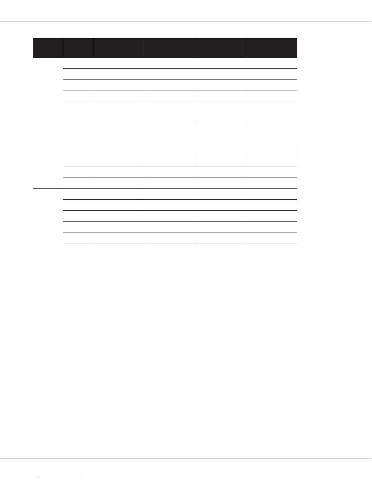
Airflow Data
Speed Static MBR0800**-*
SCFM
MBR1200**-*
SCFM
MBR1600**-*
SCFM
MBR2000**-*
SCFM
High
0.1 1,240 1,500 1,800 2,160
0.2 1,170 1,460 1,740 2,080
0.3 1,120 1,360 1,680 1,990
0.4 1,060 1,280 1,610 1,890
0.5 980 1,200 1,520 1,790
0.6 900 1,110 1,430 1,690
Medium
0.1 900 1,380 1,540 1,730
0.2 850 1,320 1,490 1,670
0.3 790 1,270 1,450 1,590
0.4 740 1,200 1,400 1,520
0.5 680 1,140 1,350 1,420
0.6 605 1,040 1,280 1,320
Low
0.1 650 1,170 1,130 1,520
0.2 590 1,130 1,100 1,450
0.3 540 1,080 1,070 1,360
0.4 500 1,020 1,030 1,290
0.5 430 950 990 1,200
0.6 330 830 930 1,090
Notes
• The chart is for informaon only. For sasfactory operaon, external stac pressure must not exceed value shown on rang plate.
• Use the CFM adjustment factors of .98 for horizontal le, .95 for horizontal right & .96 for downow orientaons.

6www.goodmanmfg.com SS-GMBR
Heat Kit Data
Models
Circuit 1 Circuit 2 Single-Point Kit
Heater Amps MCA¹ MOP² Heater Amps MCA¹ MOP² MCA¹ MOP²
MBR0800AA-1 **
HKR-03*
HKR-05* / 05C*
HKR-06*
HKR-08* / -08C*
HKR-10* / -10C*
0 / 0
10.8 / 12.5
17.2 / 19.8
21.7 / 25.0
25.3 / 29.2
34.3 / 39.6
1.9 / 1.9
15.4 / 18
23 / 27
29 / 33
33 / 38
45 / 51
15 / 15
20 / 20
25 / 30
30 / 35
35 / 40
45/ 60
---
---
---
---
---
---
---
---
---
---
---
---
---
---
---
---
---
---
---
---
---
---
---
---
---
---
---
---
---
---
MBR1200AA-1 **
HKR-03*
HKR-05* / 05C*
HKR-06*
HKR-08* / -08C*
HKR-10* / -10C*
HKA-15C*
HKA-20C*
^HKR3-15*
^HKR3-20*
0 / 0
10.8 / 12.5
17.2 / 19.8
21.7 / 25.0
25.3 / 29.2
34.3 / 39.6
34.3 / 39.6
34.3 / 39.6
0 / 0
0 / 0
3.0 / 3.0
17 / 19
24 / 28
30.1 / 34
35 / 39
46 / 52
46 / 52
46 / 52
3.0 / 3.0
3.0 / 3.0
15 / 15
20 / 20
25 / 30
35 / 40
35 / 40
50 / 60
50 / 60
50 / 60
15 / 15
15 / 15
---
---
---
---
---
---
17.2 / 19.8
34.3 / 39.6
31.3 / 36.1
40.7 / 46.9
---
---
---
---
---
---
21 / 25
43 / 49
39 / 45.1
51 / 59
---
---
---
---
---
---
25 / 25
45 / 50
40 / 50
60 / 60
---
---
---
---
---
---
67/77
89/102
---
---
---
---
---
---
---
---
70 / 80
90 / 110
---
---
MBR1600AA-1 **
HKR-03*
HKR-05* / 05C*
HKR-06*
HKR-08* / -08C*
HKR-10* / -10C*
HKA-15C*
HKA-20C*
^HKR3-15*
^HKR3-20*
0 / 0
10.8 / 12.5
17.2 / 19.8
21.7 / 25.0
25.3 / 29.2
34.3 / 39.6
34.3 / 39.6
34.3 / 39.6
0 / 0
0 / 0
3.8 / 3.8
17 / 19
25.2 / 28
31 / 35
35.3 / 40.2
47 / 53
47 / 53
47 / 53
3.8 / 3.8
3.8 / 3.8
15 / 15
20 / 20
30 / 30
35 / 35
40 / 45
50 / 60
50 / 60
50 / 60
15 / 15
15 / 15
---
---
---
---
---
---
17.2 / 19.8
34.3 / 39.6
31.3 / 36.1
40.7 / 46.9
---
---
---
---
---
---
21 / 25
43 / 49
39 / 45.1
51 / 59
---
---
---
---
---
---
25 / 25
45 / 50
60 / 60
60 / 60
---
---
---
---
---
---
68/78
90/103
---
---
---
---
---
---
---
---
70 / 80
90 / 110
---
---
MBR2000AA-1 **
HKR-03*
HKR-05* / 05C*
HKR-06*
HKR-08* / -08C*
HKR-10* / -10C*
HKA-15C*
HKA-20C*
^HKR3-15*
^HKR3-20*
0 / 0
10.8 / 12.5
17.2 / 19.8
21.7 / 25.0
25.3 / 29.2
34.3 / 39.6
34.3 / 39.6
34.3 / 39.6
0 / 0
0 / 0
4.9 / 4.9
18 / 21
26 / 30
32 / 36
36 / 41
48 / 54
48 / 54
48 / 54
4.9 / 4.9
4.9 / 4.9
15 / 15
20 / 25
30 / 35
35 / 40
40 / 45
50 / 60
50 / 60
50 / 60
15 / 15
15 / 15
---
---
---
---
---
---
17.2 / 19.8
34.3 / 39.6
31.3 / 36.1
40.7 / 46.9
---
---
---
---
---
---
21 / 25
43 / 49
39 / 45.1
51 / 59
---
---
---
---
---
---
25 / 25
45 / 50
40 / 50
60 / 60
---
---
---
---
---
---
69/79
91/104
---
---
---
---
---
---
---
---
70 / 80
100 / 110
---
---
All ampacies noted above include air handler motor amps
Circuit 1: Single-phase for Air Handlers / Circuit 2: Three-phase for HKR3 Heater Kits
¹ Minimum Circuit Ampacity (Heater Amps + Motor Amps) X 1.25
² Maximum Overcurrent Protecon = 2.25 X Motor Amps + Heater Amps
* Revision level that may or may not be designated
C = Circuit Breaker Opon
--- indicates Not Required
• Only applicable when HKA kits are included in table
HKA meets the new UL1995 requirements for 15 and 20KW heaters
• MBVC and MBR models

SS-GMBR www.goodmanmfg.com 7
Wiring Diagram – Air Handler
USE COPPER WIRE
SPEEDUP
COPPER POWER SUPPLY
(SEE RATING PLATE)
EQUIPMENT GROUND
BL BL
SEE
NOTE 3
BK
M1
BR
BR
RC
EM
RD
BL
BK
RD
PU
WH
EBTDR
SR
BL
G
RD XFMR-R
XFMR-C
C
R
RD
GR
SEE NOTES 2 & 6
BL RD GR WH BR
5
NO
COM
NC
K1
K1
PU
PU
RD
RD C
BK
BR
PLF
BK
1
RD PU
23
240
24V4
123
TR
RD
SEE
NOTE 4
BL BR
4 5
WH
6789
PLM
GRND
1
BK
23
RD
L2
L1
4 5 678 9
0140A00245-A
PLM
PLF
TR
FACTORY WIRING
FIELD WIRING
NOTES:
DELAY RELAY
STRAIN RELIEF
EVAPORATOR MOTOR
ELECTRONIC BLOWER TIME
RUN CAPACITOR
SR
EM
E
BTDR
RC
BK
RD
BL
YL
BLUE
BLACK
RED
YELLOW
COMPONENT CODE
BROWN
PURPLE
GREEN
PU
BR
GR
FEMALE PLUG CONNECTOR
MALE PLUG CONNECTOR
TRANSFORMER
HIGH VOLTAGE
LOW VOLTAGE
HIGH VOLTAGE
LOW VOLTAGE
PLF
32
COLOR CODE
RD
TR
WH
6
BR
5PLF
4
424V 5
SEE NOTE 1
123
RC
HI
EM
GR
WIRING CODE
BL
EBTDR
LO COM
NC
M1
EBTDR
NO
208/240 VOLTS
1
1
PLF
PLM
L1
PLM 2
L2
(M2)
PU
RC
(M1) BK
BL MEDIUM
3 SPEED
BR
HIGH
EM
(COM) RD LOW
IF REPLACEMENT OF THE ORIGINAL WIR ES
SUPPLIED WITH THIS ASSEMBLY IS NECESSARY
USE WIR E THAT CONFORMS TO THE
NATIONAL ELECTRIC CODE.
M2
PU
(TR 1)
M2
R G
C
EBTDR
SEE NOTE 1
FL FUSE LINK
TL THERMAL LIMIT
SEE NOTE 5
R RELAY
TERMINAL BLOCK SHOWN
FOR 50HZ MODELS ONLY
THREE SPEED MOTOR WIRING
(SELECT MODELS ONLY)
SEE NOTE 3
WHITE
WH
USE MIN. 75°C FIELD WIRE
1. RED WIRES TO BE ON TRANSFORMER TERMINAL "3" FOR 240 VOLTS AND
ON TERMINAL "2" FOR 208 VOLTS
2. SEE COMPOSITE WIRING DIAGRAMS IN INSTALLATION INSTRUCTIONS FOR PROPER
LOW VOLTAGE WIRING CONNECTIONS
3. CONFIRM SPEED TAP SELECTED IS APPROPRIATE FOR APPLICATION. IF SPEED TAP
NEEDS TO BE CHANGED, CONNECT APPROPRIATE MOTOR WIRE (RED FOR LOW,
BLUE FOR MEDIUM, AND BLACK FOR HIGH SPEED) ON "COM" CONNECTION OF THE EBTDR
INACTIVE MOTOR WIRES MUST BE CONNECTED TO "M1 OR M2" ON EBTDR.
4. BROWN AND WHITE WIRES ARE USED WITH HEAT KITS ONLY.
5. EBTDR HAS A 7 SECOND ON DELAY WHEN "G" IS ENERGIZED AND A 65 SECOND OFF
DELAY WHEN "G" IS DE-ENERGIZED.
6. LOW VOLTAGE FIELD WIRING TO BE N.E.C CLASS 2 WIRES.
GRND GROUND
SEE NOTES 2 & 6
NOTE: WHEN INSTALLING HEATER KIT, ENSURE SPEED TAP DOES NOT EXCEED MINIMUM BLOWER SPEED (MBS) SPECIFIED FOR THE AIRHANDLER/HEATER
KIT COMBINATION ON THIS UNIT'S INSTALLATION INSTRUCTIONS. AFTER INSTALLING OPTIONAL HEAT KIT, MARK AN "X" IN THE PROVIDED ABOVE.
MARK ACCORDING TO NUMBER OF HEATER ELEMENT ROWS INSTALLED. NO MARK INDICATES NO HEAT KIT INSTALLED.
FL
FL
FL
FL
FL
FL
FL
M
4
M
3
M
2
M
1
FL
FL
M2
M1
FL
FOUR (4) ELEMENT ROWS
THREE (3) ELEMENT ROWSTWO (2) ELEMENT ROWSONE (1) ELEMENT ROWS
1
PLM
BK
2
3
5
4
BR
BL
RD
BK
RD
BL
YL
TL
TL
TL
BL
M8
R2
M7
PU
RD
M4
R1
M3 M5
M6
7
9
8
YL
BK
RD
BL
6
WH
BL
M2
BK
YL
M1
RD
1
PLM
4
3
6
5
2
L2
L1
L1 L2
8
7
9
RD
BK
HTR2
HTR3
HTR4
BK
HTR1
TL
BK
RD
BK
RD
BL
BR
WH
BL
M1
YL
R2
M2
PU
TL
TL
HTR1
HTR2 TL
HTR3
M3
BK
RD
M4
R1
RD
YL
RD
BK
M2
M1
YL
RD
L2
L1
L2
BK
PLM
1
RD
BK
3
5
4
PU
RD
2
7
9
8
6
BK
L1
TL
HTR1
R
BK
RD
RD
RD
BK
L1 L2
BK
WH
2
1
RD
BK
PLM
4
3
6
5
BK
TL
PU
BL
WH
R
7
8
9
RD
HTR2 TL
HTR1
BK
BK
1L 2L
BK
BL
BK
0140M00011
Wiring is subject to change. Always
refer to the wiring diagram on the
unit for the most up-to-date wiring. ⚠Warning High Voltage: Disconnect all power before servicing or installing this unit. Mulple power
sources may be present. Failure to do so may cause property damage, personal injury, or death. ⚡

8www.goodmanmfg.com SS-GMBR
Goodman Manufacturing Company, L.P., reserves the right to disconnue, or change at any me, specicaons or designs without
noce or without incurring obligaons. © 2015 Goodman Manufacturing Company, L.P. • Houston, Texas • Printed in the USA.
Wiring Diagram – Five-Element Heater Kit
M9
M10
TL
FL
HTR1
HTR2
HTR3
HTR4
M6
M5
L2
L2 L1
RD
BL
BK
YL
RD
BK
BK
RD
M1 M3
YL
BL
BK RD
M2
R1
M4
PU
9
8
WH
M8
7
6
BR 5
M7
R2
BL
RD
BL 4
3
2
BL
YL
BK 1
PC
RD
BK
HTR5
L1
L2
L1
BL
R3
PU
PU
1L 2L
CB4
CB3 CB1 CB2
WH
PU
TL
FL
TL
FL
TL
FL
TL
FL
COLOR CODE
BK = BLACK
BL = BLUE
BR = BROWN
PK = PINK
RD = RED
WH = WHITE
YL = YELLOW
WIRING CODE:
HIGH VOLTAGE
LOW
VOLTAGE
COMPONENT CODE
PC = 9 PIN CONNECTOR
HTR = HEATER ELEMENT
TL = THERMAL LMT
RS = RELAY/SEQUENCER
TB = TERMINAL BLOCK
CB = CIRCUIT BREAKER
CC = CONTACTOR
FL = FUSE LINK
TR = TRANSFORMER
SR = STRAIN RELIEF
EM = EVAPORATOR MOTOR
EBTDR = ELEC. BLOWER TIME DELAY
RC = RUN CAPACITOR
GR = GREEN
OR = ORANGE
PU = PURPLE
0140M00274-A
NOTE: WHEN INSTALLING HEATER KIT, ENSURE SPEED TAP MUST EXCEED OR
EQUAL THE MINIMUM BLOWER SPEED (MBS) SPECIFIED FOR THE AIRHANDLER /
HEATER KIT COMBINATION ON THIS UNIT'S SERIAL PLATE. AFTER INSTALLING
OPTIONAL HEAT KIT, MARK AN "X" IN THE PROVIDED BELOW.
NO MARK INDICATES NO HEAT KIT INSTALLED.
FIVE (5) ELEMENT ROWS
NOTE:-
THIS LABEL MUST BE ATTACHED ON THE
AIRHANDLER IN A PROMINENT LOCATION
BK RD BK
RD
Wiring is subject to change. Always
refer to the wiring diagram on the
unit for the most up-to-date wiring. ⚠Warning High Voltage: Disconnect all power before servicing or installing this unit. Mulple power
sources may be present. Failure to do so may cause property damage, personal injury, or death. ⚡
Table of contents
Other Goodman Blower manuals
Popular Blower manuals by other brands

Powr-Flite
Powr-Flite WONDER WAND Operator and parts manual

Makita
Makita DUB361Z instruction manual

Poulan Pro
Poulan Pro BVM200 LE instruction manual

Echo
Echo PB-251 - PARTS CATALOG SERIAL NUMBER... parts catalog

AIR FOXX
AIR FOXX DB0500a owner's manual

Grizzly
Grizzly ELS 2801 Prof Translation of the original instructions for use

Ryobi
Ryobi RBL36 Operator's manual

Utile
Utile LW401 Installation, operation & maintenance instructions

PowerBase
PowerBase 577163 instruction manual

My Fireplace Blower
My Fireplace Blower FAB-1600 Installation instructions manual

Makita
Makita EB7660TH Original instruction manual

Hearth & Home
Hearth & Home HHSTDF26I User's manual and operating instructions