Goodman MBVC RT6223003 User manual

MBVC Blowers
•RefertoServiceManualRS6200007forinstallation,operation,andtroubleshootinginformation.
•Allsafetyinformation must be followedasprovided in the ServiceManual.
•RefertotheappropriatePartsCatalog for part number information.
•Models listed on page 2.
RT6223003
September2009
Copyright © 2009 Goodman Manufacturing Company, L.P.
TECHNICAL MANUTECHNICAL MANU
TECHNICAL MANUALAL
ALAL
AL
This manual is to be used by qualified, professionally trained HVAC technicians only. Goodman
does not assume any responsibility for property damage or personal injury due to improper
service procedures or services performed by an unqualified person.

PRODUCT IDENTIFICATION
2
The model number is used for positive identification of component parts used in manufacturing. Please use this number
whenrequestingserviceorpartsinformation. MBVC1200AA-1AA
MBVC1600AA-1AA
MBVC2000AA-1AA
WARNING
WARNING HIGH VOLTAGE!
Disconnect ALL power before servicing or installing this unit. Multiple power
sources may be present. Failure to do so may cause property damage, personal
injury or death.
Installation and repair of this unit
should be performed ONLY by
individuals meeting the requirements of an "entry level
technician"asspecifiedbytheAir-Conditioning,Heating,
and Refrigeration Institute (AHRI). Attempting to install
or repair this unit without such background may result
in product damage, personal injury or death.
Goodman will not be responsible
for any injury or property damage
arising from improper service or service procedures. If
you install or perform service on this unit, you assume
responsibility for any personal injury or property damage
which may result. Many jurisdictions require a license to
install or service heating and air conditioning equipment.
WARNING
WARNING WARNING
WARNING
The United States Environmental Protection Agency (“EPA”) has issued various regulations re-
garding the introduction and disposal of refrigerants introduced into this unit. Failure to follow
these regulations may harm the environment and can lead to the imposition of substantial fines.
These regulations may vary by jurisdiction. Should questions arise, contact your local EPA office.
WARNING
WARNING
Do not connect or use any device
that is not design certified by
Goodman for use with this unit.
Serious property damage, personal injury, reduced unit
performance and/or hazardous conditions may result
from the use of such non-approved devices.
WARNING
WARNING To prevent the risk of property
damage, personal injury, or death,
do not store combustible materials or use gasoline or
other flammable liquids or vapors in the vicinity of this
appliance.
WARNING
WARNING
MB V C 12 00 A A 1
DESIGN SERIES:
MB: Modular Blower
MOTOR TYPE:
V: Variable Speed
AIRLOW DELIVERED:
12: 1200 CFM
16: 1600 CFM
20: 2000 CFM
FACTORY HEAT:
00:No Heat
CIRCUIT BREAKER:
A: No Circuit Breaker
B: Circuit Breaker
DESIGN SERIES:
A: First Series
ELECTRICAL SUPPLY:
1: 208-230V/60HZ/1 phase
COMMUNICATION
FEATURE:
C:4-wire
Communication
Ready

PRODUCT DESIGN
3
G
ENERAL
I
NFORMATION
The MBVC Blower Cabinets are used in combination with a
casedevaporatorcoilfor a two-piece blower and coilcombi-
nation. Thiscombination of blower andcoil functions as the
indoor part of a split air-conditioning system, and may be
matched with a remote condensing or heat pump unit and
allowsfor a variety ofmix-matching possibilities.
The blower cabinet can also function as an electric furnace
whenused with an electric heater.
NOTE: The electric heating elements for electric furnace
installation are not shipped with the cabinet and are field-
installed. Electric heater kits (HKR) are available as sales
accessoriesfor supplemental electric heat.
Systems should be properly sized by heat gain and loss
calculations made according to methods of the Air Condi-
tioning Contractors Association (ACCA) or equivalent. It is
the contractor’s responsibility to ensure the system has ad-
equate capacity to heat or cool the conditioned space.
TheMBVC blower cabinet uses avariable speed motor that
maintains a constant airflow with a higher duct static. It is
approvedforapplicationswithcoolingcoilsofupto0.8inches
W.C. external static pressure and includes a feature that
allows airflow to be changed to + 10%.
The MBVC blower cabinets, with proper coil matches, can
bepositioned for upflow, counterflow, horizontal right or hori-
zontal left operation. All units are constructed with R-4.2
insulation. In areas of extreme humidity (greater than 80%
consistently), insulate the exterior of the blower with insula-
tionhavingavaporbarrierequivalenttoductwork insulation,
providinglocalcodespermit.
TheCAPX/CHPXcoilsare equipped with a thermostaticex-
pansionvalvethathasabuilt-ininternalcheck valveforrefrig-
erantmetering. TheCACF/CAPF/CHPF coils are equipped
with a fixed restrictor orifice.
Thecoilsare designed for upflow,counterflow,or horizontal
application, using ECM motors on the MBVC models.
FEATURES
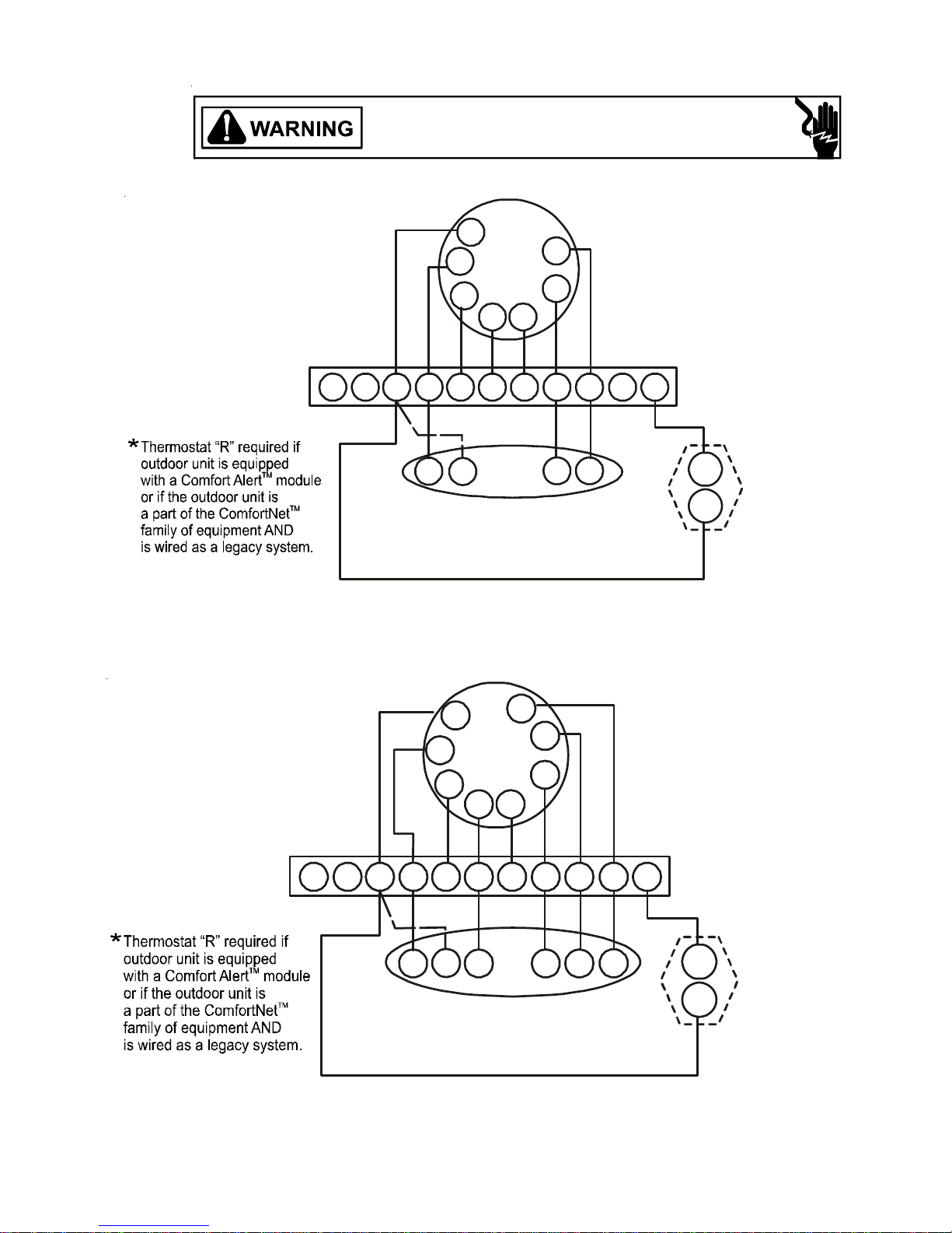
This modular blower is a part of the ComfortNet™ family of
products. It may be installed as part of a “legacy” system
using a standard 24 VAC thermostat. However, with the
CTK01AAComfortNet™thermostatkit, this modular blower
may be installed as part of a digitally communicating sys-
tem. The ComfortNet™ system provides automatic airflow
configuration,enhanced setup features, and enhanceddiag-
nostics. Italso reduces the number of thermostat wiresto a
maximumoffour.
C
OMFORT
N
ET
™S
YSTEM
OVERVIEW
TheComfortNet™system(orCT™system)isasystemthat
includesaComfortNet™compatiblemodular blower and air
conditioner or heat pump with a CTK01AA thermostat. Any
other system configurations are considered invalid
ComfortNet™ systems and must be connected as a tradi-
tional (or legacy) system. The table below compares the
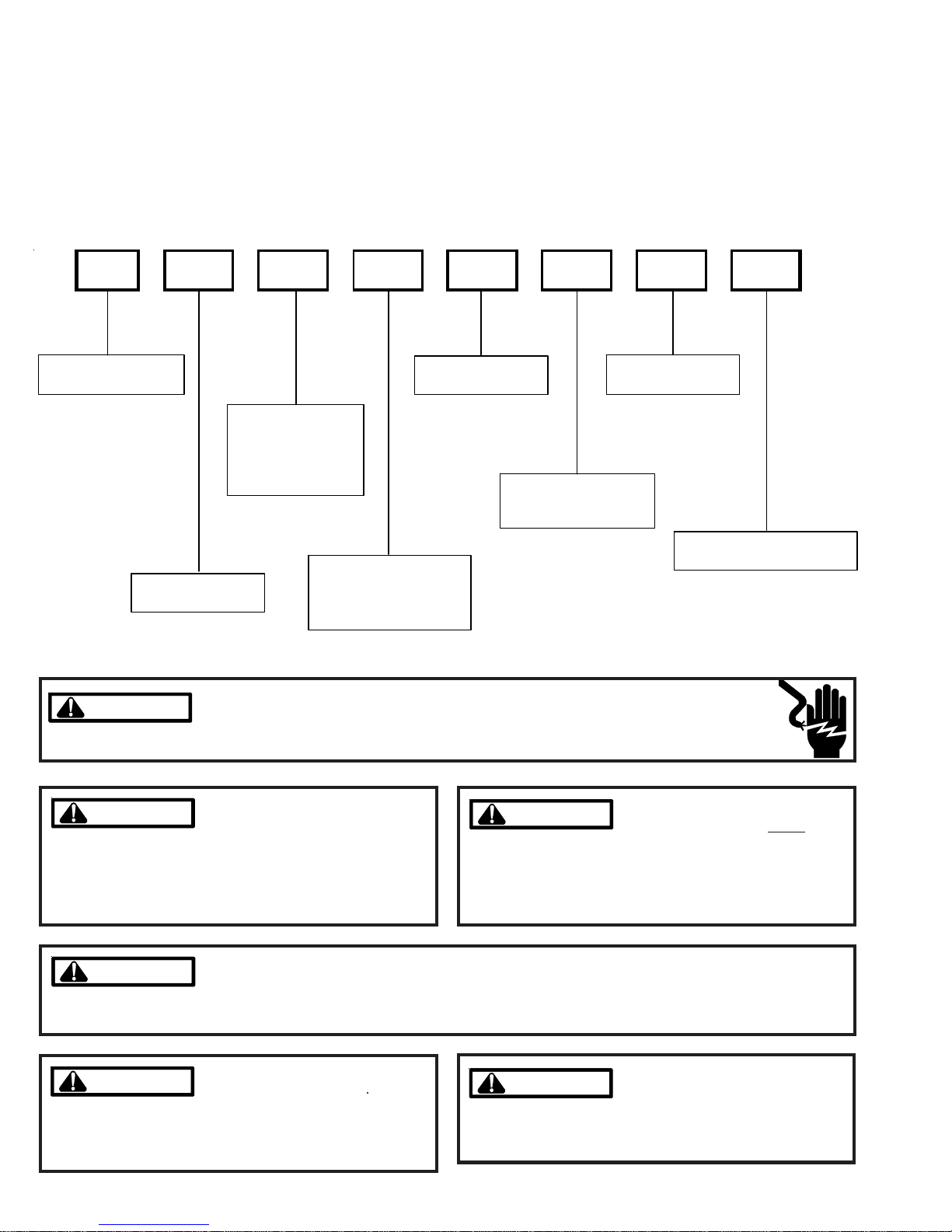
validCT™systems.
CT™ compatible
Modular Blower CT™ compatible
Air Conditioner Full CT™ system
benefits & features
CT™ compatible
Modular Blower CT™ compatible
Heat Pump Full CT™ system
benefits & features
AComfortNet™heating/airconditioning system differs from
alegacy/traditionalsystemin the manner in which the indoor
unit, outdoor unit and thermostat interact with one another.
In a traditional system, the thermostat sends commands to
theindoorandoutdoor units via analog 24 VACsignals. Itis
a one-way communication path in that the indoor and out-
door units typically do not return information to the thermo-
stat.
Ontheotherhand,theindoorunit, outdoor unit, and thermo-
statcomprisingaComfortNet™system“communicate”digi-
tally with one another. It is now a two-way communications
path. The thermostat still sends commands to the indoor
and outdoor units. However, the thermostat may also re-
questand receive informationfrom both theindoor and out-
door units. This information may be displayed on the CT™
thermostat. The indoor and outdoor units also interact with
one another. The outdoor unit may send commands to or
requestinformation from theindoorunit. Thistwo-waydigital
communications between the thermostat and subsystems
(indoor/outdoor unit) and between subsystems is the key to
unlockingthe benefits and features of the ComfortNet™ sys-
tem.
Two-waydigital communications is accomplished using only
twowires. Thethermostatandsubsystemcontrolsarepow-
eredwith 24 VAC Thus, amaximum of 4 wiresbetween the
equipment and thermostat is all that is required to operate
the system.

MBVC BLOWER SPECIFICATIONS
4
W
H
(3) KNOCKOUTS
1.125
1.375
1.750
.875 KNOCKOUT
(2 PLACES)
C
6 1/2
5
5 1/8 3 1/4
D
MBVC1200/1600/2000
Physical Information Shipping
Blower Wheel
(D x W) Blower Motor
(HP) MCA1MOP1WHD
Weight
lbs.(kg)
MBVC1200 10X8 1/2 4.3 15 17½
(445) 26
(660) 21
(533) 72
(32.6)
MBVC1600 10X8 3/4 6.3 15 21
(533) 30
(762) 21
(533) 82
(37.2)
MBVC2000 11X10 3/4 5.8 15 24½
(622) 30
(762) 21
(533) 94
(42.6)
1
MODEL Dimensions, inches (mm)
Minimum Circuit Ampacity (MCA) and Maximum Overcurrent Protection (MOP) for blower without supplemental heat
installed. Refer to unit nameplate for MCA and MOP with approved accessory heaters installed.

MBVC BLOWER SPECIFICATIONS
5
BLOWER OPENING DIMENSIONS
(TOP VIEW)
MBVC1200/1600/2000
HKR HEATER DATA
NO HEAT KIT HKR-03* HKR05-(C)* HKR-06* HKR-08(C)*
MBVC
1200AA-1AA X X X X X
1600AA-1AA X X X X X
2000AA-1AA X X X X X
^ = Circuit 1: Single Phase for Air Handler Motor * = Revision level that my or may not be designated
Circuit 2: 3-Phase for HKR3 Heater Kits C = Circuit Breaker option
X = Allowable combinations
~ = Restricted combinations
BLOWER HEATER KIT
HKR-10(C)* HKR-15C* HKR-20C* HKR-21C*
MBVC
1200AA-1AA X X ~ ~
1600AA-1AA X X ~ ~
2000AA-1AA X X X ~
^ = Circuit 1: Single Phase for Air Handler Motor * = Revision level that my or may not be desi
g
Circuit 2: 3-Phase for HKR3 Heater Kits C = Circuit Breaker option
X = Allowable combinations
~ = Restricted combinations
BLOWER HEATER KIT
S
M
A
L
L
M
E
D
I
U
M
L
A
R
G
E
13-1/4”
23-1/2”
11-5/16”
11”
20-1/16”
11-5/16”
10-7/8”
16-1/2”
10-1/4”

BLOWER PERFORMANCE DATA
6
3
4
Normal* +10%
Air flow Adjust Taps (*indicates factory setting)
-10% Normal
OFF OFF OFF OFFON ON ON ON
3
4
3
4
3
4
Thermostat "Fan Only" Mode
During "Fan Only" operations, the CFM output is 30% of the maximum CFM capability.
CFMTrimAdjust
Minoradjustments can be madethrough the dipswitchcombination of 3-4.
LocatetheblowerspeedselectionDIPswitchesontheintegrated control module. Select the desired
“cooling”speed tap by positioningswitches 1 and 2appropriately. Select the desired“adjust” tap by
positioningswitches3 and 4 appropriately. Refer to thefollowingfigure for switch positions andtheir
corresponding taps. Verify CFM by counting the number of times the green CFM LED blinks.
1234 5 6
400 600 OFF OFF OFF OFF OFF OFF
540 800 ON OFF ON OFF ON OFF
670 1000 OFF ON OFF ON OFF ON
800 1200 ON ON ON ON ON ON
670 1000 OFF OFF OFF OFF OFF OFF
800 1200 ON OFF ON OFF ON OFF
940 1400 OFF ON OFF ON OFF ON
1070 1600 ON ON ON ON ON ON
800 1200 OFF OFF OFF OFF OFF OFF
1070 1600 ON OFF ON OFF ON OFF
1200 1800 OFF ON OFF ON OFF ON
1340 2000 ON ON ON ON ON ON
ADJUST SELECTION
SWITCHES PROFILE SELECTION
SWITCHES
MBVC1200
MBVC1600
MBVC2000
COOL SELECTION
SWITCHESMODEL LOW STAGE
COOL HIGH STAGE
COOL
HTR kW MBVC1200* MBVC1600* MBVC2000* SWITCH
9SWITCH
10 SWITCH
11
3600800800ONONON
5600800800
ON ON OFF
6635800800
ON OFF ON
8 740 1000 1000 ON OFF OFF
10 1000 1000 1200 OFF ON ON
15 1400 1500 1500 OFF ON OFF
20 NR NR 2000 OFF OFF ON
21 NR NR NR ON^ ON^ ON^
^ Factory setting

WIRING DIAGRAMS
7
HIGH VOLTAGE!
DISCONNECT ALL POWER BEFORE SERVICING OR INSTALLING THIS
UNIT. MULTIPLE POWER SOURCES MAY BE PRESENT. FAILURE TO
DO SO MAY CAUSE PROPERTY DAMAGE, PERSONAL INJURY OR DEATH.
Wiring is subject to change. Always refer to the wiring diagram on the unit for the most up-to-date wiring.
TypicalTwo-StageCoolingwithTwo-StageHeating
TypicalTwoStageHeat Pump heating andAuxiliary/EmergencyHeating
THERMOSTATS
Y1
12RC
C
Modular Blower
Integrated Control Module
Typical Two-Stage Cool, Two-Stage Heat
Thermostat
Dehumidistat
[Optional]
G
W1 W2 Y1 Y2
O
Y2
W1 W2
Y1 Y2
Remote Condensing Unit
(Two-Stage AC)
NEU
HOT
DEHUM
CR
G
R
*
Y1
12RC
C
Modular Blower
Integrated Control Module
Typical Two-Stage Cool,
Two-Stage Heat
Heat Pump Thermostat
Dehumidistat
[Optional]
G
W1 W2 Y1 Y2
O
DEHUM
RY2
W2
Y1 Y2
Remote Condensing Unit
(Two-Stage HP)
NEU
HOT
O
EMR
W1
O
C
G
R
*

WIRING DIAGRAMS
8
HIGH VOLTAGE!
DISCONNECT ALL POWER BEFORE SERVICING OR INSTALLING THIS
UNIT. MULTIPLE POWER SOURCES MAY BE PRESENT. FAILURE TO
DO SO MAY CAUSE PROPERTY DAMAGE, PERSONAL INJURY OR DEATH.
Wiring is subject to change. Always refer to the wiring diagram on the unit for the most up-to-date wiring.
2
7
GN
COOL
DELAY
RD
TERM
3
BL
R
D
8
GN
RD
B
K
ELEC
RD
9
2
3
BK BL
SEE NOTE 6
1
BK
BIAS
UNUSED
BR
6
6
PL2
BL
5
BK
4
BIAS
7
9
8
3
ADJUST
5
LEARN
-
4
RD
DEHUM
SEE
NOTE
7
24
PL1
WH RD
SEE
NOTE 5
11
HEAT
AF
YL BK
BK
HTR1
8
L2
FL FL
RD
BK
WH
2
M7
YL
FL
RD
6
R
BL
HTR2
NOTE: WHEN INSTALLING HEATER KIT, ENSURE SPEED TAP DOES NOT EXCEED MINIMUM BLOWER SPEED (MBS) SPECIFIED FOR THE AIRHANDLER/HEATER
TL TL
TWO (2) ELEMENT ROWS
8
L1
BK
M4
M2
HTR2
R2
9
L2
RD
M1
3
BK
1
BK
M1
BK
BL
ONE (1) ELEMENT ROWS
TL
HTR3
TL
M2
M3
YL
HTR2
RD
FL
BL
L1
TL
L1
4
R2
HTR3
9
RD
8
RD
M4
R1
BK
M3
9
WH
BK
BL
M3
6
BK
RD
BK
PU
RD
6
4
BK
KIT COMBINATION ON THIS UNIT'S S&R PLATE. AFTER INSTALLING OPTIONAL HEAT KIT, MARK AN "X" IN THE PROVIDED ABOVE.
FL
M2
PU
R1
HTR4
TL
HTR1
FL
BK
M6
PU
HTR1
M1
2
WH
M1
5
PLM
BK
TL
BR
RD
BK
MARK ACCORDING TO NUMBER OF HEATER ELEMENT ROWS INSTALLED. NO MARK INDICATES NO HEAT KIT INSTALLED.
6
WH
7
M1
BK
9
TL
FL
YL
BR
1
PU
YL
BK
BL
BK
PLM
7
5
RD 7
M8
RD
2
BL
BL
L2
TL
THREE (3) ELEMENT ROWS
RD
7
3
1
FL
L2
BL
RD
4
L1
L1
L2
R
M2
PLM
2
M5
5
1
4
HTR1
M2
FOUR (4) ELEMENT ROWS
TL
FL
BK
5
RD
RD
L1
PLM
3
RD
BK
8
YL
RD
L2
BK
BK
3
RD
BL
FL
M4
RD
0140A00039 REV. A
BLWR
OVERCURRENT
TR
HEAT SEQUENCER R1
24 V THERMOSTAT CONNECTIONS
GN GREEN
TRANSFORMER
HEAT SEQUENCER R2
GND
FIELD GND
INTERNALTO
TWO-STAGE INTEGRATED CONTROL MODULE TX (3)
DEHUM
C
W1 (1)
5
FIELD SPLICE
W1
CFM LED
R
Y1
NOTES:
LOW VOLTAGE (24V)
4
GND
W1
24 V
3A
4
RX (2)
COLOR CODES:
Y2
TH
STATUS
LED
5. TO RECALL THE LAST 6 FAULTS, MOST RECENT TO LEAST RECENT,
DEPRESS SWITCH FOR MORETHAN 2 SECONDSWHILE IN STANDBY(N
THERMOSTAT INPUTS).
208 VAC
Y1
+VDC (1)
TH
INTEGRATED CONTROL
INDOOR
PROT. DEVICE
2GND (4)
1
CTR
RESISTER
Y2
2
BR BROWN
DISCONNECT
L2
W2
YL YELLOW
1. PLACE RED WIRE ON TRANSFORMER TERMINAL 2 FOR 208 VAC
OPERATION.
7. DISCARD CONNECTOR PL1 WHEN INSTALLING OPTIONAL HEAT KIT.
COM
24V THERMOSTAT CONNECTIONS
4
RX LED
3. IF ANY OF THE ORIGINAL WIRE AS SUPPLIED WITH THE BLOWER MUST
BE REPLACED, IT MUST BE REPLACED WITH WIRING MATERIAL HAVING A
TEMPERATURE RATING OF AT LEAST 105°C. USE COPPER CONDUCTORS
ONLY.
HI VOLTAGE (230V)
3
6. BIASAND TERM DIPSWITCHES MUST BEIN "ON" POSITION. RED
STATUS LED PROVIDES NETWORK STATUS. GREEN RX LED INDICATES
NETWORK TRAFFIC. USE LEARN BUTTON TO RESET NETWORK.
W2
2
1
O
INTEGRATED CONTROL MODULE
G
VT VIOLET
G
COM
L1
L2
GND
ECM MOTOR
HARNESS
JUNCTION
GND
208/230 VAC
FUSE 3 A
WH WHITE
1
4. UNIT MUST BE PERMANENTLY GROUNDEDAND CONFORM TO N.E.C.AND
LOCAL CODES.
24 VAC
INDOOR
L1
40 VATRANSFORMER, SEE NOTE 1
HI VOLTAGE FIELD
3
1
LOW VOLTAGE FIELD
3
2
40 VA
AIR
DIP SWITCHES
BLWR
FUSE
24 VAC
RD RED
DEHUM
PLUG CONNECTION
O
GY GRAY
TERMINAL
EQUIPMENT GND
PK PINK
BL BLUE
DIAGNOSTIC
LED
230 VAC
AIR
W2 (2)
RTO
MICRO
CIRCULATOR
CIRCULATOR
OR ORANGE
BK BLACK
2. MANUFACTURER'S SPECIFIED REPLACEMENT PARTS MUST BE USED
WHEN SERVICING.
CIRCULATOR BLOWER
COM
4 CIRCUIT HEATER
CONNECTOR
BL
GY
BKRD
GND
This manual suits for next models
3
Table of contents
Other Goodman Blower manuals