6
2. Firmly touch a clean, unpainted, metal surface of the furnace
near the control. Any tools held in a person’s hand during
grounding will be discharged.
3. Service integrated control module or connecting wiring
following the discharge process in step 2. Use caution not to
recharge your body with static electricity; (i.e., do not move
or shuffle your feet, do not touch ungrounded objects, etc.).
If you come in contact with an ungrounded object, repeat
step 2 before touching control or wires.
4. Dischargeyourbodytogroundbefore removing anewcontrol
from its container. Follow steps 1 through 3 if installing the
control on a furnace. Return any old or new controls to their
containers before touching any ungrounded object.
III. PRIII. PR
III. PRIII. PR
III. PROO
OO
ODUCDUC
DUCDUC
DUCT APPLIT APPLI
T APPLIT APPLI
T APPLICC
CC
CAA
AA
ATITI
TITI
TIOO
OO
ONN
NN
N
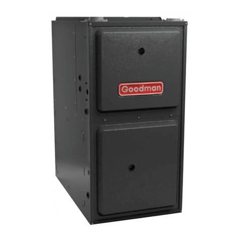
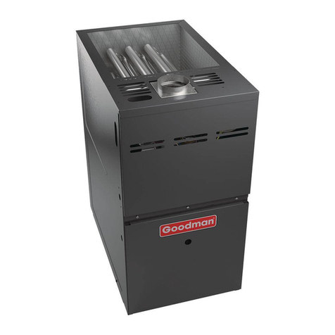
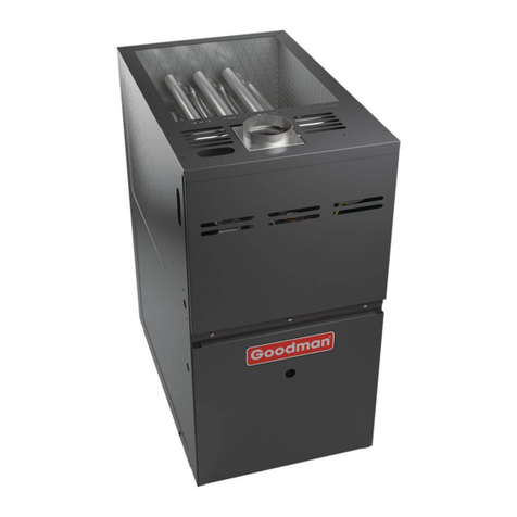
This furnace is primarily designed for residential home-heating ap-
plications. It is NOT designed or certified for use in mobile homes,
trailers or recreational vehicles. This unit is NOT designed or certi-
fied for outdoor applications. The furnace must be installed indoors
(i.e., attic space, crawl space, or garage area provided the garage
area is enclosed with an operating door).
This furnace can be used in the following non-industrial commercial
applications:
Schools, Office buildings, Churches, Retail stores
Nursing homes, Hotels/motels, Common or office areas
In such applications , the furnace must be installed with the follow-
ing stipulations:
• Itmustbeinstalledpertheinstallation instructions provided
and per local and national codes.
• It must be installed indoors in a building constructed on
site.
• It must be part of a ducted system and not used in a free
air delivery application.
• It must not be used as a “make-up” air unit.
• It must be installed with two-pipe systems for combustion
air, especially if VOC’s or other contaminants are present
in the conditioned space.
• All other warranty exclusions and restrictions apply This
furnace is an ETL dual-certified appliance and is
appropriate for use with natural or propane gas (NOTE: If
using propane, a propane conversion kit is required).
Dual certification means that the combustion air inlet pipe is op-
tional and the furnace can be vented as a:
Non-direct vent (single pipe) central forced air furnace in
which combustion air is taken from the installation area or
from air ducted from the outside or,
Direct vent (dual pipe) central forced air furnace in which
all combustion air supplied directly to the furnace burners
through a special air intake system outlined in these
instructions.
To ensure proper installation and operation, thoroughly read this
manual for specifics pertaining to the installation and application of
this product.
WARNING
POSSIBLE PROPERTY DAMAGE, PERSONAL INJURY OR DEATH DUE TO FIRE,
EXPLOSION, SMOKE, SOOT, CONDENSTAION, ELECTRICAL SHOCK OR CARBON
MONOXIDE MAY RESULT FROM IMPROPER INSTALLATION, REPAIR, OPERATION,
OR MAINTENANCE OF THIS PRODUCT.
II. SAFETII. SAFET
II. SAFETII. SAFET
II. SAFETYY
YY
Y
Please adhere to the following warnings and cautions when install-
ing, adjusting, altering, servicing, or operating the furnace.
TO PREVENT PERSONAL INJURY OR DEATH DUE TO IMPROPER INSTALLATION,
ADJUSTMENT, ALTERATION, SERVICE OR MAINTENANCE, REFER TO THIS
MANUAL. FOR ADDITIONAL ASSISTANCE OR INFORMATION, CONSULT A
QUALIFIED INSTALLER, SERVICE AGENCY OR THE GAS SUPPLIER.
WARNING
WARNING
THIS PRODUCT CONTAINS OR PRODUCES A CHEMICAL OR CHEMICALS WHICH
MAY CAUSE SERIOUS ILLNESS OR DEATH AND WHICH ARE KNOWN TO THE
STATE OF CALIFORNIA TO CAUSE CANCER, BIRTH DEFECTS OR OTHER
REPRODUCTIVE HARM.
WARNING
TO PREVENT POSSIBLE PROPERTY DAMAGE, PERSONAL INJURY OR DEATH
DUE TO ELECTRICAL SHOCK, THE FURNACE MUST BE LOCATED TO PROTECT
THE ELECTRICAL COMPONENTS FROM WATER.
WARNING
THIS UNIT MUST NOT BE USED AS A "CONSTRUCTION HEATER" DURING THE
FINISHING PHASES OF CONSTRUCTION ON A NEW STRUCTURE. THIS TYPE OF
USE MAY RESULT IN PREMATURE FAILURE OF THE UNIT DUE TO EXTREMELY
LOW RETURN AIR TERMPERATURES AND EXPOSURE TO CORROSIVE OR VERY
DIRTY ATMOSPHERES.
WARNING
HEATING UNIT SHOULD NOT BE UTILIZED WITHOUT REASONABLE, ROUTINE,
INSPECTION, MAINTENANCE AND SUPERVISION. IF THE BUILIDNG IN WHICH ANY
SUCH DEVICE IS LOCATED WILL BE VACANT, CARE SHOULD BE TAKEN THAT
SUCH DEVICE IS ROUTINELY INSPECTED, MAINTAINED AND MONITORED. IN THE
EVENT THAT THE BUILDING MAYBE EXPOSED TO FREEZING TEMPERATURES
AND WILL BE VACANT, ALL WATER-BEARING PIPES SHOULD BE DRAINED, THE
BUILDING SHOULD BE PROPERLY WINTERIZED, AND THE WATER SOURCE
CLOSED. IN THE EVENT THAT THE BUILDING MAY BE EXPOSED TO FREEZING
TEMPERATURES AND WILL BE VACANT, ANY HYDRONIC COIL UNITS SHOULD
BE DRAINED AS WELL AND, IN SUCH CASE, ALTERNATIVE HEAT SOURCES
SHOULD BE UTILIZED.
ELECTROSTATIC DISCHARGE (ESD) PRECAUTIONS
NOTE: Discharge static electricity accumulated in the body before
touching the unit. An electrostatic discharge can adversely affect
electrical components.
Use the following precautions during furnace installation and ser-
vicing to protect the integrated control module from damage. By
putting the furnace, the control, and the person at the same electro-
static potential, these steps will help avoid exposing the integrated
control module to electrostatic discharge. This procedure is appli-
cable to both installed and non-installed (ungrounded) furnaces.
1. Disconnect all power to the furnace. Do not touch the
integratedcontrolmoduleoranywire connected to thecontrol
prior to discharging your body’s electrostatic charge to
ground.
